Page 1686 of 2493
Service Data and Specifications (SDS)
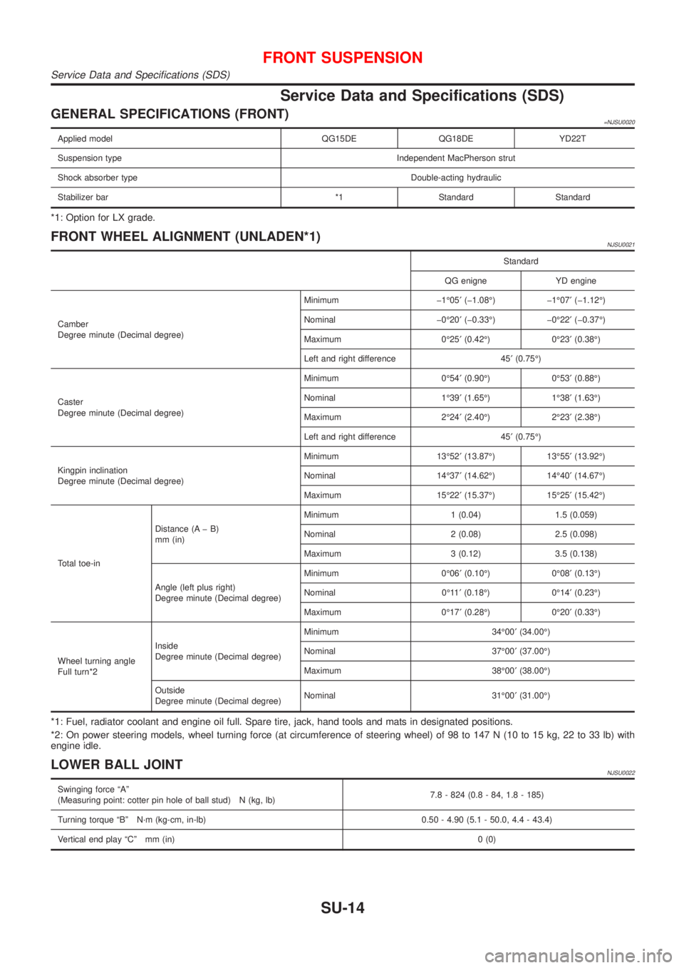
GENERAL SPECIFICATIONS (FRONT)=NJSU0020
Applied model QG15DE QG18DE YD22T
Suspension type Independent MacPherson strut
Shock absorber type Double-acting hydraulic
Stabilizer bar *1 Standard Standard
*1: Option for LX grade.
FRONT WHEEL ALIGNMENT (UNLADEN*1)NJSU0021
Standard
QG enigne YD engine
Camber
Degree minute (Decimal degree)Minimum þ1É05¢(þ1.08É) þ1É07¢(þ1.12É)
Nominal þ0É20¢(þ0.33É) þ0É22¢(þ0.37É)
Maximum 0É25¢(0.42É) 0É23¢(0.38É)
Left and right difference 45¢(0.75É)
Caster
Degree minute (Decimal degree)Minimum 0É54¢(0.90É) 0É53¢(0.88É)
Nominal 1É39¢(1.65É) 1É38¢(1.63É)
Maximum 2É24¢(2.40É) 2É23¢(2.38É)
Left and right difference 45¢(0.75É)
Kingpin inclination
Degree minute (Decimal degree)Minimum 13É52¢(13.87É) 13É55¢(13.92É)
Nominal 14É37¢(14.62É) 14É40¢(14.67É)
Maximum 15É22¢(15.37É) 15É25¢(15.42É)
Total toe-inDistance (A þ B)
mm (in)Minimum 1 (0.04) 1.5 (0.059)
Nominal 2 (0.08) 2.5 (0.098)
Maximum 3 (0.12) 3.5 (0.138)
Angle (left plus right)
Degree minute (Decimal degree)Minimum 0É06¢(0.10É) 0É08¢(0.13É)
Nominal 0É11¢(0.18É) 0É14¢(0.23É)
Maximum 0É17¢(0.28É) 0É20¢(0.33É)
Wheel turning angle
Full turn*2Inside
Degree minute (Decimal degree)Minimum 34É00¢(34.00É)
Nominal 37É00¢(37.00É)
Maximum 38É00¢(38.00É)
Outside
Degree minute (Decimal degree)Nominal 31É00¢(31.00É)
*1: Fuel, radiator coolant and engine oil full. Spare tire, jack, hand tools and mats in designated positions.
*2: On power steering models, wheel turning force (at circumference of steering wheel) of 98 to 147 N (10 to 15 kg, 22 to 33 lb) with
engine idle.
LOWER BALL JOINTNJSU0022
Swinging force ªAº
(Measuring point: cotter pin hole of ball stud) N (kg, lb)7.8 - 824 (0.8 - 84, 1.8 - 185)
Turning torque ªBº N´m (kg-cm, in-lb) 0.50 - 4.90 (5.1 - 50.0, 4.4 - 43.4)
Vertical end play ªCº mm (in)0 (0)
FRONT SUSPENSION
Service Data and Specifications (SDS)
SU-14
Page 1687 of 2493
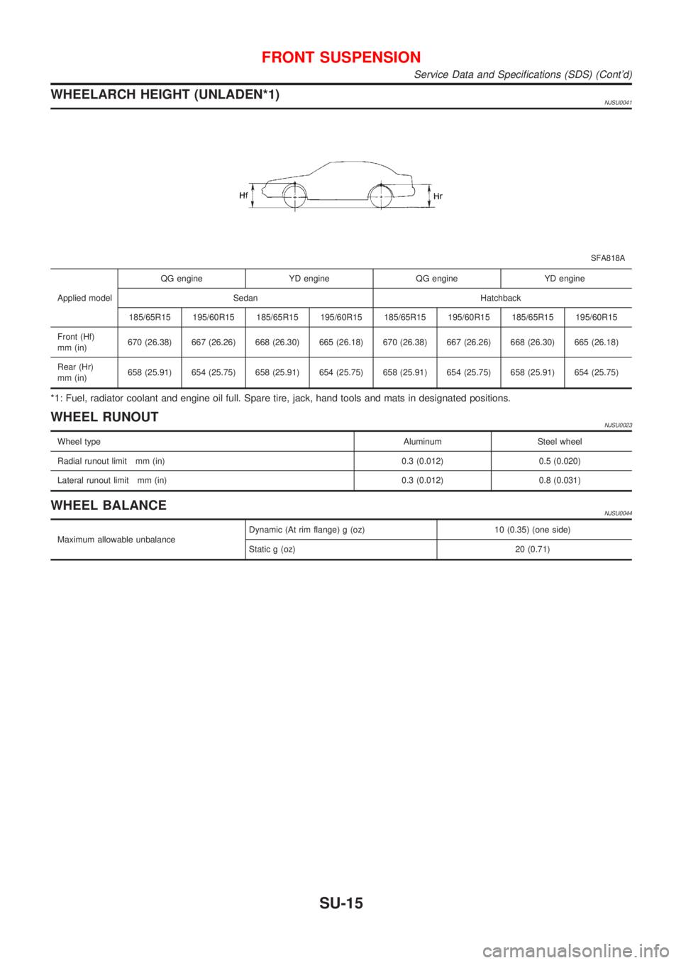
WHEELARCH HEIGHT (UNLADEN*1)NJSU0041
SFA818A
Applied modelQG engine YD engine QG engine YD engine
Sedan Hatchback
185/65R15 195/60R15 185/65R15 195/60R15 185/65R15 195/60R15 185/65R15 195/60R15
Front (Hf)
mm (in)670 (26.38) 667 (26.26) 668 (26.30) 665 (26.18) 670 (26.38) 667 (26.26) 668 (26.30) 665 (26.18)
Rear (Hr)
mm (in)658 (25.91) 654 (25.75) 658 (25.91) 654 (25.75) 658 (25.91) 654 (25.75) 658 (25.91) 654 (25.75)
*1: Fuel, radiator coolant and engine oil full. Spare tire, jack, hand tools and mats in designated positions.
WHEEL RUNOUTNJSU0023
Wheel typeAluminum Steel wheel
Radial runout limit mm (in) 0.3 (0.012) 0.5 (0.020)
Lateral runout limit mm (in) 0.3 (0.012) 0.8 (0.031)
WHEEL BALANCENJSU0044
Maximum allowable unbalanceDynamic (At rim flange) g (oz) 10 (0.35) (one side)
Static g (oz) 20 (0.71)
FRONT SUSPENSION
Service Data and Specifications (SDS) (Cont'd)
SU-15
Page 1697 of 2493
Service Data and Specifications (SDS)
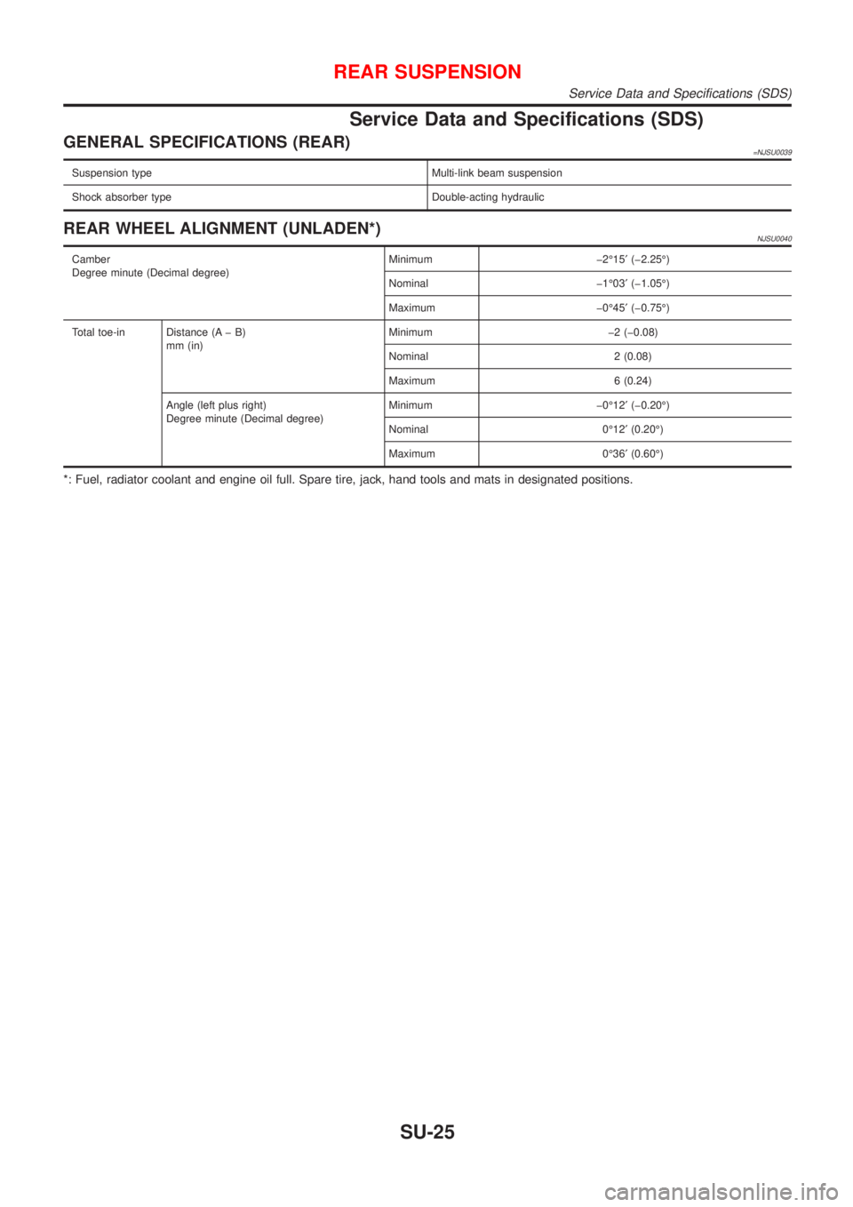
GENERAL SPECIFICATIONS (REAR)=NJSU0039
Suspension type Multi-link beam suspension
Shock absorber type Double-acting hydraulic
REAR WHEEL ALIGNMENT (UNLADEN*)NJSU0040
Camber
Degree minute (Decimal degree)Minimum þ2É15¢(þ2.25É)
Nominal þ1É03¢(þ1.05É)
Maximum þ0É45¢(þ0.75É)
Total toe-in Distance (A þ B)
mm (in)Minimum þ2 (þ0.08)
Nominal 2 (0.08)
Maximum 6 (0.24)
Angle (left plus right)
Degree minute (Decimal degree)Minimum þ0É12¢(þ0.20É)
Nominal 0É12¢(0.20É)
Maximum 0É36¢(0.60É)
*: Fuel, radiator coolant and engine oil full. Spare tire, jack, hand tools and mats in designated positions.
REAR SUSPENSION
Service Data and Specifications (SDS)
SU-25
Page 1701 of 2493
Supplemental Restraint System (SRS) ªAIR
BAGº and ªSEAT BELT PRE-TENSIONERº
NJBR0139The Supplemental Restraint System such as ªAIR BAGº and ªSEAT BELT PRE-TENSIONERº used along with
a seat belt, helps to reduce the risk or severity of injury to the driver and front passenger for certain types of
collision. The SRS system composition which is available to NISSAN MODEL N16 is as follows (The compo-
sition varies according to the destination and optional equipment.):
+For a frontal collision
The Supplemental Restraint System consists of driver air bag module (located in the center of the steer-
ing wheel), front passenger air bag module (located on the instrument panel on passenger side), front seat
belt pre-tensioners, a diagnosis sensor unit, warning lamp, wiring harness and spiral cable.
+For a side collision
The Supplemental Restraint System consists of front side air bag module (located in the outer side of front
seat), side air bag (satellite) sensor, diagnosis sensor unit (one of components of air bags for a frontal
collision), wiring harness, warning lamp (one of components of air bags for a frontal collision).
Information necessary to service the system safely is included in theRS sectionof this Service Manual.
WARNING:
+To avoid rendering the SRS inoperative, which could increase the risk of personal injury or death
in the event of a collision which would result in air bag inflation, all maintenance should be per-
formed by an authorized NISSAN dealer.
+Improper maintenance, including incorrect removal and installation of the SRS, can lead to per-
sonal injury caused by unintentional activation of the system. For removal of Spiral Cable and Air
Bag Module, see the RS section.
+Do not use electrical test equipment on any circuit related to the SRS unless instructed to in this
Service Manual. SRS wiring harnesses can be identified by yellow harness connector.
SBR686C
Precautions for Brake SystemNJBR0002+Recommended fluid is brake fluid ªDOT 4º.
+Never reuse drained brake fluid.
+Be careful not to splash brake fluid on painted areas.
+To clean or wash all parts of master cylinder, disc brake
caliper and wheel cylinder, use clean brake fluid.
+Never use mineral oils such as gasoline or kerosene. They
will ruin rubber parts of the hydraulic system.
+Use flare nut wrench when removing and installing brake
tube.
+Always torque brake lines when installing.
+Burnish the brake contact surfaces after refinishing or
replacing drums or rotors, after replacing pads or linings,
or if a soft pedal occurs at very low mileage.
Refer to ªBrake Burnishing Procedureº, ªON-VEHICLE
SERVICEº, BR-7.
WARNING:
+Clean brake pads and shoes with a waste cloth, then wipe
with a dust collector.
PRECAUTIONS
Supplemental Restraint System (SRS) ªAIR BAGº and ªSEAT BELT PRE-TENSIONERº
BR-3
Page 1733 of 2493
ComponentNJBR0038
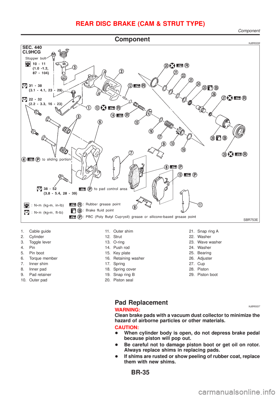
SBR753E
1. Cable guide
2. Cylinder
3. Toggle lever
4. Pin
5. Pin boot
6. Torque member
7. Inner shim
8. Inner pad
9. Pad retainer
10. Outer pad11. Outer shim
12. Strut
13. O-ring
14. Push rod
15. Key plate
16. Retaining washer
17. Spring
18. Spring cover
19. Snap ring B
20. Piston seal21. Snap ring A
22. Washer
23. Wave washer
24. Washer
25. Bearing
26. Adjuster
27. Cup
28. Piston
29. Piston boot
Pad ReplacementNJBR0037WARNING:
Clean brake pads with a vacuum dust collector to minimize the
hazard of airborne particles or other materials.
CAUTION:
+When cylinder body is open, do not depress brake pedal
because piston will pop out.
+Be careful not to damage piston boot or get oil on rotor.
Always replace shims in replacing pads.
+If shims are rusted or show peeling of rubber coat, replace
them with new shims.
REAR DISC BRAKE (CAM & STRUT TYPE)
Component
BR-35
Page 1736 of 2493
SBR088B
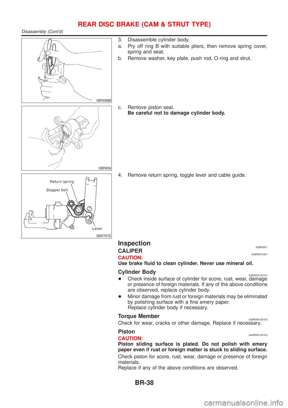
3. Disassemble cylinder body.
a. Pry off ring B with suitable pliers, then remove spring cover,
spring and seat.
b. Remove washer, key plate, push rod, O-ring and strut.
SBR656
c. Remove piston seal.
Be careful not to damage cylinder body.
SBR767E
4. Remove return spring, toggle lever and cable guide.
InspectionNJBR0041CALIPERNJBR0041S01CAUTION:
Use brake fluid to clean cylinder. Never use mineral oil.
Cylinder BodyNJBR0041S0101+Check inside surface of cylinder for score, rust, wear, damage
or presence of foreign materials. If any of the above conditions
are observed, replace cylinder body.
+Minor damage from rust or foreign materials may be eliminated
by polishing surface with a fine emery paper.
Replace cylinder body if necessary.
Torque MemberNJBR0041S0102Check for wear, cracks or other damage. Replace if necessary.
PistonNJBR0041S0103CAUTION:
Piston sliding surface is plated. Do not polish with emery
paper even if rust or foreign matter is stuck to sliding surface.
Check piston for score, rust, wear, damage or presence of foreign
materials.
Replace if any of the above conditions are observed.
REAR DISC BRAKE (CAM & STRUT TYPE)
Disassembly (Cont'd)
BR-38
Page 1741 of 2493
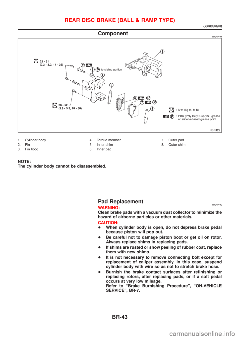
ComponentNJBR0141
NBR422
1. Cylinder body
2. Pin
3. Pin boot4. Torque member
5. Inner shim
6. Inner pad7. Outer pad
8. Outer shim
NOTE:
The cylinder body cannot be disassembled.
Pad ReplacementNJBR0142WARNING:
Clean brake pads with a vacuum dust collector to minimize the
hazard of airborne particles or other materials.
CAUTION:
+When cylinder body is open, do not depress brake pedal
because piston will pop out.
+Be careful not to damage piston boot or get oil on rotor.
Always replace shims in replacing pads.
+If shims are rusted or show peeling of rubber coat, replace
them with new shims.
+It is not necessary to remove connecting bolt except for
replacement of caliper assembly. In this case, suspend
cylinder body with wire so as not to stretch brake hose.
+Burnish the brake contact surfaces after refinishing or
replacing rotors, after replacing pads, or if a soft pedal
occurs at very low mileage.
Refer to ªBrake Burnishing Procedureº, ªON-VEHICLE
SERVICEº, BR-7.
REAR DISC BRAKE (BALL & RAMP TYPE)
Component
BR-43
Page 1820 of 2493
Steering Gear and LinkageNJST0035
Applied modelQG engine YD engine
Steering gear typePR25T
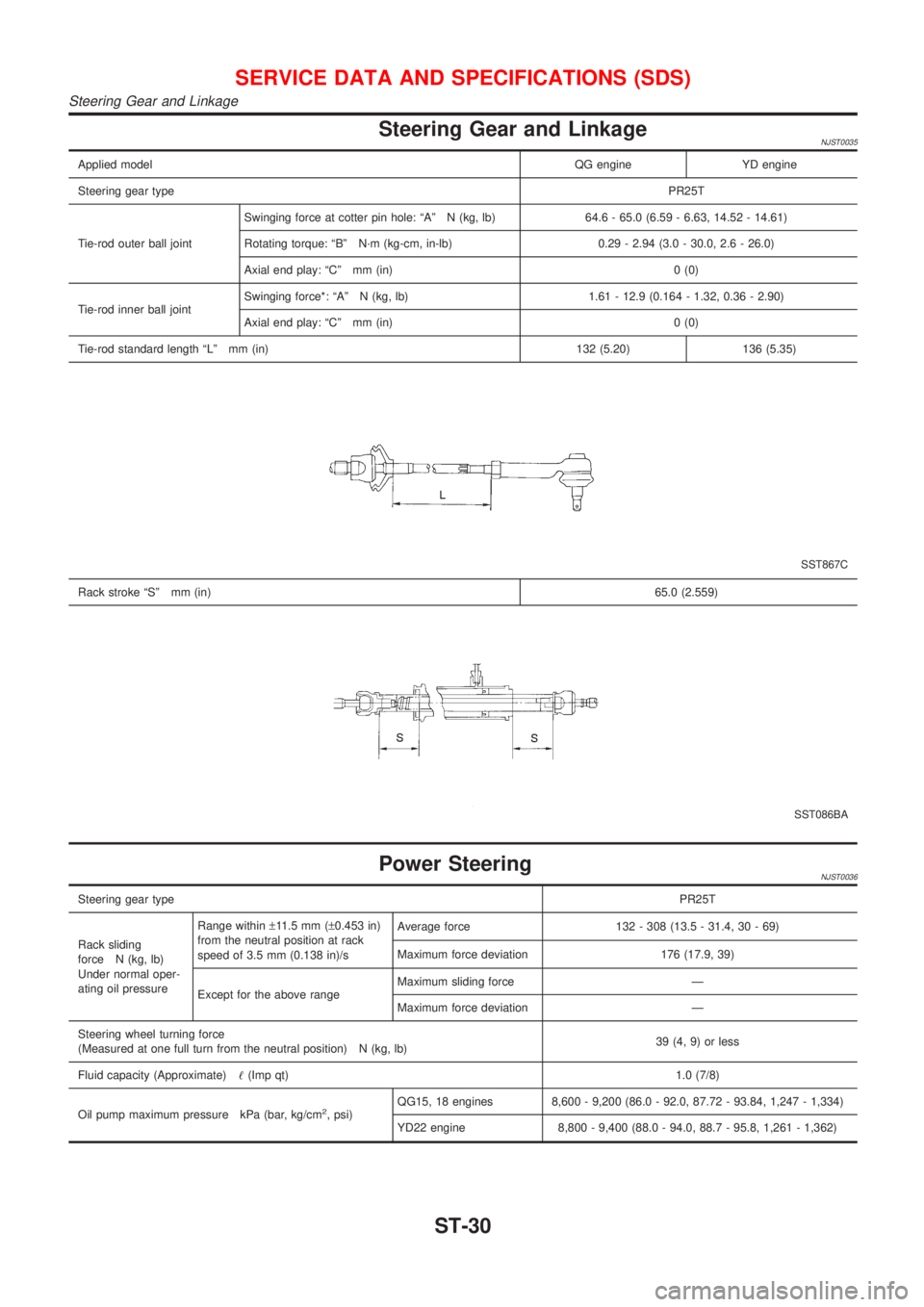
Tie-rod outer ball jointSwinging force at cotter pin hole: ªAº N (kg, lb) 64.6 - 65.0 (6.59 - 6.63, 14.52 - 14.61)
Rotating torque: ªBº N´m (kg-cm, in-lb) 0.29 - 2.94 (3.0 - 30.0, 2.6 - 26.0)
Axial end play: ªCº mm (in) 0 (0)
Tie-rod inner ball jointSwinging force*: ªAº N (kg, lb) 1.61 - 12.9 (0.164 - 1.32, 0.36 - 2.90)
Axial end play: ªCº mm (in) 0 (0)
Tie-rod standard length ªLº mm (in) 132 (5.20) 136 (5.35)
SST867C
Rack stroke ªSº mm (in)65.0 (2.559)
SST086BA
Power SteeringNJST0036
Steering gear typePR25T
Rack sliding
force N (kg, lb)
Under normal oper-
ating oil pressureRange within±11.5 mm (±0.453 in)
from the neutral position at rack
speed of 3.5 mm (0.138 in)/sAverage force 132 - 308 (13.5 - 31.4, 30 - 69)
Maximum force deviation 176 (17.9, 39)
Except for the above rangeMaximum sliding force Ð
Maximum force deviation Ð
Steering wheel turning force
(Measured at one full turn from the neutral position) N (kg, lb)39 (4, 9) or less
Fluid capacity (Approximate)!(Imp qt)1.0 (7/8)
Oil pump maximum pressure kPa (bar, kg/cm
2, psi)QG15, 18 engines 8,600 - 9,200 (86.0 - 92.0, 87.72 - 93.84, 1,247 - 1,334)
YD22 engine 8,800 - 9,400 (88.0 - 94.0, 88.7 - 95.8, 1,261 - 1,362)
SERVICE DATA AND SPECIFICATIONS (SDS)
Steering Gear and Linkage
ST-30