Page 114 of 2493

SEM878F
22. Remove cylinder head bolts.
23. Remove cylinder head with manifolds.
+Head warpage or cracking could result from removing in
incorrect order.
+Cylinder head bolts should be loosened in two or three
steps.
SEM914F
DisassemblyNJEM00181. Remove valve components with Tool.
2. Remove valve oil seal with a suitable tool.
SEM915F
InspectionNJEM0019CYLINDER HEAD DISTORTIONNJEM0019S01+Clean surface of cylinder head.
+Use a reliable straightedge and feeler gauge to check the flat-
ness of cylinder head mating surface.
+Check along six positions shown in figure.
Head surface flatness:
Standard: Less than 0.03 mm (0.0012 in)
Limit: 0.1 mm (0.004 in)
If beyond the specified limit, replace or resurface it.
Resurfacing limit:
The limit for cylinder head resurfacing is determined by the
amount of cylinder block resurfacing.
Amount of cylinder head resurfacing is ªAº.
Amount of cylinder block resurfacing is ªBº.
The maximum limit is as follows:
A + B = 0.2 mm (0.008 in)
After resurfacing cylinder head, check that camshaft rotates freely
by hand. If resistance is felt, replace cylinder head.
Nominal cylinder head height:
117.8 - 118.0 mm (4.638 - 4.646 in)
CAMSHAFT VISUAL CHECKNJEM0019S02Check camshaft for scratches, seizure and wear.
CYLINDER HEADQG
Removal (Cont'd)
EM-36
Page 123 of 2493
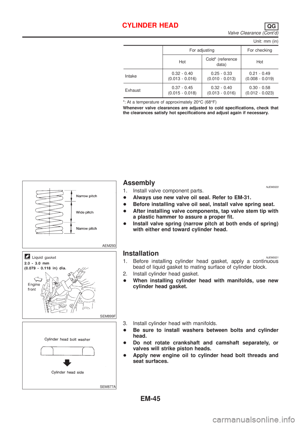
Unit: mm (in)
For adjusting For checking
HotCold* (reference
data)Hot
Intake0.32 - 0.40
(0.013 - 0.016)0.25 - 0.33
(0.010 - 0.013)0.21 - 0.49
(0.008 - 0.019)
Exhaust0.37 - 0.45
(0.015 - 0.018)0.32 - 0.40
(0.013 - 0.016)0.30 - 0.58
(0.012 - 0.023)
*: At a temperature of approximately 20ÉC (68ÉF)
Whenever valve clearances are adjusted to cold specifications, check that
the clearances satisfy hot specifications and adjust again if necessary.
AEM293
AssemblyNJEM00201. Install valve component parts.
+Always use new valve oil seal. Refer to EM-31.
+Before installing valve oil seal, install valve spring seat.
+After installing valve components, tap valve stem tip with
a plastic hammer to assure a proper fit.
+Install valve spring (narrow pitch at both ends of spring)
with either end toward cylinder head.
SEM899F
InstallationNJEM00211. Before installing cylinder head gasket, apply a continuous
bead of liquid gasket to mating surface of cylinder block.
2. Install cylinder head gasket.
+When installing cylinder head with manifolds, use new
cylinder head gasket.
SEM877A
3. Install cylinder head with manifolds.
+Be sure to install washers between bolts and cylinder
head.
+Do not rotate crankshaft and camshaft separately, or
valves will strike piston heads.
+Apply new engine oil to cylinder head bolt threads and
seat surfaces.
CYLINDER HEADQG
Valve Clearance (Cont'd)
EM-45
Page 124 of 2493

SEM900F
SEM614EC
SEM901F
+Tightening procedure
a. Tighten bolts to 29 N´m (3 kg-m, 22 ft-lb).
b. Tighten bolts to 59 N´m (6 kg-m, 43 ft-lb).
c. Loosen bolts completely.
d. Tighten bolts to 29 N´m (3 kg-m, 22 ft-lb).
e. Turn bolts 50 to 55 degrees clockwise or if angle wrench
is not available, tighten bolts to 59±4.9 N´m (6±0.5 kg-m,
43±3.6 ft-lb).
f. Tightening bolts (11 - 14) to 6.3 to 8.3 N´m (0.64 to 0.85
kg-m, 55.8 to 73.5 in-lb).
Tightening torque N´m (kg-m, ft-lb)
abcde,f
Bolts
(1-10)29
(3, 22)59
(6, 43)0
(0, 0)29
(3, 22)50-55
degrees or
59±4.9
(6±0.5,
43±3.6
ft-lb)
Bolts
(11-14)ÐÐÐÐ6.3 - 8.3
(0.64 -
0.85, 55.8 -
73.5 in-lb)
4. Install camshaft.
+The camshafts are distinguished by a paint mark as follows.
Intake camshaft: Other paint color than white
Exhaust camshaft: White paint or no paint
SEM902F
+Make sure camshafts are aligned as shown in figure.
SEM903F
5. Install camshaft brackets.
+Make sure camshaft brackets are aligned as marked dur-
ing disassembly.
CYLINDER HEADQG
Installation (Cont'd)
EM-46
Page 128 of 2493

WARNING:
+Position vehicle on a flat and solid surface.
+Place chocks at front and back of rear wheels.
+Do not remove engine until exhaust system has com-
pletely cooled off, otherwise, you may burn yourself
and/or fire may break out in fuel line.
+Before disconnecting fuel hose, release pressure.
Refer to EC-38, ªFuel Pressure Releaseº.
+Be sure to lift engine and transaxle in a safe manner.
+For engines not equipped with engine slingers, attach
proper slingers and bolts described in PARTS CATALOG.
CAUTION:
+When lifting engine, be sure to clear surrounding parts.
Use special care near accelerator wire casing, brake lines
and brake master cylinder.
+When lifting the engine, always use engine slingers in a
safe manner.
+When removing drive shaft, be careful not to damage
grease seal of transaxle.
+Before separating engine and transaxle, remove crank-
shaft position sensor (POS) from the cylinder block
assembly.
+Always be extra careful not to damage edge of crankshaft
position sensor (POS), or signal plate teeth.
Engine cannot be removed separately from transaxle. Remove
engine with transaxle as an assembly.
REMOVALNJEM0022S011. Drain coolant from radiator and cylinder block. Refer to LC-17,
ªChanging Engine Coolantº.
2. Remove coolant reservoir tank and bracket.
3. Drain engine oil.
4. Remove battery and battery tray.
5. Remove air cleaner and air duct.
6. Remove drive belts.
7. Remove alternator and air conditioner compressor from
engine.
8. Remove power steering oil pump from engine and position
aside.
Power steering oil pump does not need to be disconnected
from power steering tubes.
ENGINE ASSEMBLYQG
Removal and Installation (Cont'd)
EM-50
Page 130 of 2493
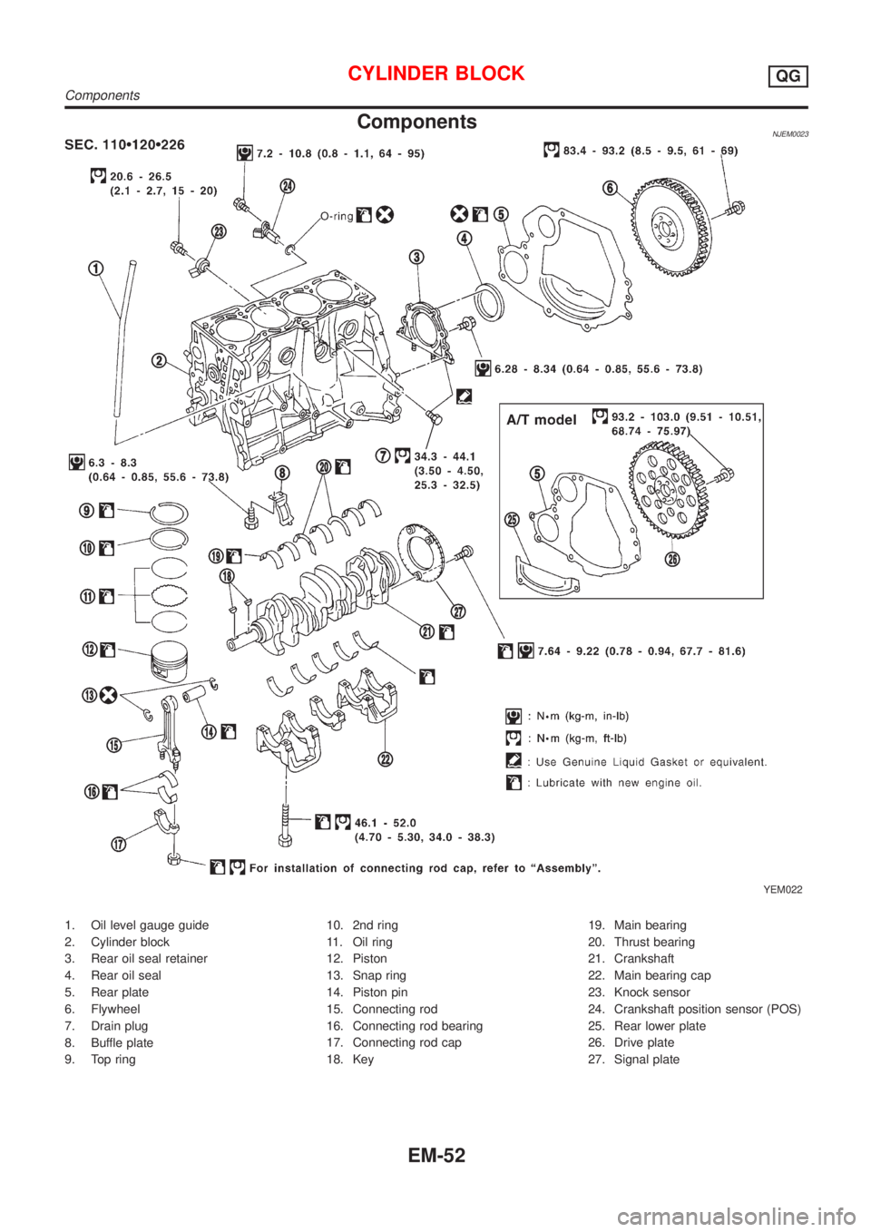
ComponentsNJEM0023
YEM022
1. Oil level gauge guide
2. Cylinder block
3. Rear oil seal retainer
4. Rear oil seal
5. Rear plate
6. Flywheel
7. Drain plug
8. Buffle plate
9. Top ring10. 2nd ring
11. Oil ring
12. Piston
13. Snap ring
14. Piston pin
15. Connecting rod
16. Connecting rod bearing
17. Connecting rod cap
18. Key19. Main bearing
20. Thrust bearing
21. Crankshaft
22. Main bearing cap
23. Knock sensor
24. Crankshaft position sensor (POS)
25. Rear lower plate
26. Drive plate
27. Signal plate
CYLINDER BLOCKQG
Components
EM-52
Page 131 of 2493

Removal and InstallationNJEM0024CAUTION:
+When installing sliding parts such as bearings and
pistons, apply engine oil on the sliding surfaces.
+Place removed parts, such as bearings and bearing caps,
in their proper order and direction.
+When installing connecting rod nuts and main bearing cap
bolts, apply new engine oil to threads and seating sur-
faces.
+Do not allow any magnetic materials to contact the signal
plate teeth of flywheel or drive plate, and rear plate.
+Remove the crankshaft position sensor (POS).
+Be careful not to damage sensor edges and single plate
teeth.
SEM927F
DisassemblyNJEM0025PISTON AND CRANKSHAFTNJEM0025S011. Place engine on a work stand.
2. Drain coolant and oil.
3. Remove timing chain.
Refer to EM-23.
SEM877B
4. Remove pistons with connecting rod.
+When disassembling piston and connecting rod, remove snap
ring first. Then heat piston to 60 to 70ÉC (140 to 158ÉF) or use
piston pin press stand at room temperature.
CAUTION:
+When piston rings are not replaced, make sure that piston
rings are mounted in their original positions.
+When replacing piston rings, if there is no punch mark,
install with either side up.
SEM165DB
5. Loosen main bearing caps in numerical order as shown in fig-
ure.
6. Remove bearing caps, main bearings and crankshaft.
+Before removing bearing caps, measure crankshaft end
play. Refer to EM-61.
+Bolts should be loosened in two or three steps.
CYLINDER BLOCKQG
Removal and Installation
EM-53
Page 132 of 2493
SEM928F
7. Remove signal plate from crankshaft.
AEM023
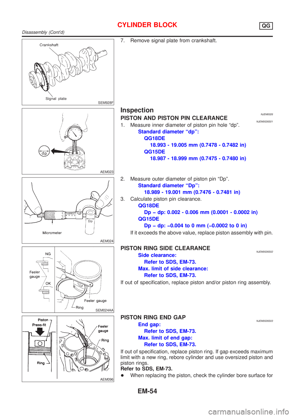
InspectionNJEM0026PISTON AND PISTON PIN CLEARANCENJEM0026S011. Measure inner diameter of piston pin hole ªdpº.
Standard diameter ªdpº:
QG18DE
18.993 - 19.005 mm (0.7478 - 0.7482 in)
QG15DE
18.987 - 18.999 mm (0.7475 - 0.7480 in)
AEM024
2. Measure outer diameter of piston pin ªDpº.
Standard diameter ªDpº:
18.989 - 19.001 mm (0.7476 - 0.7481 in)
3. Calculate piston pin clearance.
QG18DE
Dp þ dp: 0.002 - 0.006 mm (0.0001 - 0.0002 in)
QG15DE
Dp þ dp: þ0.004 to 0 mm (þ0.0002 to 0 in)
If it exceeds the above value, replace piston assembly with pin.
SEM024AA
PISTON RING SIDE CLEARANCENJEM0026S02Side clearance:
Refer to SDS, EM-73.
Max. limit of side clearance:
Refer to SDS, EM-73.
If out of specification, replace piston and/or piston ring assembly.
AEM096
PISTON RING END GAPNJEM0026S03End gap:
Refer to SDS, EM-73.
Max. limit of end gap:
Refer to SDS, EM-73.
If out of specification, replace piston ring. If gap exceeds maximum
limit with a new ring, rebore cylinder and use oversized piston and
piston rings.
Refer to SDS, EM-73.
+When replacing the piston, check the cylinder bore surface for
CYLINDER BLOCKQG
Disassembly (Cont'd)
EM-54
Page 133 of 2493
scratches or seizure. If scratches or seizure is found, hone or
replace the cylinder block.
SEM150B
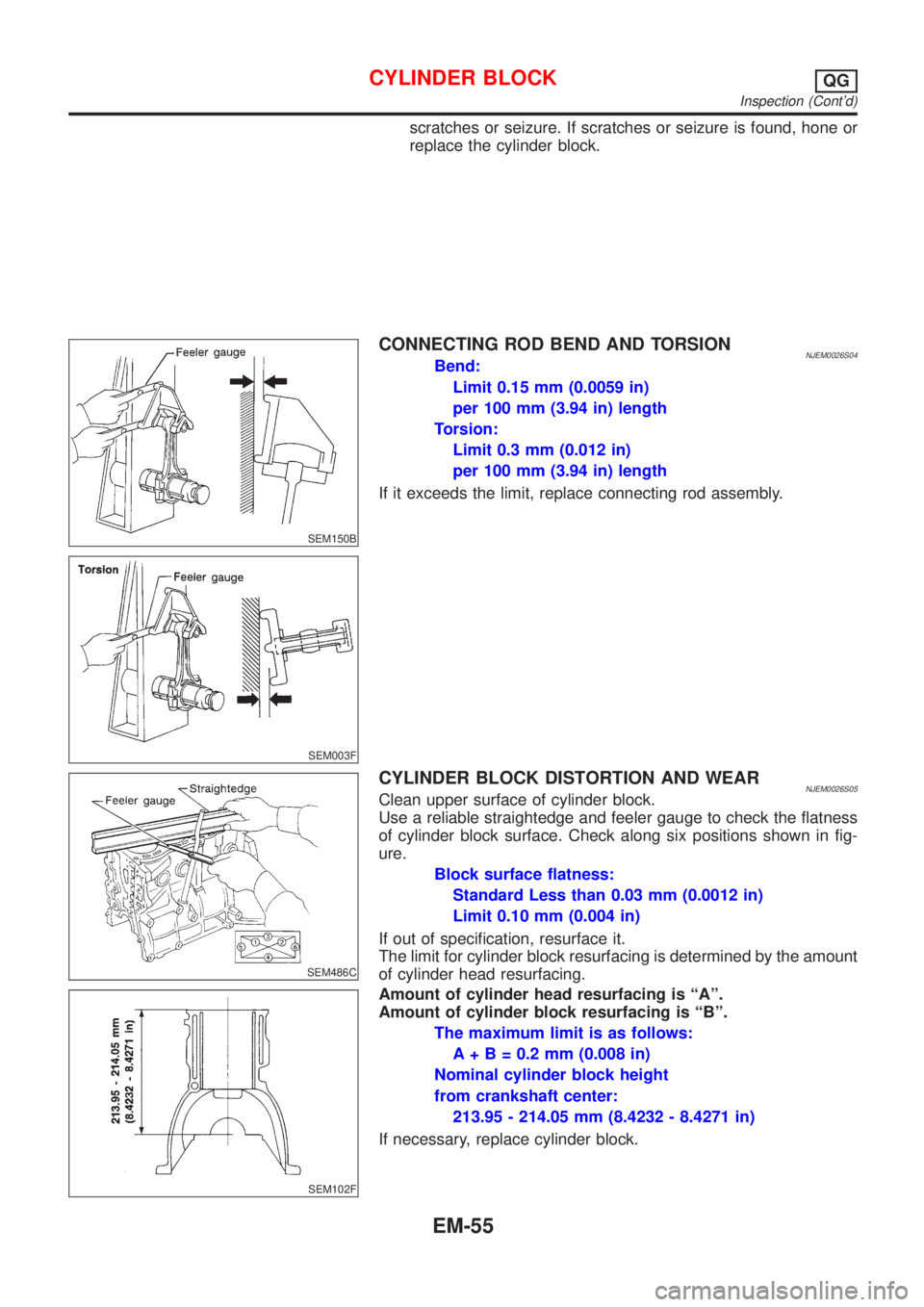
CONNECTING ROD BEND AND TORSIONNJEM0026S04Bend:
Limit 0.15 mm (0.0059 in)
per 100 mm (3.94 in) length
Torsion:
Limit 0.3 mm (0.012 in)
per 100 mm (3.94 in) length
If it exceeds the limit, replace connecting rod assembly.
SEM003F
SEM486C
CYLINDER BLOCK DISTORTION AND WEARNJEM0026S05Clean upper surface of cylinder block.
Use a reliable straightedge and feeler gauge to check the flatness
of cylinder block surface. Check along six positions shown in fig-
ure.
Block surface flatness:
Standard Less than 0.03 mm (0.0012 in)
Limit 0.10 mm (0.004 in)
If out of specification, resurface it.
The limit for cylinder block resurfacing is determined by the amount
of cylinder head resurfacing.
SEM102F
Amount of cylinder head resurfacing is ªAº.
Amount of cylinder block resurfacing is ªBº.
The maximum limit is as follows:
A + B = 0.2 mm (0.008 in)
Nominal cylinder block height
from crankshaft center:
213.95 - 214.05 mm (8.4232 - 8.4271 in)
If necessary, replace cylinder block.
CYLINDER BLOCKQG
Inspection (Cont'd)
EM-55