Page 1195 of 2493
parts. Apply petroleum jelly to protect O-rings and seals, or
hold bearings and washers in place during assembly. Do not
use grease.
+Extreme care should be taken to avoid damage to O-rings,
seals and gaskets when assembling.
+After overhaul, refill the transaxle with new ATF.
+When the A/T drain plug is removed, only some of the fluid is
drained. Old A/T fluid will remain in torque converter and ATF
cooling system.
Always follow the procedures under ªChanging A/T Fluidº in the
AT section when changing A/T fluid. Refer to ªChanging A/T
Fluidº, AT-15.
Service Notice or PrecautionsNJAT0247FAIL-SAFENJAT0247S01The TCM has an electronic Fail-Safe (limp home mode). This allows the vehicle to be driven even if a major
electrical input/output device circuit is damaged.
Under Fail-Safe, the vehicle always runs in third gear, even with a shift lever position of ª1º, ª2º or ªDº. The
customer may complain of sluggish or poor acceleration.
When the ignition key is turned ªONº following Fail-Safe operation, O/D OFF indicator lamp blinks for about
8 seconds. (For EXCEPT FOR EURO-OBD; ªSELF-DIAGNOSTIC PROCEDURE (WITHOUT CONSULT-II)º,
refer to AT-42 and for EURO-OBD; ªTCM SELF-DIAGNOSTIC PROCEDURE (No Tools)º, refer to AT-61.)
Fail-Safe may occur without electrical circuit damage if the vehicle is driven under extreme conditions (such
as excessive wheel spin followed by sudden braking). To recover normal shift pattern, turn the ignition key
ªOFFº for 5 seconds, then ªONº.
The blinking of the O/D OFF indicator lamp for about 8 seconds will appear only once and be cleared. The
customer may resume normal driving conditions.
Always follow the ªWORK FLOWº [Refer to AT-71 (Except for Euro-OBD), AT-76 (EURO-OBD).]
The SELF-DIAGNOSIS results will be as follows:
The first SELF-DIAGNOSIS will indicate damage to the vehicle speed sensor or the revolution sensor.
During the next SELF-DIAGNOSIS, performed after checking the sensor, no damages will be indicated.
TORQUE CONVERTER SERVICENJAT0247S02The torque converter should be replaced under any of the following conditions:
+External leaks in the hub weld area.
+Converter hub is scored or damaged.
+Converter pilot is broken, damaged or fits poorly into crankshaft.
+Steel particles are found after flushing the cooler and cooler lines.
+Pump is damaged or steel particles are found in the converter.
+Vehicle has TCC shudder and/or no TCC apply. Replace only after all hydraulic and electrical diagnoses
have been made. (Converter clutch material may be glazed.)
+Converter is contaminated with engine coolant containing antifreeze.
+Internal failure of stator roller clutch.
+Heavy clutch debris due to overheating (blue converter).
+Steel particles or clutch lining material found in fluid filter or on magnet when no internal parts in unit are
worn or damaged Ð indicates that lining material came from converter.
The torque converter should not be replaced if:
PRECAUTIONS
Precautions (Cont'd)
AT-9
Page 1254 of 2493
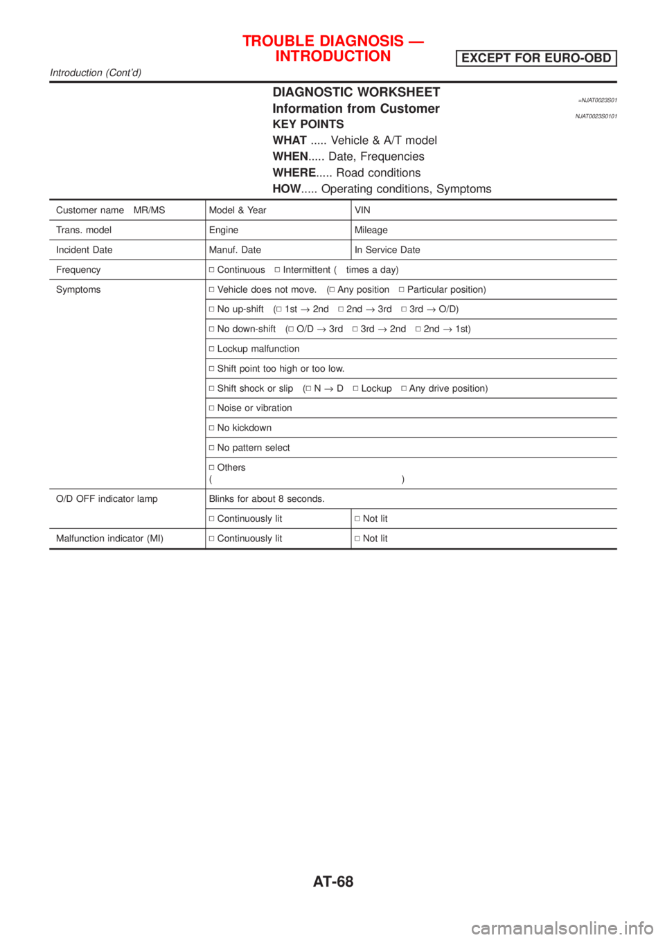
DIAGNOSTIC WORKSHEET=NJAT0023S01Information from CustomerNJAT0023S0101KEY POINTS
WHAT..... Vehicle & A/T model
WHEN..... Date, Frequencies
WHERE..... Road conditions
HOW..... Operating conditions, Symptoms
Customer name MR/MS Model & Year VIN
Trans. model Engine Mileage
Incident Date Manuf. Date In Service Date
FrequencyNContinuousNIntermittent ( times a day)
SymptomsNVehicle does not move. (NAny positionNParticular position)
NNo up-shift (N1st®2ndN2nd®3rdN3rd®O/D)
NNo down-shift (NO/D®3rdN3rd®2ndN2nd®1st)
NLockup malfunction
NShift point too high or too low.
NShift shock or slip (NN®DNLockupNAny drive position)
NNoise or vibration
NNo kickdown
NNo pattern select
NOthers
()
O/D OFF indicator lamp Blinks for about 8 seconds.
NContinuously litNNot lit
Malfunction indicator (MI)NContinuously litNNot lit
TROUBLE DIAGNOSIS Ð
INTRODUCTION
EXCEPT FOR EURO-OBD
Introduction (Cont'd)
AT-68
Page 1259 of 2493
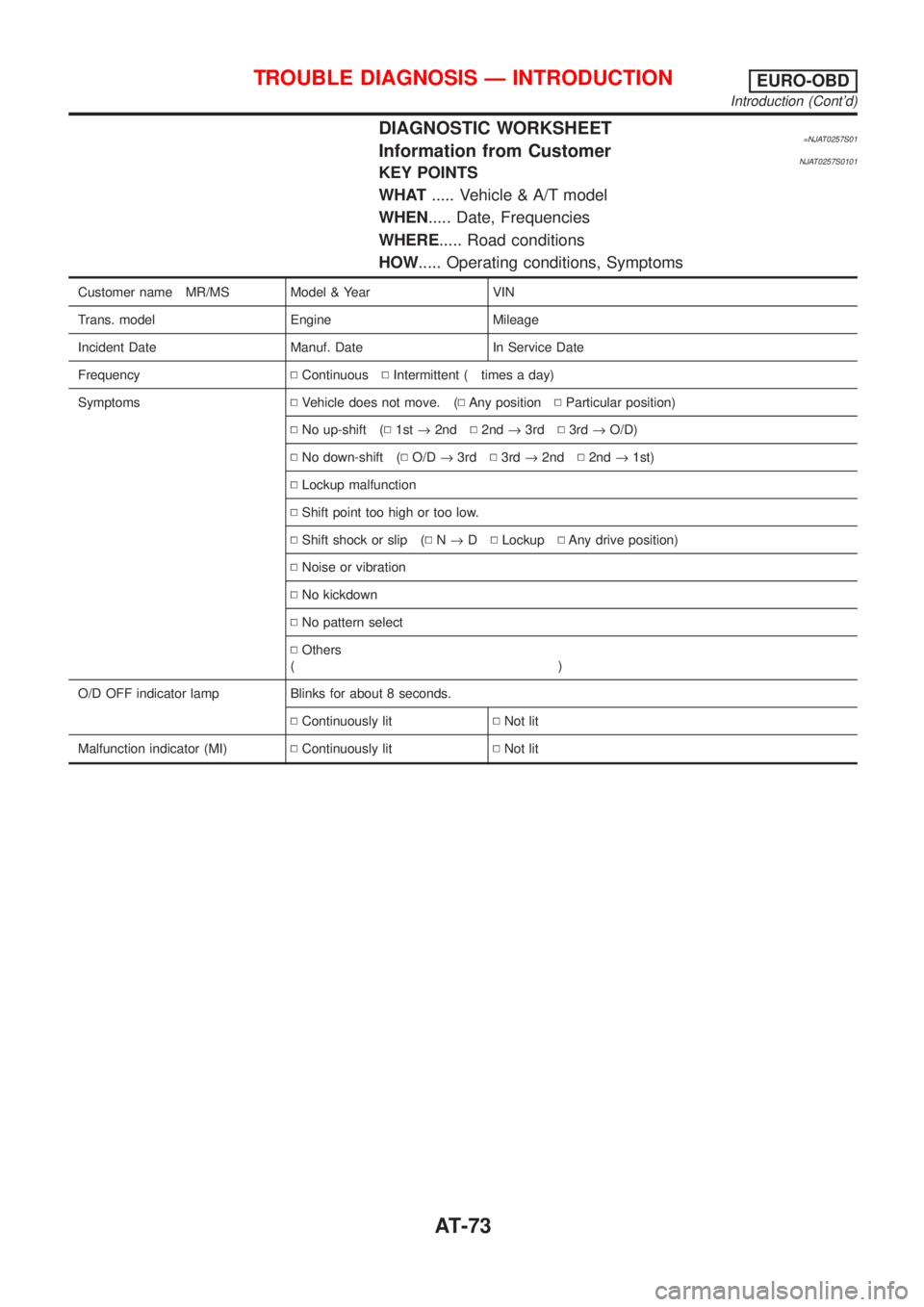
DIAGNOSTIC WORKSHEET=NJAT0257S01Information from CustomerNJAT0257S0101KEY POINTS
WHAT..... Vehicle & A/T model
WHEN..... Date, Frequencies
WHERE..... Road conditions
HOW..... Operating conditions, Symptoms
Customer name MR/MS Model & Year VIN
Trans. model Engine Mileage
Incident Date Manuf. Date In Service Date
FrequencyNContinuousNIntermittent ( times a day)
SymptomsNVehicle does not move. (NAny positionNParticular position)
NNo up-shift (N1st®2ndN2nd®3rdN3rd®O/D)
NNo down-shift (NO/D®3rdN3rd®2ndN2nd®1st)
NLockup malfunction
NShift point too high or too low.
NShift shock or slip (NN®DNLockupNAny drive position)
NNoise or vibration
NNo kickdown
NNo pattern select
NOthers
()
O/D OFF indicator lamp Blinks for about 8 seconds.
NContinuously litNNot lit
Malfunction indicator (MI)NContinuously litNNot lit
TROUBLE DIAGNOSIS Ð INTRODUCTIONEURO-OBD
Introduction (Cont'd)
AT-73
Page 1521 of 2493
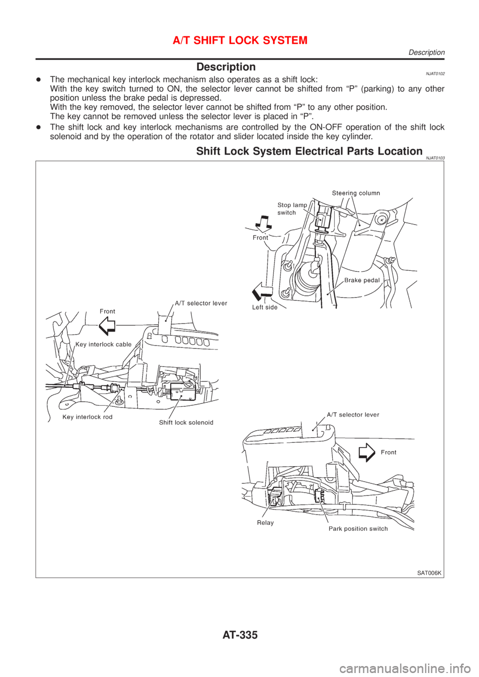
DescriptionNJAT0102+The mechanical key interlock mechanism also operates as a shift lock:
With the key switch turned to ON, the selector lever cannot be shifted from ªPº (parking) to any other
position unless the brake pedal is depressed.
With the key removed, the selector lever cannot be shifted from ªPº to any other position.
The key cannot be removed unless the selector lever is placed in ªPº.
+The shift lock and key interlock mechanisms are controlled by the ON-OFF operation of the shift lock
solenoid and by the operation of the rotator and slider located inside the key cylinder.
Shift Lock System Electrical Parts LocationNJAT0103
SAT006K
A/T SHIFT LOCK SYSTEM
Description
AT-335
Page 1523 of 2493
Diagnostic ProcedureNJAT0105SYMPTOM 1:
+Selector lever cannot be moved from ªPº position with key
in ON position and brake pedal applied.
+Selector lever can be moved from ªPº position with key in
ON position and brake pedal released.
+Selector lever can be moved from ªPº position when key
is removed from key cylinder.
SYMPTOM 2:
Ignition key cannot be removed when selector lever is set to
ªPº position. It can be removed when selector lever is set to
any position except ªPº.
1 CHECK KEY INTERLOCK CABLE
Check key interlock cable for damage.
OK or NG
OK©GO TO 2.
NG©Repair key interlock cable. Refer to AT-341.
2 CHECK SELECTOR LEVER POSITION
Check selector lever position for damage.
OK or NG
OK©GO TO 3.
NG©Check selector lever. Refer to ªON-VEHICLE SERVICE Ð PNP Switch and Control
Cable Adjustmentº, AT-344.
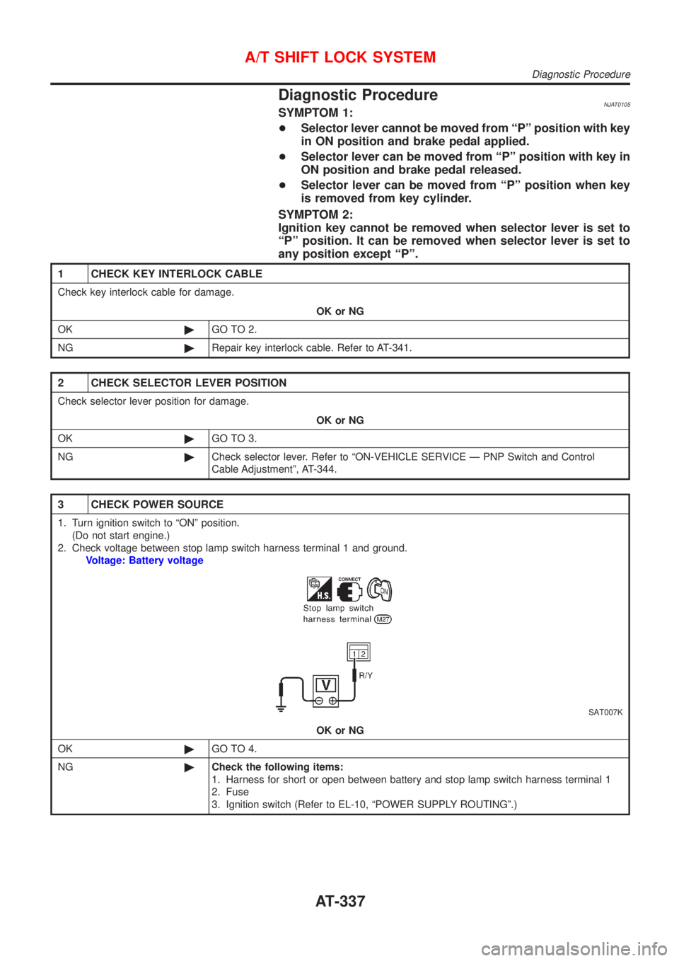
3 CHECK POWER SOURCE
1. Turn ignition switch to ªONº position.
(Do not start engine.)
2. Check voltage between stop lamp switch harness terminal 1 and ground.
Voltage: Battery voltage
SAT007K
OK or NG
OK©GO TO 4.
NG©Check the following items:
1. Harness for short or open between battery and stop lamp switch harness terminal 1
2. Fuse
3. Ignition switch (Refer to EL-10, ªPOWER SUPPLY ROUTINGº.)
A/T SHIFT LOCK SYSTEM
Diagnostic Procedure
AT-337
Page 1527 of 2493
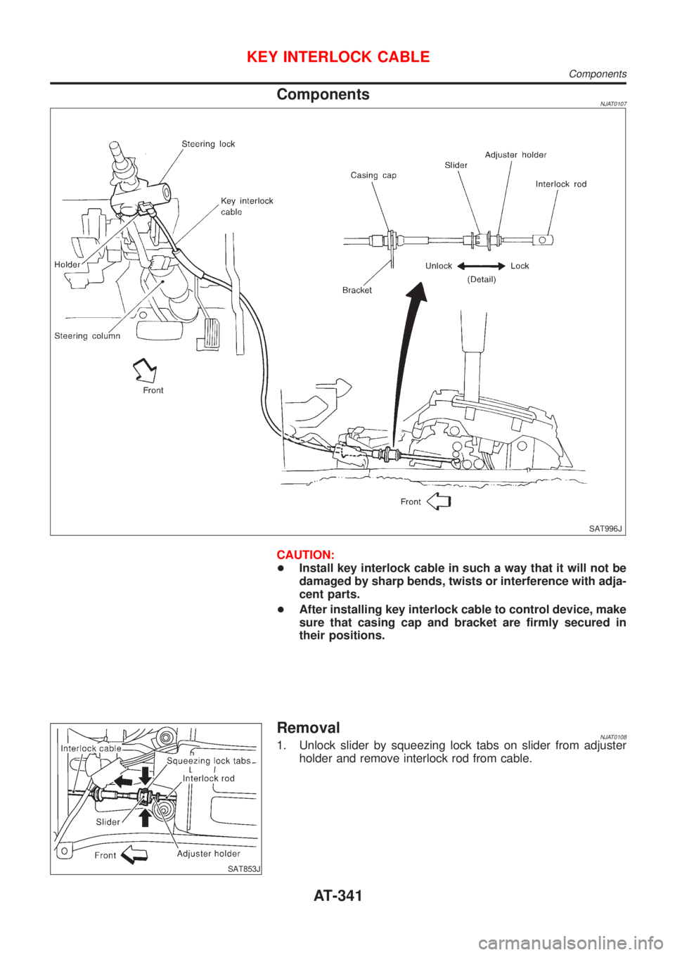
ComponentsNJAT0107
SAT996J
CAUTION:
+Install key interlock cable in such a way that it will not be
damaged by sharp bends, twists or interference with adja-
cent parts.
+After installing key interlock cable to control device, make
sure that casing cap and bracket are firmly secured in
their positions.
SAT853J
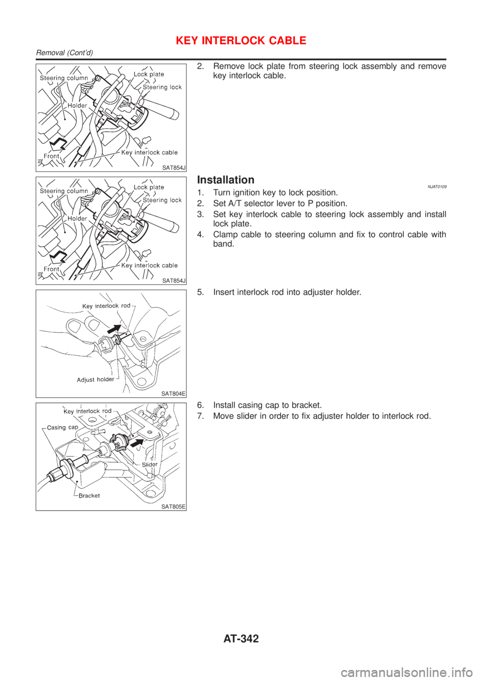
RemovalNJAT01081. Unlock slider by squeezing lock tabs on slider from adjuster
holder and remove interlock rod from cable.
KEY INTERLOCK CABLE
Components
AT-341
Page 1528 of 2493
SAT854J
2. Remove lock plate from steering lock assembly and remove
key interlock cable.
SAT854J
InstallationNJAT01091. Turn ignition key to lock position.
2. Set A/T selector lever to P position.
3. Set key interlock cable to steering lock assembly and install
lock plate.
4. Clamp cable to steering column and fix to control cable with
band.
SAT804E
5. Insert interlock rod into adjuster holder.
SAT805E
6. Install casing cap to bracket.
7. Move slider in order to fix adjuster holder to interlock rod.
KEY INTERLOCK CABLE
Removal (Cont'd)
AT-342
Page 1733 of 2493
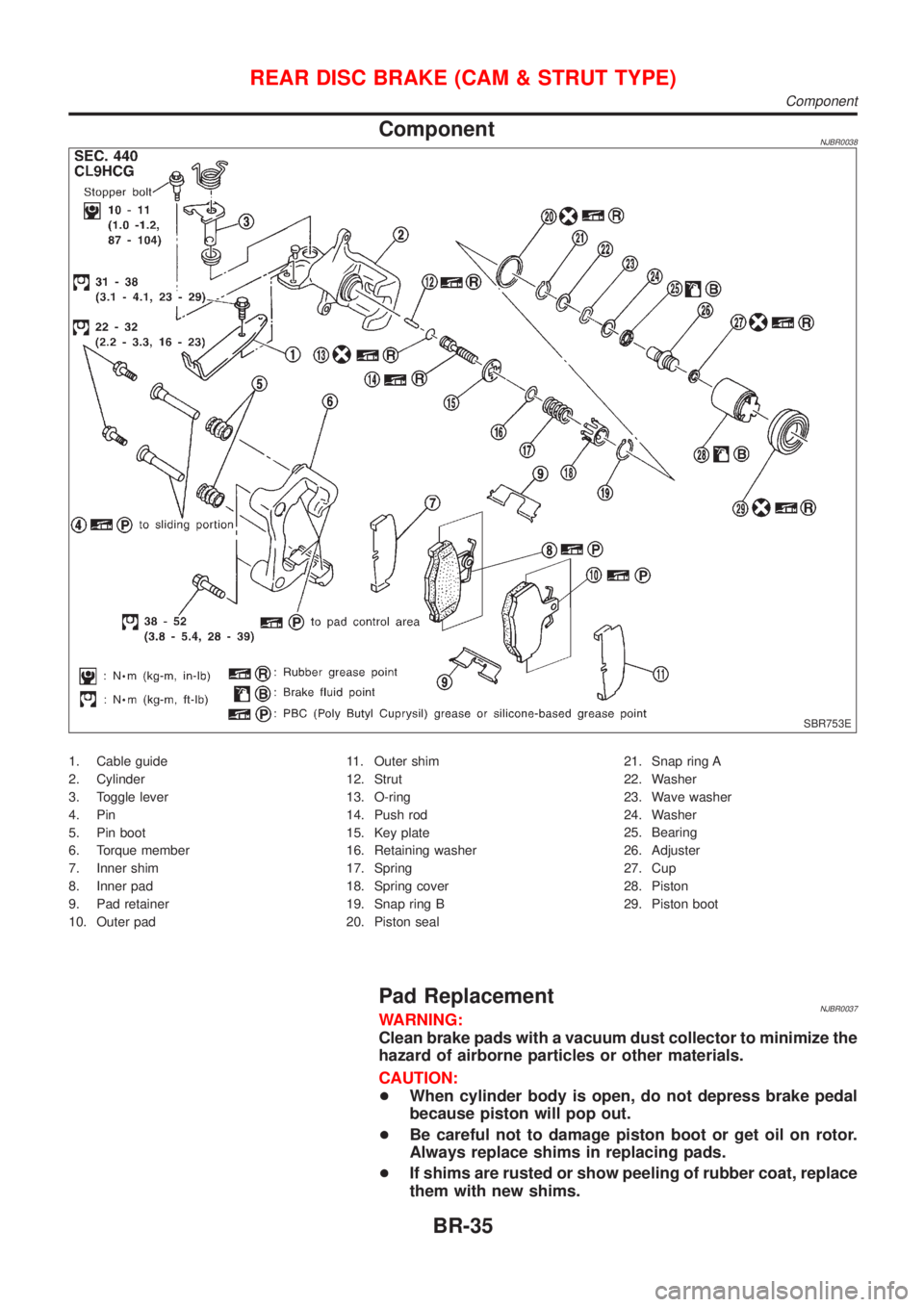
ComponentNJBR0038
SBR753E
1. Cable guide
2. Cylinder
3. Toggle lever
4. Pin
5. Pin boot
6. Torque member
7. Inner shim
8. Inner pad
9. Pad retainer
10. Outer pad11. Outer shim
12. Strut
13. O-ring
14. Push rod
15. Key plate
16. Retaining washer
17. Spring
18. Spring cover
19. Snap ring B
20. Piston seal21. Snap ring A
22. Washer
23. Wave washer
24. Washer
25. Bearing
26. Adjuster
27. Cup
28. Piston
29. Piston boot
Pad ReplacementNJBR0037WARNING:
Clean brake pads with a vacuum dust collector to minimize the
hazard of airborne particles or other materials.
CAUTION:
+When cylinder body is open, do not depress brake pedal
because piston will pop out.
+Be careful not to damage piston boot or get oil on rotor.
Always replace shims in replacing pads.
+If shims are rusted or show peeling of rubber coat, replace
them with new shims.
REAR DISC BRAKE (CAM & STRUT TYPE)
Component
BR-35