2001 NISSAN ALMERA N16 check oil
[x] Cancel search: check oilPage 123 of 2493
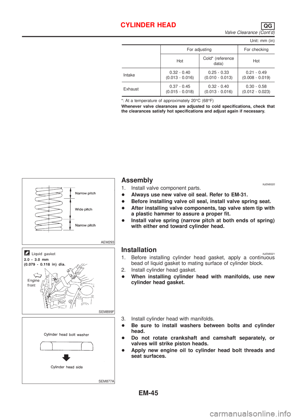
Unit: mm (in)
For adjusting For checking
HotCold* (reference
data)Hot
Intake0.32 - 0.40
(0.013 - 0.016)0.25 - 0.33
(0.010 - 0.013)0.21 - 0.49
(0.008 - 0.019)
Exhaust0.37 - 0.45
(0.015 - 0.018)0.32 - 0.40
(0.013 - 0.016)0.30 - 0.58
(0.012 - 0.023)
*: At a temperature of approximately 20ÉC (68ÉF)
Whenever valve clearances are adjusted to cold specifications, check that
the clearances satisfy hot specifications and adjust again if necessary.
AEM293
AssemblyNJEM00201. Install valve component parts.
+Always use new valve oil seal. Refer to EM-31.
+Before installing valve oil seal, install valve spring seat.
+After installing valve components, tap valve stem tip with
a plastic hammer to assure a proper fit.
+Install valve spring (narrow pitch at both ends of spring)
with either end toward cylinder head.
SEM899F
InstallationNJEM00211. Before installing cylinder head gasket, apply a continuous
bead of liquid gasket to mating surface of cylinder block.
2. Install cylinder head gasket.
+When installing cylinder head with manifolds, use new
cylinder head gasket.
SEM877A
3. Install cylinder head with manifolds.
+Be sure to install washers between bolts and cylinder
head.
+Do not rotate crankshaft and camshaft separately, or
valves will strike piston heads.
+Apply new engine oil to cylinder head bolt threads and
seat surfaces.
CYLINDER HEADQG
Valve Clearance (Cont'd)
EM-45
Page 125 of 2493
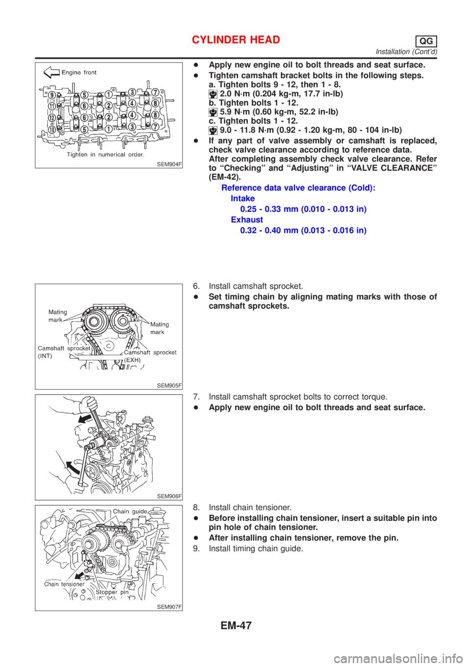
SEM904F
+Apply new engine oil to bolt threads and seat surface.
+Tighten camshaft bracket bolts in the following steps.
a. Tighten bolts9-12,then1-8.
2.0 N´m (0.204 kg-m, 17.7 in-lb)
b. Tighten bolts1-12.
5.9 N´m (0.60 kg-m, 52.2 in-lb)
c. Tighten bolts1-12.
9.0 - 11.8 N´m (0.92 - 1.20 kg-m, 80 - 104 in-lb)
+If any part of valve assembly or camshaft is replaced,
check valve clearance according to reference data.
After completing assembly check valve clearance. Refer
to ªCheckingº and ªAdjustingº in ªVALVE CLEARANCEº
(EM-42).
Reference data valve clearance (Cold):
Intake
0.25 - 0.33 mm (0.010 - 0.013 in)
Exhaust
0.32 - 0.40 mm (0.013 - 0.016 in)
SEM905F
6. Install camshaft sprocket.
+Set timing chain by aligning mating marks with those of
camshaft sprockets.
SEM906F
7. Install camshaft sprocket bolts to correct torque.
+Apply new engine oil to bolt threads and seat surface.
SEM907F
8. Install chain tensioner.
+Before installing chain tensioner, insert a suitable pin into
pin hole of chain tensioner.
+After installing chain tensioner, remove the pin.
9. Install timing chain guide.
CYLINDER HEADQG
Installation (Cont'd)
EM-47
Page 126 of 2493

SEM887F
10. Install cylinder head front cover.
+Apply liquid gasket to cylinder head front cover.
+Use Genuine Liquid Gasket or equivalent.
SEM889F
11. Install camshaft position sensor (PHASE).
SEM888F
12. Before installing rocker cover, apply a continuous bead of liq-
uid gasket to mating surface of cylinder head.
SEM105G
13. Install rocker cover with rocker cover gasket and tighten bolts
in numerical order as shown in the figure.
14. Install spark plugs.
15. Install ignition coils.
16. Install exhaust manifold.
17. Install intake manifold rear supports.
18. Connect vacuum hoses, fuel hoses, water hose, wire, harness,
connectors and so on.
19. Install front exhaust tube.
20. Install front undercovers.
21. Install air duct to intake manifold collector.
22. Drive belts.
For adjusting drive belt deflection, refer to ªCheckingº, EM-15.
23. Reinstall parts in reverse order of removal.
CYLINDER HEADQG
Installation (Cont'd)
EM-48
Page 159 of 2493
NJEM0051
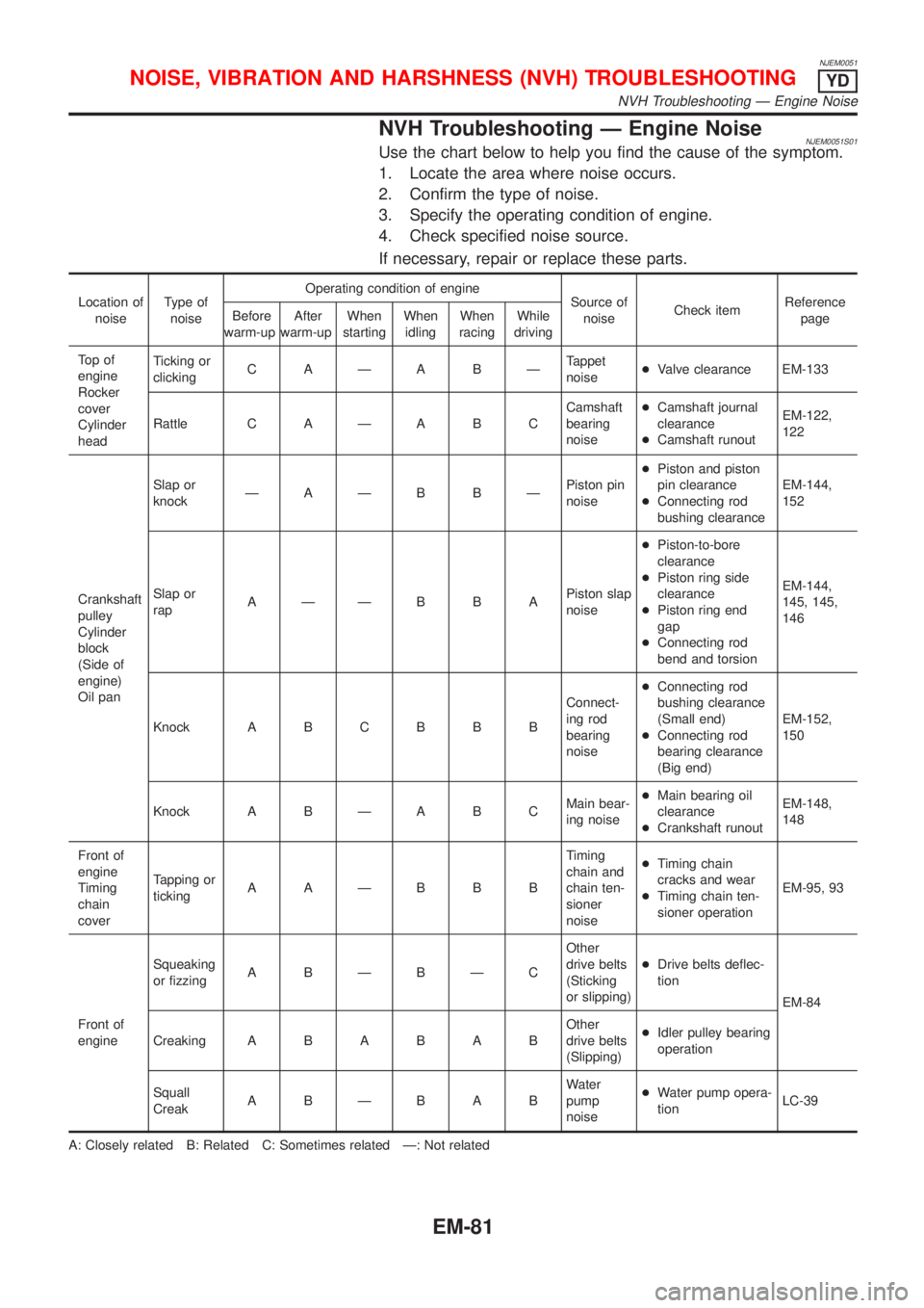
NVH Troubleshooting Ð Engine NoiseNJEM0051S01Use the chart below to help you find the cause of the symptom.
1. Locate the area where noise occurs.
2. Confirm the type of noise.
3. Specify the operating condition of engine.
4. Check specified noise source.
If necessary, repair or replace these parts.
Location of
noiseType of
noiseOperating condition of engine
Source of
noiseCheck itemReference
page Before
warm-upAfter
warm-upWhen
startingWhen
idlingWhen
racingWhile
driving
To p o f
engine
Rocker
cover
Cylinder
headTicking or
clickingC AÐA BÐTappet
noise+Valve clearance EM-133
Rattle C A Ð A B CCamshaft
bearing
noise+Camshaft journal
clearance
+Camshaft runoutEM-122,
122
Crankshaft
pulley
Cylinder
block
(Side of
engine)
Oil panSlap or
knockÐAÐB BÐPiston pin
noise+Piston and piston
pin clearance
+Connecting rod
bushing clearanceEM-144,
152
Slap or
rapAÐÐB B APiston slap
noise+Piston-to-bore
clearance
+Piston ring side
clearance
+Piston ring end
gap
+Connecting rod
bend and torsionEM-144,
145, 145,
146
Knock A B C B B BConnect-
ing rod
bearing
noise+Connecting rod
bushing clearance
(Small end)
+Connecting rod
bearing clearance
(Big end)EM-152,
150
Knock A B Ð A B CMain bear-
ing noise+Main bearing oil
clearance
+Crankshaft runoutEM-148,
148
Front of
engine
Timing
chain
coverTapping or
tickingAAÐBBBTiming
chain and
chain ten-
sioner
noise+Timing chain
cracks and wear
+Timing chain ten-
sioner operationEM-95, 93
Front of
engineSqueaking
or fizzingA BÐBÐCOther
drive belts
(Sticking
or slipping)+Drive belts deflec-
tion
EM-84
CreakingABABABOther
drive belts
(Slipping)+Idler pulley bearing
operation
Squall
CreakABÐBABWater
pump
noise+Water pump opera-
tionLC-39
A: Closely related B: Related C: Sometimes related Ð: Not related
NOISE, VIBRATION AND HARSHNESS (NVH) TROUBLESHOOTINGYD
NVH Troubleshooting Ð Engine Noise
EM-81
Page 163 of 2493

+If the belt deflection of the current belt is out of the ªLimit
for re-tighteningº, adjust to the ªAdjusted valueº.
+When checking belt deflection immediately after
installation, first adjust it to the specified value. Then,
after turning crankshaft two turns or more, re-adjust it to
the specified value to avoid variation in deflection
between pulleys.
+Make sure the belts are fully fitted into the pulley grooves
during installation.
+Handle with care to avoid smearing the belts with oil or
cooling water etc.
+Do not twist or bend the belts with strong force.
JEM251G
AIR CONDITIONER COMPRESSOR BELTNJEM0089S011. Remove RH splash cover (with undercover attached).
2. Loosen idler pulley lock nut (A).
3. Turn adjusting bolt (B) to adjust.
+Refer to EM-84, ªInspectionº for adjustment values.
4. Tighten lock nut (A).
Nut A:
: 31 - 39 N´m (3.1 - 4.0 kg-m, 23 - 28 ft-lb)
ALTERNATOR & WATER PUMP BELTNJEM0089S021. Loosen adjuster lock nut (C).
2. Loosen alternator fixing bolts (D) (each on front and rear).
3. Turn adjusting bolt (E) to adjust.
+Refer to EM-84, ªInspectionº for adjustment values.
4. Tighten nut (C) and bolt (D) in this order.
Nut C:
: 19 - 24 N´m (1.9 - 2.5 kg-m, 14 - 18 ft-lb)
Bolt D:
: 44 - 57 N´m (4.4 - 5.9 kg-m, 32 - 42 ft-lb)
RemovalNJEM00901. Loosen each belt. Refer to EM-84, ªAdjustmentº.
2. Remove air conditioner compressor belt.
3. Remove alternator & water pump belt.
DRIVE BELTSYD
Adjustment (Cont'd)
EM-85
Page 174 of 2493
JEM126G
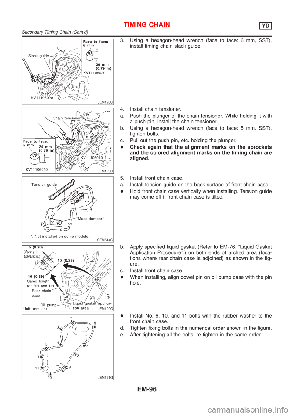
3. Using a hexagon-head wrench (face to face: 6 mm, SST),
install timing chain slack guide.
JEM125G
4. Install chain tensioner.
a. Push the plunger of the chain tensioner. While holding it with
a push pin, install the chain tensioner.
b. Using a hexagon-head wrench (face to face: 5 mm, SST),
tighten bolts.
c. Pull out the push pin, etc. holding the plunger.
+Check again that the alignment marks on the sprockets
and the colored alignment marks on the timing chain are
aligned.
SEM514G
5. Install front chain case.
a. Install tension guide on the back surface of front chain case.
+Hold front chain case vertically when installing. Tension guide
may come off if front chain case is tilted.
JEM129G
b. Apply specified liquid gasket (Refer to EM-76, ªLiquid Gasket
Application Procedureº.) on both ends of arched area (loca-
tions where rear chain case is adjoined) as shown in the fig-
ure.
c. Install front chain case.
+When installing, align dowel pin on oil pump case with the pin
hole.
JEM121G
+Install No. 6, 10, and 11 bolts with the rubber washer to the
front chain case.
d. Tighten fixing bolts in the numerical order shown in the figure.
e. After tightening all the bolts, re-tighten in the same order.
TIMING CHAINYD
Secondary Timing Chain (Cont'd)
EM-96
Page 181 of 2493
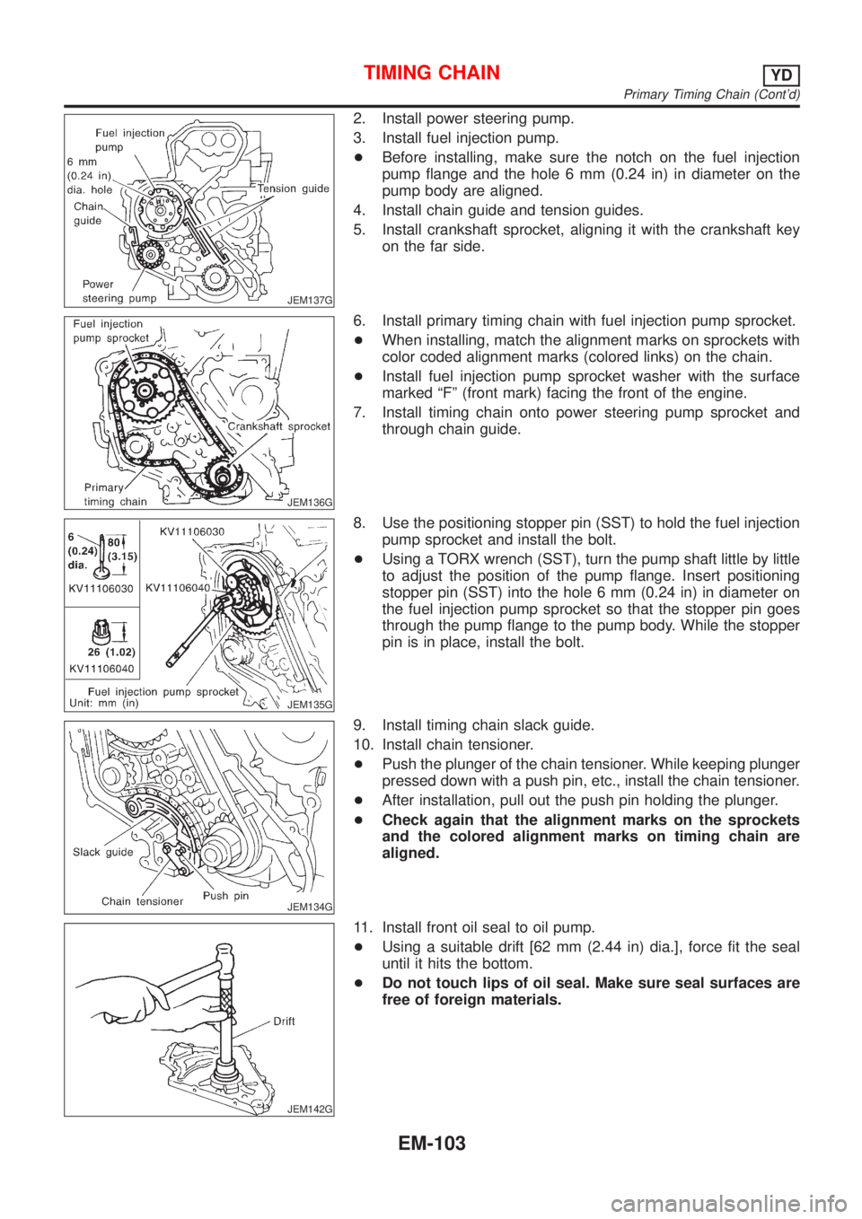
JEM137G
2. Install power steering pump.
3. Install fuel injection pump.
+Before installing, make sure the notch on the fuel injection
pump flange and the hole 6 mm (0.24 in) in diameter on the
pump body are aligned.
4. Install chain guide and tension guides.
5. Install crankshaft sprocket, aligning it with the crankshaft key
on the far side.
JEM136G
6. Install primary timing chain with fuel injection pump sprocket.
+When installing, match the alignment marks on sprockets with
color coded alignment marks (colored links) on the chain.
+Install fuel injection pump sprocket washer with the surface
marked ªFº (front mark) facing the front of the engine.
7. Install timing chain onto power steering pump sprocket and
through chain guide.
JEM135G
8. Use the positioning stopper pin (SST) to hold the fuel injection
pump sprocket and install the bolt.
+Using a TORX wrench (SST), turn the pump shaft little by little
to adjust the position of the pump flange. Insert positioning
stopper pin (SST) into the hole 6 mm (0.24 in) in diameter on
the fuel injection pump sprocket so that the stopper pin goes
through the pump flange to the pump body. While the stopper
pin is in place, install the bolt.
JEM134G
9. Install timing chain slack guide.
10. Install chain tensioner.
+Push the plunger of the chain tensioner. While keeping plunger
pressed down with a push pin, etc., install the chain tensioner.
+After installation, pull out the push pin holding the plunger.
+Check again that the alignment marks on the sprockets
and the colored alignment marks on timing chain are
aligned.
JEM142G
11. Install front oil seal to oil pump.
+Using a suitable drift [62 mm (2.44 in) dia.], force fit the seal
until it hits the bottom.
+Do not touch lips of oil seal. Make sure seal surfaces are
free of foreign materials.
TIMING CHAINYD
Primary Timing Chain (Cont'd)
EM-103
Page 182 of 2493
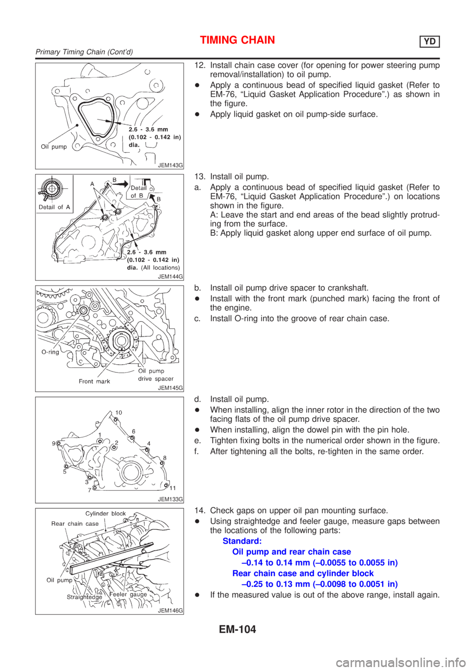
JEM143G
12. Install chain case cover (for opening for power steering pump
removal/installation) to oil pump.
+Apply a continuous bead of specified liquid gasket (Refer to
EM-76, ªLiquid Gasket Application Procedureº.) as shown in
the figure.
+Apply liquid gasket on oil pump-side surface.
JEM144G
13. Install oil pump.
a. Apply a continuous bead of specified liquid gasket (Refer to
EM-76, ªLiquid Gasket Application Procedureº.) on locations
shown in the figure.
A: Leave the start and end areas of the bead slightly protrud-
ing from the surface.
B: Apply liquid gasket along upper end surface of oil pump.
JEM145G
b. Install oil pump drive spacer to crankshaft.
+Install with the front mark (punched mark) facing the front of
the engine.
c. Install O-ring into the groove of rear chain case.
JEM133G
d. Install oil pump.
+When installing, align the inner rotor in the direction of the two
facing flats of the oil pump drive spacer.
+When installing, align the dowel pin with the pin hole.
e. Tighten fixing bolts in the numerical order shown in the figure.
f. After tightening all the bolts, re-tighten in the same order.
JEM146G
14. Check gaps on upper oil pan mounting surface.
+Using straightedge and feeler gauge, measure gaps between
the locations of the following parts:
Standard:
Oil pump and rear chain case
±0.14 to 0.14 mm (±0.0055 to 0.0055 in)
Rear chain case and cylinder block
±0.25 to 0.13 mm (±0.0098 to 0.0051 in)
+If the measured value is out of the above range, install again.
TIMING CHAINYD
Primary Timing Chain (Cont'd)
EM-104