Page 635 of 2493
Diagnostic ProcedureNJEC0491
1 CHECK COOLING FAN OPERATION
1. Start engine and let it idle.
2. Set temperature lever at full cold position.
3. Turn air conditioner switch ªONº.
4. Turn blower fan switch ªONº.
5. Make sure that cooling fans-1 and -2 operate.
SEC163BA
OK or NG
OK©GO TO 11.
NG©GO TO 2.
2 CHECK AIR CONDITIONER OPERATION
Is air conditioner operating?
(Check operation of compressor and blower motor.)
OK or NG
OK©GO TO 3.
NG©Check for failure of air conditioner to operate. Refer to HA section.
DTC P1217 OVERHEAT (COOLING SYSTEM)QG
Diagnostic Procedure
EC-339
Page 771 of 2493

JEF147Y
DescriptionNJEC0580The refrigerant pressure sensor is installed at the liquid tank of the
air conditioner system. The sensor uses an electrostatic volume
pressure transducer to convert refrigerant pressure to voltage. The
voltage signal is sent to ECM, and ECM controls cooling fan sys-
tem.
SEF099X
ECM Terminals and Reference ValueNJEC0581Specification data are reference values and are measured between each terminal and ground.
CAUTION:
Do not use ECM ground terminals when measuring input/output voltage. Doing so may result in dam-
age to the ECM's transistor. Use a ground other than ECM terminals, such as the ground.
TERMI-
NAL
NO.WIRE
COLORITEM CONDITION DATA (DC Voltage)
58 B Sensor's ground[Engine is running]
+Warm-up condition
+Idle speedApproximately 0V
74 R/LRefrigerant pressure
sensor[Engine is running]
+Warm-up condition
+Both A/C switch and blower switch are ªONº
(Compressor operates.)1.0 - 4.0V
111 R Sensor's power supply[Ignition switch ªONº]Approximately 5V
REFRIGERANT PRESSURE SENSORQG
Description
EC-475
Page 851 of 2493
![NISSAN ALMERA N16 2001 Electronic Repair Manual TERMI-
NAL
NO.WIRE
COLORITEM CONDITIONDATA (DC Voltage and Pulse
Signal)
204 L Air conditioner relay[Engine is running]
+Air conditioner switch is ªOFFºBATTERY VOLTAGE
(11 - 14V)
[Engine is running]](/manual-img/5/57351/w960_57351-850.png "NISSAN ALMERA N16 2001 Electronic Repair Manual TERMI-
NAL
NO.WIRE
COLORITEM CONDITIONDATA (DC Voltage and Pulse
Signal)
204 L Air conditioner relay[Engine is running]
+Air conditioner switch is ªOFFºBATTERY VOLTAGE
(11 - 14V)
[Engine is running]")
TERMI-
NAL
NO.WIRE
COLORITEM CONDITIONDATA (DC Voltage and Pulse
Signal)
204 L Air conditioner relay[Engine is running]
+Air conditioner switch is ªOFFºBATTERY VOLTAGE
(11 - 14V)
[Engine is running]
+Both air conditioner switch and blower fan
switch are ªONº
(Compressor is operating)Approximately 0.1V
214 W/B Glow relay Refer to ªGlow Control Systemº, EC-677.
218 B Sensors' ground[Engine is running]
+Warm-up condition
+Idle speedApproximately 0V
219 LG/R Cooling fan relay (Low)[Engine is running]
+Cooling fan is not operatingBATTERY VOLTAGE
(11 - 14V)
[Engine is running]
+Cooling fan is operatingApproximately 0.1V
221 LG/B Cooling fan relay (High)[Engine is running]
+Cooling fan is not operating
+Cooling fan is operating at low speedBATTERY VOLTAGE
(11 - 14V)
[Engine is running]
+Cooling fan is operating at high speedApproximately 0.1V
223 WMass air flow sensor
power supply[Ignition switch ªONº]Approximately 5V
224 R Mass air flow sensor[Engine is running]
+Warm-up condition
+Idle speed1.5 - 2.0V
313 L/WElectronic control fuel
injection pump[Engine is running]
+Warm-up condition
+Idle speedApproximately 0.1V
314 L/RElectronic control fuel
injection pump[Engine is running]
+Warm-up condition
+Idle speedApproximately 0.4V
316 PUElectronic control fuel
injection pump[Engine is running]
+Warm-up condition
+Idle speedApproximately 2.5V
317 PElectronic control fuel
injection pump[Engine is running]
+Warm-up condition
+Idle speedApproximately 2.5V
325 G ECM relay (Self-shutoff)[Ignition switch ªONº]
[Ignition switch ªOFFº]
+For a few seconds after turning ignition switch
ªOFFºApproximately 0.25V
[Ignition switch ªOFFº]
+A few seconds passed after turning ignition
switch ªOFFºBATTERY VOLTAGE
(11 - 14V)
331 ORCrankshaft position sen-
sor (TDC) ground[Engine is running]
+Warm-up condition
+Idle speedApproximately 0V
334 B/REngine coolant tempera-
ture sensor ground[Ignition switch ªONº]Approximately 0V
TROUBLE DIAGNOSIS Ð GENERAL DESCRIPTIONYD
ECM Terminals and Reference Value (Cont'd)
EC-555
Page 852 of 2493
![NISSAN ALMERA N16 2001 Electronic Repair Manual TERMI-
NAL
NO.WIRE
COLORITEM CONDITIONDATA (DC Voltage and Pulse
Signal)
337
338
350
351W/L
PU/W
GY
OR/BEGR volume control
valve[Engine is running]
+Warm-up condition
+Idle speed0.1 - 14V
(Voltage sig](/manual-img/5/57351/w960_57351-851.png "NISSAN ALMERA N16 2001 Electronic Repair Manual TERMI-
NAL
NO.WIRE
COLORITEM CONDITIONDATA (DC Voltage and Pulse
Signal)
337
338
350
351W/L
PU/W
GY
OR/BEGR volume control
valve[Engine is running]
+Warm-up condition
+Idle speed0.1 - 14V
(Voltage sig")
TERMI-
NAL
NO.WIRE
COLORITEM CONDITIONDATA (DC Voltage and Pulse
Signal)
337
338
350
351W/L
PU/W
GY
OR/BEGR volume control
valve[Engine is running]
+Warm-up condition
+Idle speed0.1 - 14V
(Voltage signals of each ECM
terminals differ according to the
control position of EGR volume
control valve.)
344 WCrankshaft position sen-
sor (TDC)[Engine is running]
+Warm-up condition
+Idle speedApproximately 0V
SEF333Y
[Engine is running]
+Warm-up condition
+Engine speed is 2,000 rpmApproximately 0V
SEF334Y
347 L/BEngine coolant tempera-
ture sensor[Engine is running]Approximately 0 - 4.8V
Output voltage varies with
engine coolant temperature
403 R/L Air conditioner switch[Engine is running]
+Air conditioner switch is ªOFFºBATTERY VOLTAGE
(11 - 14V)
[Engine is running]
+Both air conditioner switch and blower fan
switch are ªONº
(Compressor is operating)Approximately 0.1V
405 R/G Stop lamp switch[Ignition switch ªONº]
+Brake pedal fully releasedApproximately 0V
[Ignition switch ªONº]
+Brake pedal depressedBATTERY VOLTAGE
(11 - 14V)
416 Y/BBrake pedal position
switch[Ignition switch ªONº]
+Brake pedal fully releasedBATTERY VOLTAGE
(11 - 14V)
[Ignition switch ªONº]
+Brake pedal depressedApproximately 0V
TROUBLE DIAGNOSIS Ð GENERAL DESCRIPTIONYD
ECM Terminals and Reference Value (Cont'd)
EC-556
Page 914 of 2493

DescriptionNJEC0660SYSTEM DESCRIPTIONNJEC0660S01
Sensor Input signal to ECM ECM function Actuator
Vehicle speed sensor Vehicle speed
Cooling fan
controlCooling fan relay Engine coolant temperature sensor Engine coolant temperature
Air conditioner switch Air conditioner ªONº signal
The ECM controls the cooling fan corresponding to the vehicle speed, engine coolant temperature, air condi-
tioner ON signal. The control system has 3-step control [HIGH/LOW/OFF].
OPERATIONNJEC0660S02
SEF421Z
CONSULT-II Reference Value in Data Monitor
Mode
NJEC0661Specification data are reference values.
MONITOR ITEM CONDITION SPECIFICATION
AIR COND SIG+Engine: After warming up, idle
the engineAir conditioner switch: OFF OFF
Air conditioner switch: ON
(Compressor operates.)ON
COOLING FAN+When cooling fan is stopped. OFF
+When cooling fans operate at low speed. LOW
+When cooling fans operate at high speed. HIGH
ECM Terminals and Reference ValueNJEC0662Specification data are reference values and are measured between each terminal and ground.
CAUTION:
Do not use ECM ground terminals when measuring input/output voltage. Doing so may result in dam-
age to the ECM's transistor. Use a ground other than ECM terminals, such as the ground.
TERMI-
NAL
NO.WIRE
COLORITEM CONDITION DATA(DC Voltage)
219 LG/R Cooling fan relay (Low)[Engine is running]
+Cooling fans are not operatingBATTERY VOLTAGE
(11 - 14V)
[Engine is running]
+Cooling fans are operatingApproximately 0.1V
DTC P1217 OVER HEATYD
Description
EC-618
Page 1077 of 2493
SMT940D
SMT951D
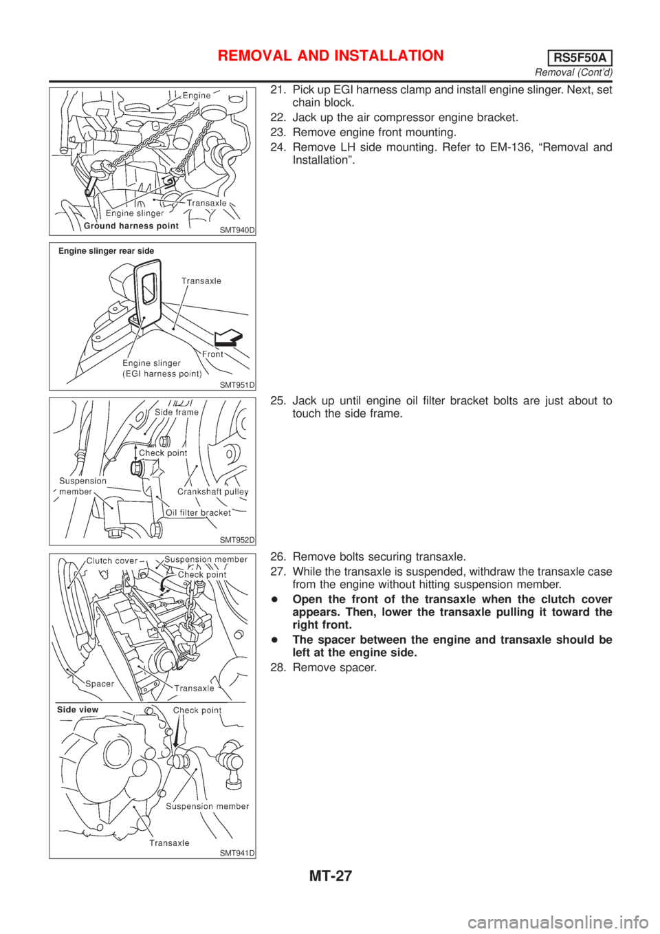
21. Pick up EGI harness clamp and install engine slinger. Next, set
chain block.
22. Jack up the air compressor engine bracket.
23. Remove engine front mounting.
24. Remove LH side mounting. Refer to EM-136, ªRemoval and
Installationº.
SMT952D
25. Jack up until engine oil filter bracket bolts are just about to
touch the side frame.
SMT941D
26. Remove bolts securing transaxle.
27. While the transaxle is suspended, withdraw the transaxle case
from the engine without hitting suspension member.
+Open the front of the transaxle when the clutch cover
appears. Then, lower the transaxle pulling it toward the
right front.
+The spacer between the engine and transaxle should be
left at the engine side.
28. Remove spacer.
REMOVAL AND INSTALLATIONRS5F50A
Removal (Cont'd)
MT-27
Page 1675 of 2493
Tool name Description
Spring compressor
NT717
Removing and installing coil spring
FRONT SUSPENSION
Preparation (Cont'd)
SU-3
Page 1682 of 2493
SFA956A
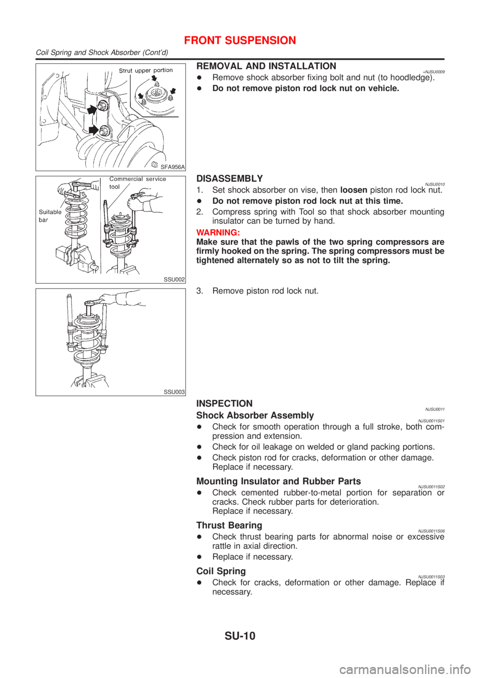
REMOVAL AND INSTALLATION=NJSU0009+Remove shock absorber fixing bolt and nut (to hoodledge).
+Do not remove piston rod lock nut on vehicle.
SSU002
DISASSEMBLYNJSU00101. Set shock absorber on vise, thenloosenpiston rod lock nut.
+Do not remove piston rod lock nut at this time.
2. Compress spring with Tool so that shock absorber mounting
insulator can be turned by hand.
WARNING:
Make sure that the pawls of the two spring compressors are
firmly hooked on the spring. The spring compressors must be
tightened alternately so as not to tilt the spring.
SSU003
3. Remove piston rod lock nut.
INSPECTIONNJSU0011Shock Absorber AssemblyNJSU0011S01+Check for smooth operation through a full stroke, both com-
pression and extension.
+Check for oil leakage on welded or gland packing portions.
+Check piston rod for cracks, deformation or other damage.
Replace if necessary.
Mounting Insulator and Rubber PartsNJSU0011S02+Check cemented rubber-to-metal portion for separation or
cracks. Check rubber parts for deterioration.
Replace if necessary.
Thrust BearingNJSU0011S06+Check thrust bearing parts for abnormal noise or excessive
rattle in axial direction.
+Replace if necessary.
Coil SpringNJSU0011S03+Check for cracks, deformation or other damage. Replace if
necessary.
FRONT SUSPENSION
Coil Spring and Shock Absorber (Cont'd)
SU-10