Page 1907 of 2493

Removal and Installation (Hatchback)NJBT0034+When removing or installing back door, place a cloth or other padding on back door. This prevents vehicle
body from being scratched.
+Bumper fascia is made of plastic. Do not use excessive force and be sure to keep oil away from it.
+Back door adjustment: Adjust at hinge-back door portion for proper back door fit.
+Back door lock system adjustment: Adjust striker so that it is in the center of the lock. After adjustment,
check back door lock operation.
+After installation, make sure that back door and fuel filler lid open smoothly.
HFor Wiring Diagram, refer to EL, ªTRUNK LID OPENERº.
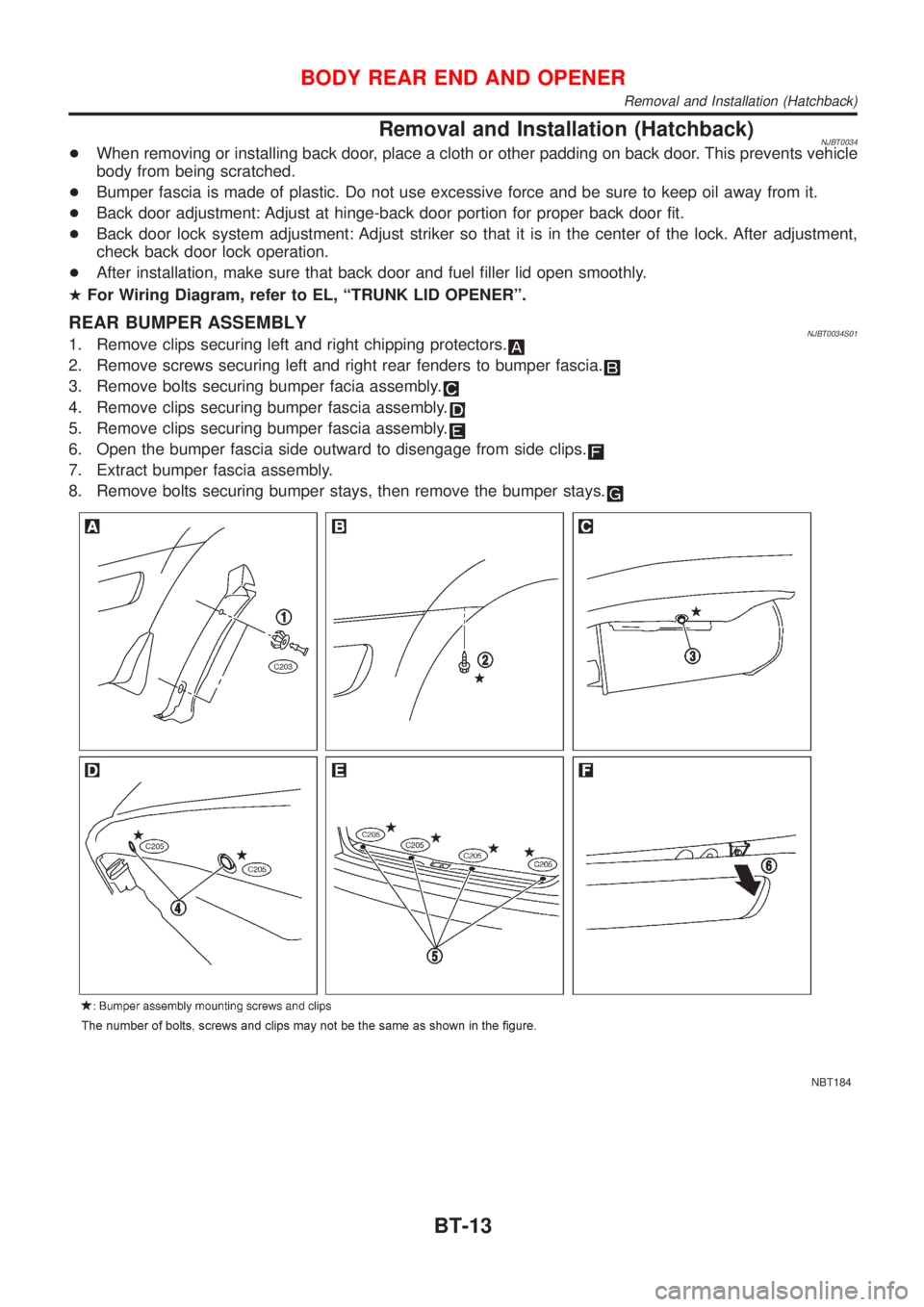
REAR BUMPER ASSEMBLYNJBT0034S011. Remove clips securing left and right chipping protectors.
2. Remove screws securing left and right rear fenders to bumper fascia.
3. Remove bolts securing bumper facia assembly.
4. Remove clips securing bumper fascia assembly.
5. Remove clips securing bumper fascia assembly.
6. Open the bumper fascia side outward to disengage from side clips.
7. Extract bumper fascia assembly.
8. Remove bolts securing bumper stays, then remove the bumper stays.
NBT184
BODY REAR END AND OPENER
Removal and Installation (Hatchback)
BT-13
Page 1950 of 2493
Removal and InstallationNJBT0018+When removing or installing the seat trim, carefully handle it to keep dirt out and avoid damage.
HFor Wiring Diagram, refer to EL-163, ªWiring Diagram Ð HEATED SEAT к.
CAUTION:
+Before removing the front seat, turn the ignition switch off, disconnect both battery cables and wait
at least 3 minutes.
+Do not drop, tilt, or bump the side air bag module installed in the seat. Always handle it with care.
+Disconnect the side air bag harness connector and heated seat harness connector from under the
seat before removing the seat.
+Disconnect the side air bag harness connector before removing the seat back. Refer to RS-33,
ªFront Side Air Bag Moduleº for details.
FRONT SEAT
Removal and Installation
BT-56
Page 1952 of 2493
Heated SeatNJBT0036HFor Wiring Diagram, refer to EL-163, ªHEATED SEATº for details.
SBT014A
Active Head RestraintNJBT0032The active head restraint system is designed so that the headrest
instantaneously moves towards the front upper direction by utiliz-
ing the force at the seatback during a rear-end collision.
As a result, the occupant's head is protected from being
overextended, reducing the chance for neck injury as much as
possible.
Seat with active head restraint have the labels shown in figures at
left.
SBT888
OPERATION OUTLINENJBT0032S01When the seatback receives a sharp backward force during a rear-
end collision, the input plate moves with the link rotating center as
a pivot. The headrest will then move towards the front upper direc-
tion with the center of the sliding roller as a pivot.
As the backward force on the seat back is eliminated, spring ten-
sion returns the headrest to its original position.
FRONT SEAT
Heated Seat
BT-58
Page 1966 of 2493
Removal and InstallationNJBT0024CAUTION:
Be careful not to scratch door rearview mirror body.
HFor Wiring Diagram, refer to EL-167, ªDOOR MIRRORº for details.
1. Remove front corner of door inner cover.
2. Disconnect door mirror harness connector.
3. Remove bolts securing door mirror assembly.
4. Remove the mirror glass. Do not insert flat-bladed screwdriver too far.
NBT205
DOOR MIRROR
Removal and Installation
BT-72
Page 1973 of 2493

HEATER &
AIR CONDITIONER
SECTION
HA
CONTENTS
PRECAUTIONS...............................................................2
Supplemental Restraint System (SRS)²AIR
BAG²and²SEAT BELT PRE-TENSIONER²...............2
Precautions for Working with HFC-134a (R-134a) .....2
General Refrigerant Precautions .................................2
Precautions for Refrigerant Connection ......................3
Precautions for Servicing Compressor ........................5
Precautions for Service Equipment .............................6
Wiring Diagrams and Trouble Diagnosis .....................8
PREPARATION...............................................................9
Special Service Tools ..................................................9
HFC-134a (R-134a) Service Tools and
Equipment .................................................................. 11
DESCRIPTION...............................................................13
Refrigeration System .................................................13
CSV613 Variable Displacement Compressor............14
Component Layout ....................................................18
Control Operation ......................................................19
Discharge Air Flow.....................................................20
System Description ....................................................21
TROUBLE DIAGNOSES................................................22
Component Location..................................................22
Wiring Diagram - Heater............................................24
Circuit Diagram - Air Conditioner...............................26
Wiring Diagram - A/C, M - .........................................27
How to Perform Trouble Diagnoses for Quick
and Accurate Repair ..................................................39
Operational Check .....................................................40
Intake Door ................................................................42
Mode Door .................................................................46Air Mix Door ...............................................................48
Max Hot Door (For Scandinavia and Cold Spec
Models) ......................................................................50
Blower Motor..............................................................54
Magnet Clutch............................................................61
Insufficient Cooling ....................................................74
Insufficient Heating ....................................................82
Noise ..........................................................................83
SERVICE PROCEDURE................................................84
HFC-134a (R-134a) Service Procedure ....................84
Maintenance of Lubricant Quantity in
Compressor ...............................................................86
Compressor ...............................................................89
Compressor Clutch - CSV613 (CALSONIC
make) .........................................................................90
Heater & Cooling Unit (Heater Core) ........................94
A/C Evaporator ..........................................................94
Blower Unit ................................................................95
Refrigerant Lines .......................................................97
Belt ...........................................................................101
Idle Air Control Valve (IACV) - Auxiliary Air
Control (AAC) Valve ................................................102
Ventilation Air Filter ..................................................102
SERVICE DATA AND SPECIFICATIONS (SDS).......103
Compressor .............................................................103
Lubricant ..................................................................103
Refrigerant ...............................................................103
Engine Idling Speed (When A/C is On)...................103
Belt Tension .............................................................103
Page 1980 of 2493
Wiring Diagrams and Trouble DiagnosisNJHA0118When you read wiring diagrams, refer to the following:
+GI-12, ªHOW TO READ WIRING DIAGRAMSº
+Sedan: EL-23 (QG), EL-0 (YD), Hatchback: EL-12, ªWiring
Diagram РPOWER к.
When you perform trouble diagnosis, refer to the following:
+GI-32, ªHOW TO FOLLOW TROUBLE DIAGNOSESº
+GI-21, ªHOW TO PERFORM EFFICIENT DIAGNOSIS FOR
AN ELECTRICAL INCIDENTº
PRECAUTIONS
Wiring Diagrams and Trouble Diagnosis
HA-8
Page 1996 of 2493
Wiring Diagram Ð HeaterNJHA0202EXCEPT LHD MODELS WITH MAX HOT DOOR WITHOUT HEATED SEATNJHA0202S02
YHA361
TROUBLE DIAGNOSES
Wiring Diagram Ð Heater
HA-24
Page 1997 of 2493
LHD MODELS WITH MAX HOT DOOR WITHOUT HEATED SEATNJHA0202S03
YHA362
TROUBLE DIAGNOSES
Wiring Diagram Ð Heater (Cont'd)
HA-25