Page 1754 of 2493
YBR226
DESCRIPTIONABS
Wiring Diagram Ð ABS Ð (Cont'd)
BR-56
Page 1755 of 2493
YBR227
DESCRIPTIONABS
Wiring Diagram Ð ABS Ð (Cont'd)
BR-57
Page 1781 of 2493

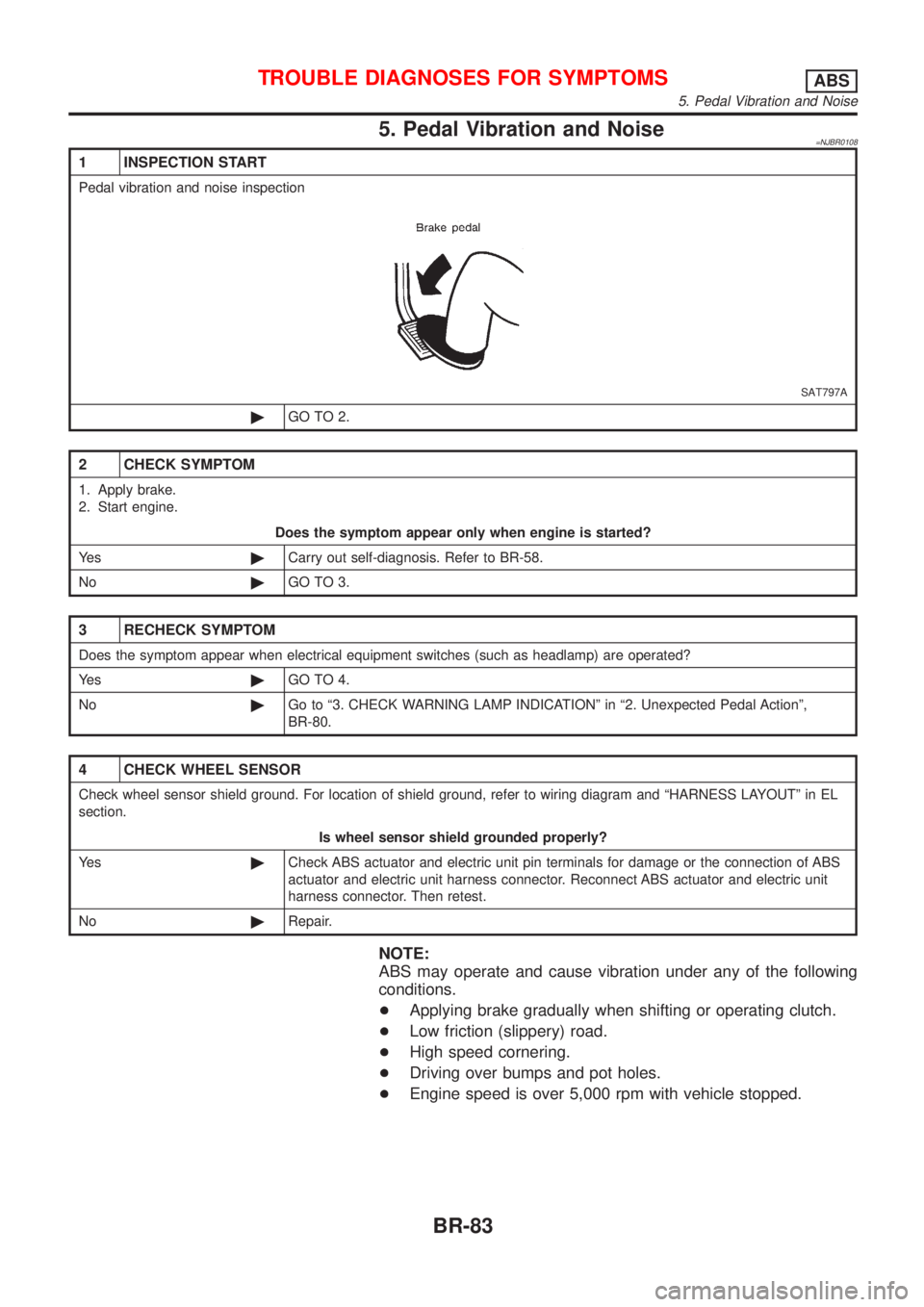
5. Pedal Vibration and Noise=NJBR0108
1 INSPECTION START
Pedal vibration and noise inspection
SAT797A
©GO TO 2.
2 CHECK SYMPTOM
1. Apply brake.
2. Start engine.
Does the symptom appear only when engine is started?
Ye s©Carry out self-diagnosis. Refer to BR-58.
No©GO TO 3.
3 RECHECK SYMPTOM
Does the symptom appear when electrical equipment switches (such as headlamp) are operated?
Ye s©GO TO 4.
No©Go to ª3. CHECK WARNING LAMP INDICATIONº in ª2. Unexpected Pedal Actionº,
BR-80.
4 CHECK WHEEL SENSOR
Check wheel sensor shield ground. For location of shield ground, refer to wiring diagram and ªHARNESS LAYOUTº in EL
section.
Is wheel sensor shield grounded properly?
Ye s©Check ABS actuator and electric unit pin terminals for damage or the connection of ABS
actuator and electric unit harness connector. Reconnect ABS actuator and electric unit
harness connector. Then retest.
No©Repair.
NOTE:
ABS may operate and cause vibration under any of the following
conditions.
+Applying brake gradually when shifting or operating clutch.
+Low friction (slippery) road.
+High speed cornering.
+Driving over bumps and pot holes.
+Engine speed is over 5,000 rpm with vehicle stopped.
TROUBLE DIAGNOSES FOR SYMPTOMSABS
5. Pedal Vibration and Noise
BR-83
Page 1821 of 2493

RESTRAINT SYSTEM
SECTION
RS
CONTENTS
SEAT BELTS...................................................................3
Precautions ..................................................................3
SUPPLEMENTAL RESTRAINT SYSTEM (SRS)
²AIR BAG²AND²SEAT BELT PRE-TENSIONER²
........3
PRECAUTION FOR SEAT BELT SERVICE..................3
Maintenance ................................................................4
Front Seat Belt.............................................................5
REMOVAL AND INSTALLATION/4-DOOR SEDAN.......5
REMOVAL AND INSTALLATION/5-DOOR
HATCHBACK
.............................................................7
REMOVAL AND INSTALLATION/3-DOOR
HATCHBACK
.............................................................9
Rear Seat Belt ........................................................... 11
REMOVAL AND INSTALLATION/4-DOOR SEDAN
WITH 2-POINT TYPE REAR CENTER SEAT BELT
.... 11
REMOVAL AND INSTALLATION/4-DOOR SEDAN
WITH 3-POINT TYPE REAR CENTER SEAT BELT
....13
REMOVAL AND INSTALLATION/HATCHBACK
WITH 3-POINT TYPE REAR CENTER SEAT
.............15
ISO Fix Child Restraint Anchor .................................18
REMOVAL AND INSTALLATION...............................18
Tether Anchor Plate ...................................................19
REMOVAL AND INSTALLATION...............................19
SUPPLEMENTAL RESTRAINT SYSTEM (SRS).........20
Precautions ................................................................20
SUPPLEMENTAL RESTRAINT SYSTEM (SRS)
²AIR BAG²AND²SEAT BELT PRE-TENSIONER²
......20
PRECAUTIONS FOR SRS²AIR BAG²AND²SEAT
BELT PRE-TENSIONER²SERVICE
...........................20
WIRING DIAGRAMS AND TROUBLE DIAGNOSIS.....20
Preparation ................................................................21
SPECIAL SERVICE TOOLS......................................21
COMMERCIAL SERVICE TOOL................................22
SRS Configuration .....................................................22
Seat Belt Pre-tensioner with Load Limiter.................23
Built-in Type Side Air Bag..........................................23
SRS Component Parts Location ...............................24
Maintenance Items ....................................................25
Diagnosis Sensor Unit ...............................................26
REMOVAL AND INSTALLATION...............................26
Front Seat Belt Pre-tensioner ....................................27
REMOVAL AND INSTALLATION...............................27
Side Air Bag (Satellite) Sensor ..................................27
REMOVAL AND INSTALLATION...............................27
Driver Air Bag Module and Spiral Cable ...................29
REMOVAL AND INSTALLATION/WITH 4-SPOKE
STEERING WHEEL
.................................................29
REMOVAL...............................................................29
INSTALLATION........................................................31
Front Passenger Air Bag Module ..............................32
REMOVAL...............................................................32
INSTALLATION........................................................33
Front Side Air Bag Module ........................................33
REMOVAL...............................................................33
INSTALLATION........................................................34
Disposal of Air Bag Module and Seat Belt Pre-
tensioner ....................................................................35
CHECKING DEPLOYMENT TOOL.............................35
DEPLOYMENT PROCEDURES FOR AIR BAG
MODULE (OUTSIDE OF VEHICLE)
...........................36
DEPLOYMENT PROCEDURES FOR SEAT BELT
PRE-TENSIONER (OUTSIDE OF VEHICLE)
..............39
DEPLOYMENT OF AIR BAG MODULE AND SEAT
BELT PRE-TENSIONER WHILE MOUNTED IN
VEHICLE
.................................................................39
DISPOSING OF AIR BAG MODULE AND SEAT
BELT PRE-TENSIONER
...........................................40
Trouble Diagnoses Introduction.................................41
DIAGNOSIS FUNCTION...........................................41
DIAGNOSIS MODE FOR CONSULT-II.......................41
HOW TO CHANGE SELF-DIAGNOSIS MODE
WITH CONSULT-II
...................................................42
HOW TO CHANGE SELF-DIAGNOSIS MODE
WITHOUT CONSULT-II
............................................42
HOW TO ERASE SELF-DIAGNOSIS RESULTS.........43
How to Perform Trouble Diagnoses for Quick
and Accurate Repair ..................................................44
INFORMATION FROM CUSTOMER..........................44
PRELIMINARY CHECK............................................44
WORK FLOW..........................................................45
Wiring Diagram - SRS -.............................................46
SEDAN MODELS.....................................................47
Page 1866 of 2493
Wiring Diagram Ð SRS ÐNJRS0046
YRS055
SUPPLEMENTAL RESTRAINT SYSTEM (SRS)
Wiring Diagram Ð SRS Ð
RS-46
Page 1867 of 2493
SEDAN MODELSNJRS0046S01
YRS056
SUPPLEMENTAL RESTRAINT SYSTEM (SRS)
Wiring Diagram Ð SRS Ð (Cont'd)
RS-47
Page 1868 of 2493
HATCHBACK MODELSNJRS0046S02
YRS057
SUPPLEMENTAL RESTRAINT SYSTEM (SRS)
Wiring Diagram Ð SRS Ð (Cont'd)
RS-48
Page 1904 of 2493

Removal and Installation (Sedan)NJBT0005+When removing or installing trunk lid, place a cloth or other padding on trunk lid. This prevents vehicle
body from being scratched.
+Bumper fascia is made of plastic. Do not use excessive force and be sure to keep oil away from it.
+Trunk lid adjustment: Adjust at hinge-trunk lid portion for proper trunk lid fit.
+Trunk lid lock system adjustment: Adjust striker so that it is in the center of the lock. After adjustment, check
trunk lid lock operation.
+After installation, make sure that trunk lid and fuel filler lid open smoothly.
HFor Wiring Diagram, refer to EL, ªTRUNK LID OPENERº.
REAR BUMPER ASSEMBLYNJBT0005S011. Remove clips and screws securing left and right chipping protectors.
2. Remove screws securing left and right rear fenders to bumper fascia.
3. Remove bolts securing bumper fascia assembly.
4. Remove clips securing bumper fascia assembly.
5. Open the bumper fascia side outward to disengage from side clips.
6. Extract bumper fascia assembly.
7. Remove bolts securing bumper stays, then remove the bumper stays.
BODY REAR END AND OPENER
Removal and Installation (Sedan)
BT-10