Page 1210 of 2493
ªD1º and ª21º Positions=NJAT0013S0203
+Forward one-way clutch
+Forward clutch
+Low one-way clutchRear internal gear is locked to rotate counterclockwise because of the functioning of
these three clutches.
Overrun clutch
engagement conditions
(Engine brake)D
1: Overdrive control switch ªOFFº and throttle opening is less than 3/16
2
1: Always engaged
At D
1and 21positions, engine brake is not activated due to free turning of low one-
way clutch.
SAT377J
OVERALL SYSTEM
Shift Mechanism (Cont'd)
AT-24
Page 1540 of 2493
NJAT0120
SAT049K
1. Drain ATF through drain plug.
SAT008D
2. Remove torque converter.
SAT009D
3. Check torque converter one-way clutch using check tool as
shown at left.
a. Insert check tool into the groove of bearing support built into
one-way clutch outer race.
b. While fixing bearing support with check tool, rotate one-way
clutch spline using flat-bladed screwdriver.
c. Check inner race rotates clockwise only. If not, replace torque
converter assembly.
SAT586H
4. Remove oil charging pipe and oil cooler tube.
DISASSEMBLY
AT-354
Page 1734 of 2493

+It is not necessary to remove connecting bolt except for
disassembly or replacement of caliper assembly. In this
case, suspend cylinder body with wire so as not to stretch
brake hose.
+Burnish the brake contact surfaces after refinishing or
replacing drums or rotors, after replacing pads or linings,
or if a soft pedal occurs at very low mileage.
Refer to ªBrake Burnishing Procedureº, ªON-VEHICLE
SERVICEº, BR-7.
SBR764E
SBR916C
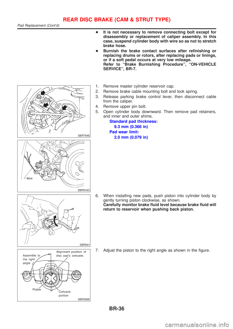
1. Remove master cylinder reservoir cap.
2. Remove brake cable mounting bolt and lock spring.
3. Release parking brake control lever, then disconnect cable
from the caliper.
4. Remove upper pin bolt.
5. Open cylinder body downward. Then remove pad retainers,
and inner and outer shims.
Standard pad thickness:
9.3 mm (0.366 in)
Pad wear limit:
2.0 mm (0.079 in)
SBR641
6. When installing new pads, push piston into cylinder body by
gently turning piston clockwise, as shown.
Carefully monitor brake fluid level because brake fluid will
return to reservoir when pushing back piston.
SBR306E
7. Adjust the piston to the right angle as shown in the figure.
REAR DISC BRAKE (CAM & STRUT TYPE)
Pad Replacement (Cont'd)
BR-36
Page 1735 of 2493

SBR307E
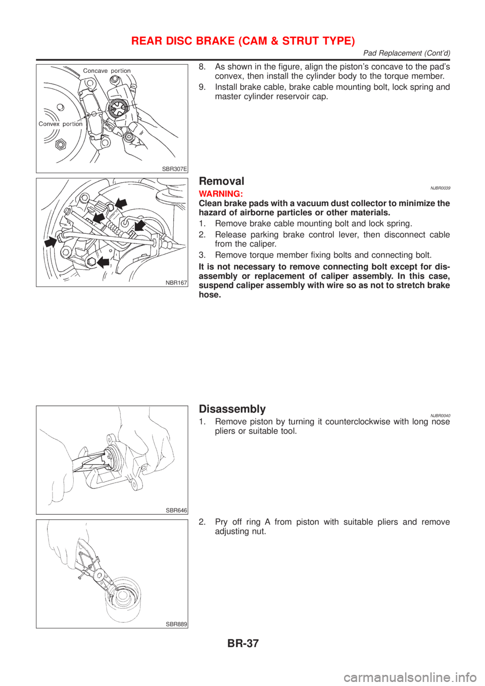
8. As shown in the figure, align the piston's concave to the pad's
convex, then install the cylinder body to the torque member.
9. Install brake cable, brake cable mounting bolt, lock spring and
master cylinder reservoir cap.
NBR167
RemovalNJBR0039WARNING:
Clean brake pads with a vacuum dust collector to minimize the
hazard of airborne particles or other materials.
1. Remove brake cable mounting bolt and lock spring.
2. Release parking brake control lever, then disconnect cable
from the caliper.
3. Remove torque member fixing bolts and connecting bolt.
It is not necessary to remove connecting bolt except for dis-
assembly or replacement of caliper assembly. In this case,
suspend caliper assembly with wire so as not to stretch brake
hose.
SBR646
DisassemblyNJBR00401. Remove piston by turning it counterclockwise with long nose
pliers or suitable tool.
SBR889
2. Pry off ring A from piston with suitable pliers and remove
adjusting nut.
REAR DISC BRAKE (CAM & STRUT TYPE)
Pad Replacement (Cont'd)
BR-37
Page 1739 of 2493
SBR892
6. Install cup in the specified direction.
SBR755E
7. Install adjuster, bearing, washers and ring A with a suitable
tool.
SBR646
8. Insert piston seal into groove on cylinder body.
9. With piston boot fitted to piston, insert piston boot into groove
on cylinder body and fit piston by turning it clockwise with long
nose pilers, or suitable tool.
SBR767E
10. Fit toggle lever, return spring and cable guide.
SBR306E
11. Adjust the piston to the right angle as shown in the figure.
REAR DISC BRAKE (CAM & STRUT TYPE)
Assembly (Cont'd)
BR-41
Page 1742 of 2493
NBR423
1. Remove master cylinder reservoir cap.
2. Remove brake cable lock spring.
3. Release parking brake control lever, then disconnect cable
from the caliper.
4. Remove upper pin bolt.
NBR426
5. Open cylinder body downward. Then remove pads inner and
outer shims.
Standard pad thickness:
9.3 mm (0.366 in)
Pad wear limit:
2.0 mm (0.079 in)
SBR641
6. When installing new pads, push piston into cylinder body by
gently turning piston clockwise, as shown.
Carefully monitor brake fluid level because brake fluid will
return to reservoir when pushing back piston.
NBR374
7. Adjust the piston to the right angle as shown in the figure.
NBR375
8. As shown in the figure, align the piston's concave to the pad's
convex, then install the cylinder body to the torque member.
9. Install brake cable, brake cable mounting bolt, lock spring and
master cylinder reservoir cap.
REAR DISC BRAKE (BALL & RAMP TYPE)
Pad Replacement (Cont'd)
BR-44
Page 1979 of 2493

RHA273D
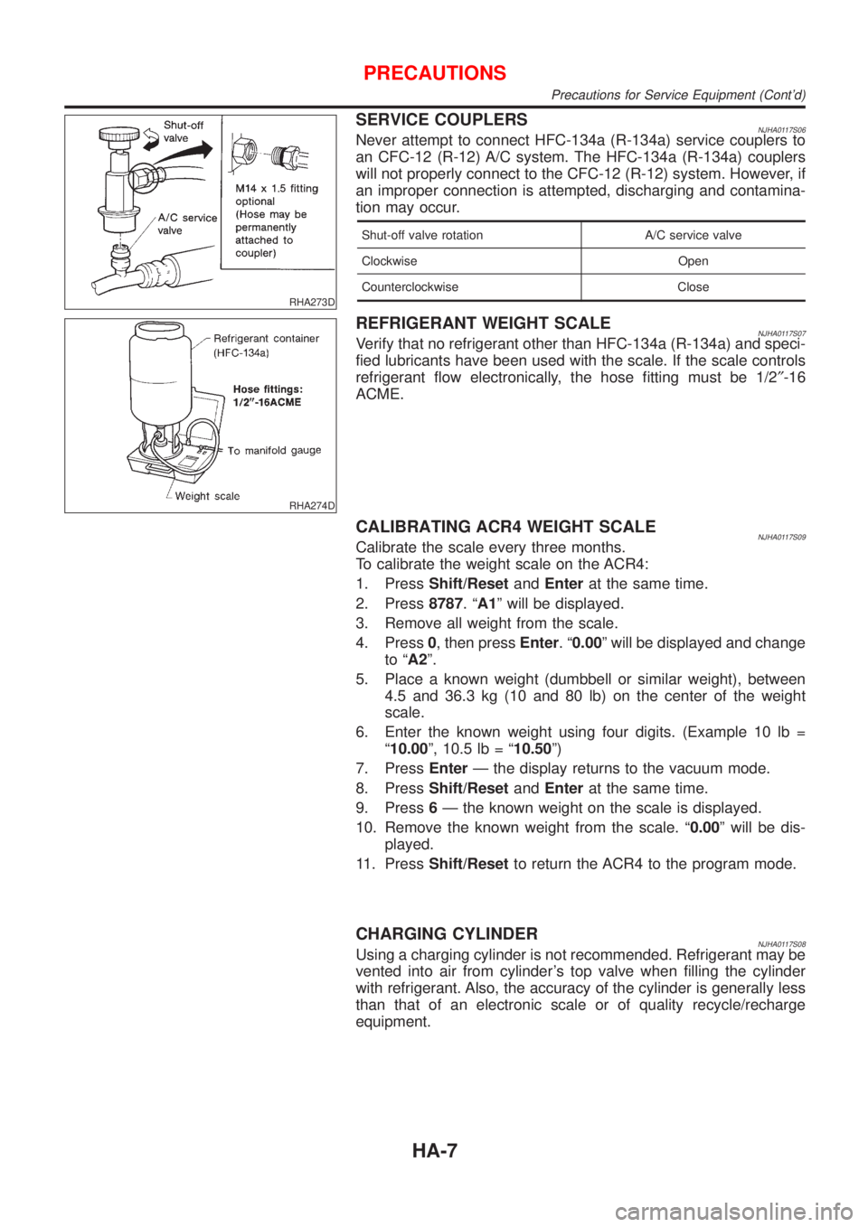
SERVICE COUPLERSNJHA0117S06Never attempt to connect HFC-134a (R-134a) service couplers to
an CFC-12 (R-12) A/C system. The HFC-134a (R-134a) couplers
will not properly connect to the CFC-12 (R-12) system. However, if
an improper connection is attempted, discharging and contamina-
tion may occur.
Shut-off valve rotation A/C service valve
Clockwise Open
Counterclockwise Close
RHA274D
REFRIGERANT WEIGHT SCALENJHA0117S07Verify that no refrigerant other than HFC-134a (R-134a) and speci-
fied lubricants have been used with the scale. If the scale controls
refrigerant flow electronically, the hose fitting must be 1/2²-16
ACME.
CALIBRATING ACR4 WEIGHT SCALENJHA0117S09Calibrate the scale every three months.
To calibrate the weight scale on the ACR4:
1. PressShift/ResetandEnterat the same time.
2. Press8787.ªA1º will be displayed.
3. Remove all weight from the scale.
4. Press0, then pressEnter.ª0.00º will be displayed and change
to ªA2º.
5. Place a known weight (dumbbell or similar weight), between
4.5 and 36.3 kg (10 and 80 lb) on the center of the weight
scale.
6. Enter the known weight using four digits. (Example 10 lb =
ª10.00º, 10.5 lb = ª10.50º)
7. PressEnterÐ the display returns to the vacuum mode.
8. PressShift/ResetandEnterat the same time.
9. Press6Ð the known weight on the scale is displayed.
10. Remove the known weight from the scale. ª0.00º will be dis-
played.
11. PressShift/Resetto return the ACR4 to the program mode.
CHARGING CYLINDERNJHA0117S08Using a charging cylinder is not recommended. Refrigerant may be
vented into air from cylinder's top valve when filling the cylinder
with refrigerant. Also, the accuracy of the cylinder is generally less
than that of an electronic scale or of quality recycle/recharge
equipment.
PRECAUTIONS
Precautions for Service Equipment (Cont'd)
HA-7
Page 2063 of 2493
RHA136E
REMOVALNJHA0212+When removing center bolt, hold clutch disc with clutch disc
wrench.
RHA399FA
RHA124FA
+Remove the clutch disc using the clutch disc puller.
Insert the holder's three pins into the holes in the clutch disc.
Rotate the holder clockwise to hook it onto the plate. Then,
tighten the center bolt to remove the clutch disc.
After removing the clutch disc, remove the shims from either
the drive shaft or the clutch disc.
RHA138E
+Remove the snap ring using external snap ring pliers.
RHA139E
+Pulley removal
Position the center pulley puller on the end of the drive shaft,
and remove the pulley assembly using any commercially avail-
able pulley puller.
To prevent the pulley groove from being deformed, the
puller claws should be positioned onto the edge of the
pulley assembly.
SERVICE PROCEDURE
Compressor Clutch Ð CSV613 (CALSONIC make) (Cont'd)
HA-91