Page 1405 of 2493
Diagnostic ProcedureNJAT0289
1 CHECK SHIFT SOLENOID VALVE
1. Remove control valve assembly. Refer to AT-343.
2. Check shift solenoid valve operation.
+Shift solenoid valve A
Refer to ªComponent Inspectionº below.
SAT886JA
OK or NG
OK©GO TO 2.
NG©Repair or replace shift solenoid valve assembly.
2 CHECK CONTROL VALVE
1. Disassemble control valve assembly. Refer to ªControl Valve Assemblyº, AT-375.
2. Check to ensure that:
+Valve, sleeve and plug slide along valve bore under their own weight.
+Valve, sleeve and plug are free from burrs, dents and scratches.
+Control valve springs are free from damage, deformation and fatigue.
+Hydraulic line is free from obstacles.
SAT367H
OK or NG
OK©GO TO 3.
NG©Repair control valve assembly.
DTC P0733 A/T 3RD GEAR FUNCTIONEURO-OBD
Diagnostic Procedure
AT-219
Page 1413 of 2493
3 CHECK SOLENOID VALVES
1. Remove control valve assembly.
Refer to AT-343.
2. Refer to ªComponent Inspectionº, AT-230.
SAT847JB
OK or NG
OK©GO TO 4.
NG©Replace solenoid valve assembly.
4 CHECK CONTROL VALVE
1. Disassemble control valve assembly.
Refer to AT-375.
2. Check to ensure that:
+Valve, sleeve and plug slide along valve bore under their own weight.
+Valve, sleeve and plug are free from burrs, dents and scratches.
+Control valve springs are free from damage, deformation and fatigue.
+Hydraulic line is free from obstacles.
SAT367H
OK or NG
OK©GO TO 5.
NG©Repair control valve.
DTC P0734 A/T 4TH GEAR FUNCTIONEURO-OBD
Diagnostic Procedure (Cont'd)
AT-227
Page 1684 of 2493

SFA449BB
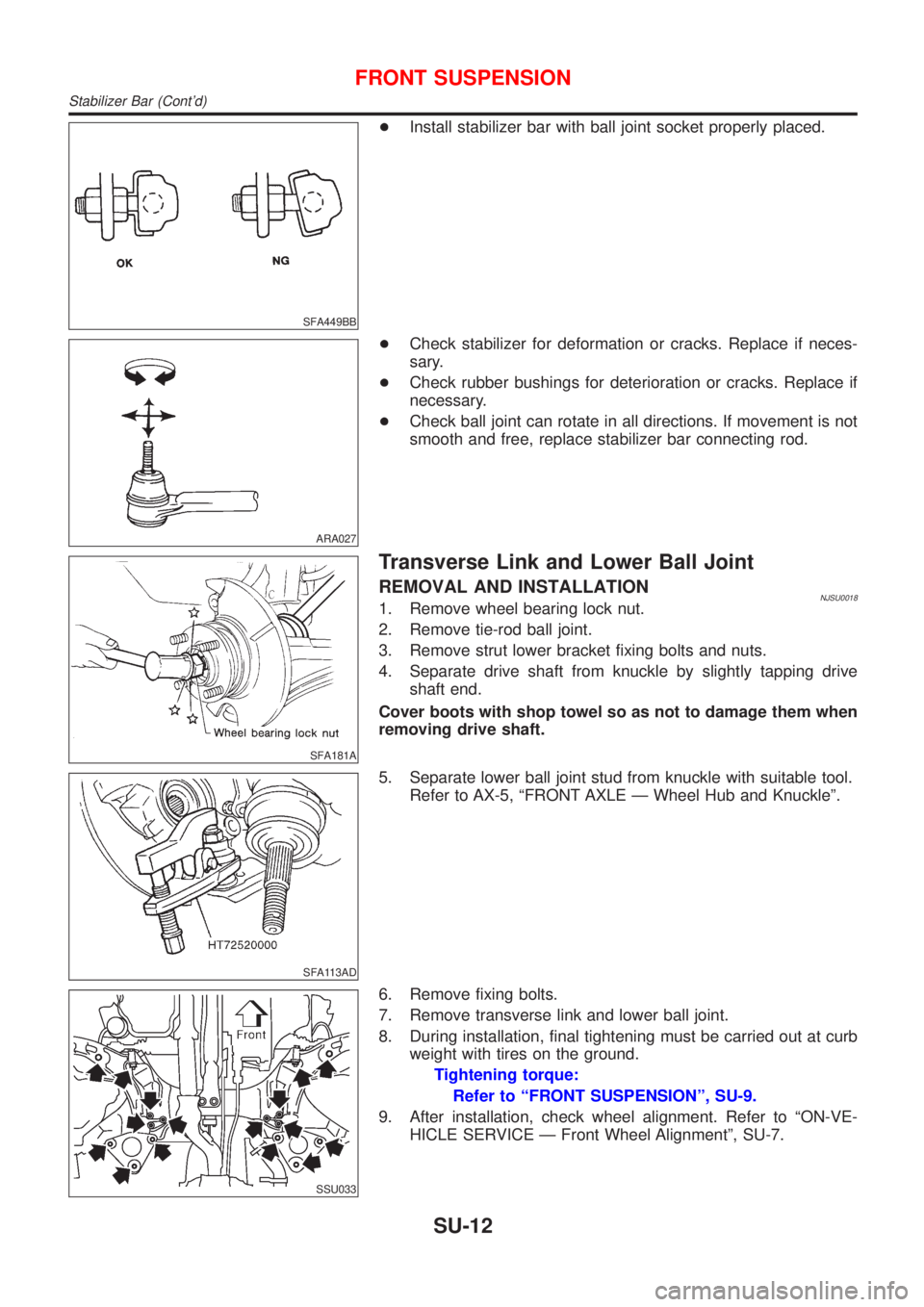
+Install stabilizer bar with ball joint socket properly placed.
ARA027
+Check stabilizer for deformation or cracks. Replace if neces-
sary.
+Check rubber bushings for deterioration or cracks. Replace if
necessary.
+Check ball joint can rotate in all directions. If movement is not
smooth and free, replace stabilizer bar connecting rod.
SFA181A
Transverse Link and Lower Ball Joint
REMOVAL AND INSTALLATIONNJSU00181. Remove wheel bearing lock nut.
2. Remove tie-rod ball joint.
3. Remove strut lower bracket fixing bolts and nuts.
4. Separate drive shaft from knuckle by slightly tapping drive
shaft end.
Cover boots with shop towel so as not to damage them when
removing drive shaft.
SFA113AD
5. Separate lower ball joint stud from knuckle with suitable tool.
Refer to AX-5, ªFRONT AXLE Ð Wheel Hub and Knuckleº.
SSU033
6. Remove fixing bolts.
7. Remove transverse link and lower ball joint.
8. During installation, final tightening must be carried out at curb
weight with tires on the ground.
Tightening torque:
Refer to ªFRONT SUSPENSIONº, SU-9.
9. After installation, check wheel alignment. Refer to ªON-VE-
HICLE SERVICE Ð Front Wheel Alignmentº, SU-7.
FRONT SUSPENSION
Stabilizer Bar (Cont'd)
SU-12
Page 1979 of 2493

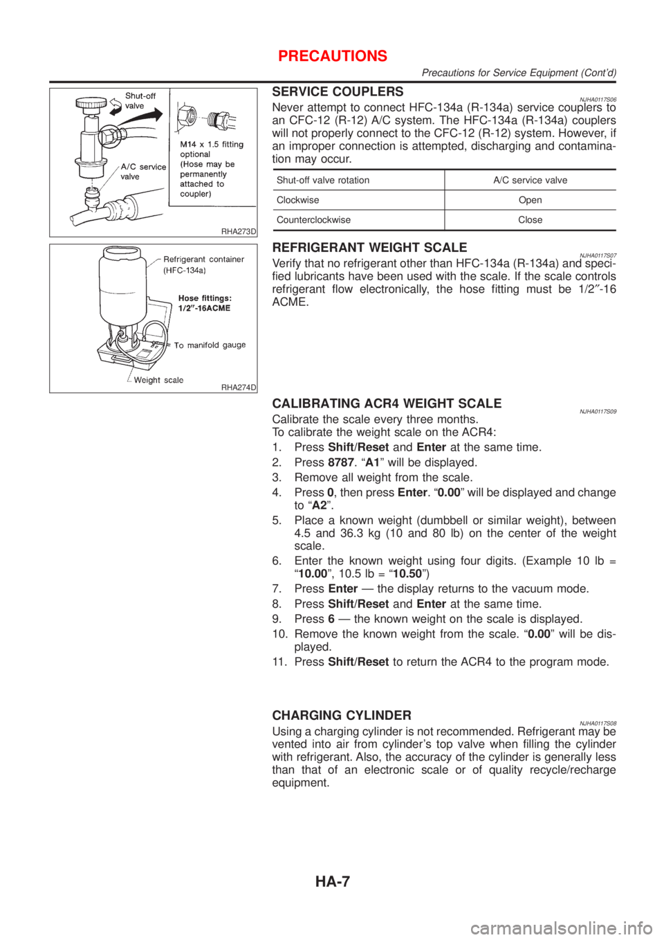
RHA273D
SERVICE COUPLERSNJHA0117S06Never attempt to connect HFC-134a (R-134a) service couplers to
an CFC-12 (R-12) A/C system. The HFC-134a (R-134a) couplers
will not properly connect to the CFC-12 (R-12) system. However, if
an improper connection is attempted, discharging and contamina-
tion may occur.
Shut-off valve rotation A/C service valve
Clockwise Open
Counterclockwise Close
RHA274D
REFRIGERANT WEIGHT SCALENJHA0117S07Verify that no refrigerant other than HFC-134a (R-134a) and speci-
fied lubricants have been used with the scale. If the scale controls
refrigerant flow electronically, the hose fitting must be 1/2²-16
ACME.
CALIBRATING ACR4 WEIGHT SCALENJHA0117S09Calibrate the scale every three months.
To calibrate the weight scale on the ACR4:
1. PressShift/ResetandEnterat the same time.
2. Press8787.ªA1º will be displayed.
3. Remove all weight from the scale.
4. Press0, then pressEnter.ª0.00º will be displayed and change
to ªA2º.
5. Place a known weight (dumbbell or similar weight), between
4.5 and 36.3 kg (10 and 80 lb) on the center of the weight
scale.
6. Enter the known weight using four digits. (Example 10 lb =
ª10.00º, 10.5 lb = ª10.50º)
7. PressEnterÐ the display returns to the vacuum mode.
8. PressShift/ResetandEnterat the same time.
9. Press6Ð the known weight on the scale is displayed.
10. Remove the known weight from the scale. ª0.00º will be dis-
played.
11. PressShift/Resetto return the ACR4 to the program mode.
CHARGING CYLINDERNJHA0117S08Using a charging cylinder is not recommended. Refrigerant may be
vented into air from cylinder's top valve when filling the cylinder
with refrigerant. Also, the accuracy of the cylinder is generally less
than that of an electronic scale or of quality recycle/recharge
equipment.
PRECAUTIONS
Precautions for Service Equipment (Cont'd)
HA-7
Page 1984 of 2493
Tool number
Tool nameDescription
Service hoses
+High side hose
+Low side hose
+Utility hose
NT201
Hose color:
+Low hose: Blue with black stripe
+High hose: Red with black stripe
+Utility hose: Yellow with black stripe or green
with black stripe
Hose fitting to gauge:
+1/2²-16 ACME
Service couplers
+High side coupler
+Low side coupler
NT202
Hose fitting to service hose:
+M14 x 1.5 fitting is optional or permanently
attached.
Refrigerant weight scale
NT200
For measuring of refrigerant
Fitting size: Thread size
+1/2²-16 ACME
Vacuum pump
(Including the isolator
valve)
NT203
Capacity:
+Air displacement: 4 CFM
+Micron rating: 20 microns
+Oil capacity: 482 g (17 oz)
Fitting size: Thread size
+1/2²-16 ACME
PREPARATION
HFC-134a (R-134a) Service Tools and Equipment (Cont'd)
HA-12
Page 2154 of 2493

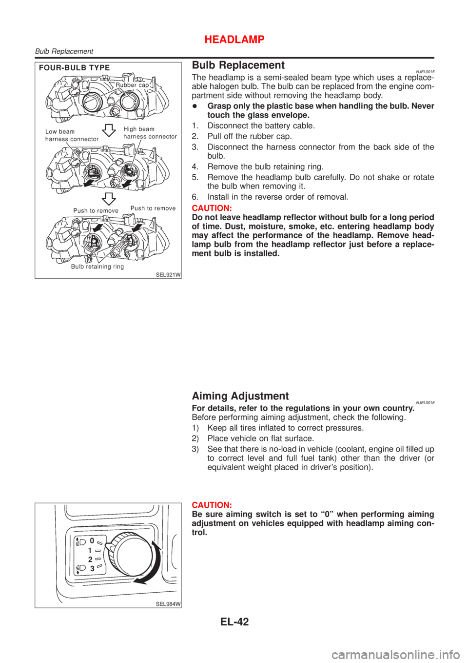
SEL921W
Bulb ReplacementNJEL0015The headlamp is a semi-sealed beam type which uses a replace-
able halogen bulb. The bulb can be replaced from the engine com-
partment side without removing the headlamp body.
+Grasp only the plastic base when handling the bulb. Never
touch the glass envelope.
1. Disconnect the battery cable.
2. Pull off the rubber cap.
3. Disconnect the harness connector from the back side of the
bulb.
4. Remove the bulb retaining ring.
5. Remove the headlamp bulb carefully. Do not shake or rotate
the bulb when removing it.
6. Install in the reverse order of removal.
CAUTION:
Do not leave headlamp reflector without bulb for a long period
of time. Dust, moisture, smoke, etc. entering headlamp body
may affect the performance of the headlamp. Remove head-
lamp bulb from the headlamp reflector just before a replace-
ment bulb is installed.
Aiming AdjustmentNJEL0016For details, refer to the regulations in your own country.
Before performing aiming adjustment, check the following.
1) Keep all tires inflated to correct pressures.
2) Place vehicle on flat surface.
3) See that there is no-load in vehicle (coolant, engine oil filled up
to correct level and full fuel tank) other than the driver (or
equivalent weight placed in driver's position).
SEL984W
CAUTION:
Be sure aiming switch is set to ª0º when performing aiming
adjustment on vehicles equipped with headlamp aiming con-
trol.
HEADLAMP
Bulb Replacement
EL-42
Page 2174 of 2493

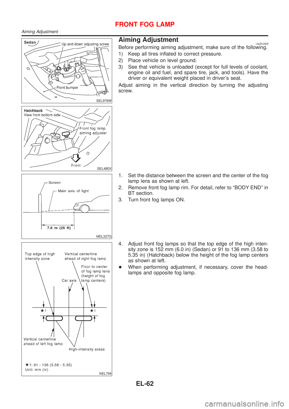
SEL976W
SEL480X
Aiming Adjustment=NJEL0029Before performing aiming adjustment, make sure of the following.
1) Keep all tires inflated to correct pressure.
2) Place vehicle on level ground.
3) See that vehicle is unloaded (except for full levels of coolant,
engine oil and fuel, and spare tire, jack, and tools). Have the
driver or equivalent weight placed in driver's seat.
Adjust aiming in the vertical direction by turning the adjusting
screw.
MEL327G
1. Set the distance between the screen and the center of the fog
lamp lens as shown at left.
2. Remove front fog lamp rim. For detail, refer to ªBODY ENDº in
BT section.
3. Turn front fog lamps ON.
NEL794
4. Adjust front fog lamps so that the top edge of the high inten-
sity zone is 152 mm (6.0 in) (Sedan) or 91 to 136 mm (3.58 to
5.35 in) (Hatchback) below the height of the fog lamp centers
as shown at left.
+When performing adjustment, if necessary, cover the head-
lamps and opposite fog lamp.
FRONT FOG LAMP
Aiming Adjustment
EL-62