2001 NISSAN ALMERA N16 light adjustment
[x] Cancel search: light adjustmentPage 2114 of 2493

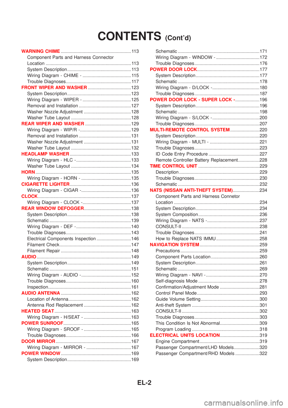
WARNING CHIME....................................................... 113
Component Parts and Harness Connector
Location ................................................................... 113
System Description .................................................. 113
Wiring Diagram - CHIME - ...................................... 115
Trouble Diagnoses................................................... 117
FRONT WIPER AND WASHER..................................123
System Description ..................................................123
Wiring Diagram - WIPER - ......................................125
Removal and Installation .........................................127
Washer Nozzle Adjustment .....................................128
Washer Tube Layout ...............................................128
REAR WIPER AND WASHER....................................129
Wiring Diagram - WIP/R -........................................129
Removal and Installation .........................................131
Washer Nozzle Adjustment .....................................131
Washer Tube Layout ...............................................132
HEADLAMP WASHER................................................133
Wiring Diagram - HLC - ...........................................133
Washer Tube Layout ...............................................134
HORN...........................................................................135
Wiring Diagram - HORN - .......................................135
CIGARETTE LIGHTER................................................136
Wiring Diagram - CIGAR -.......................................136
CLOCK.........................................................................137
Wiring Diagram - CLOCK -......................................137
REAR WINDOW DEFOGGER.....................................138
System Description ..................................................138
Schematic ................................................................139
Wiring Diagram - DEF - ...........................................140
Trouble Diagnoses...................................................143
Electrical Components Inspection ...........................146
Filament Check ........................................................147
Filament Repair .......................................................148
AUDIO..........................................................................149
System Description ..................................................149
Schematic ................................................................151
Wiring Diagram - AUDIO - .......................................152
Trouble Diagnoses...................................................160
Inspection.................................................................161
AUDIO ANTENNA.......................................................162
Location of Antenna .................................................162
Antenna Rod Replacement .....................................162
HEATED SEAT............................................................163
Wiring Diagram - H/SEAT - .....................................163
POWER SUNROOF.....................................................165
Wiring Diagram - SROOF - .....................................165
Trouble Diagnoses...................................................166
DOOR MIRROR...........................................................167
Wiring Diagram - MIRROR - ...................................167
POWER WINDOW.......................................................169
System Description ..................................................169Schematic ................................................................171
Wiring Diagram - WINDOW - ..................................172
Trouble Diagnoses...................................................176
POWER DOOR LOCK.................................................177
System Description ..................................................177
Schematic ................................................................178
Wiring Diagram - D/LOCK -.....................................180
Trouble Diagnoses...................................................187
POWER DOOR LOCK - SUPER LOCK -...................196
System Description ..................................................196
Schematic ................................................................198
Wiring Diagram - S/LOCK - .....................................200
Trouble Diagnoses...................................................207
MULTI-REMOTE CONTROL SYSTEM.......................220
System Description ..................................................220
Wiring Diagram - MULTI - .......................................221
Trouble Diagnoses...................................................223
ID Code Entry Procedure ........................................227
Remote Controller Battery Replacement.................228
TIME CONTROL UNIT................................................229
Description ...............................................................229
Trouble Diagnoses...................................................230
Schematic ................................................................232
NATS (NISSAN ANTI-THEFT SYSTEM).....................234
Component Parts and Harness Connetor
Location ...................................................................234
System Description ..................................................234
System Composition ................................................236
Wiring Diagram - NATS -.........................................237
CONSULT-II .............................................................238
Trouble Diagnoses...................................................241
How to Replace NATS IMMU ..................................258
NAVIGATION SYSTEM...............................................259
Precautions ..............................................................259
Component Parts Location ......................................260
System Description ..................................................261
Schematic ................................................................269
Wiring Diagram - NAVI - ..........................................270
Self-diagnosis Mode ................................................278
Confirmation/Adjustment Mode ...............................281
Control Panel Mode .................................................293
Guide Volume Setting ..............................................300
Anti-theft System .....................................................301
CONSULT-II .............................................................302
Trouble Diagnoses...................................................303
This Condition Is Not Abnormal...............................309
Program Loading .....................................................318
ELECTRICAL UNITS LOCATION...............................319
Engine Compartment ...............................................319
Passenger Compartment/LHD Models ....................320
Passenger Compartment/RHD Models ...................322
CONTENTS(Cont'd)
EL-2
Page 2155 of 2493

SEL978W
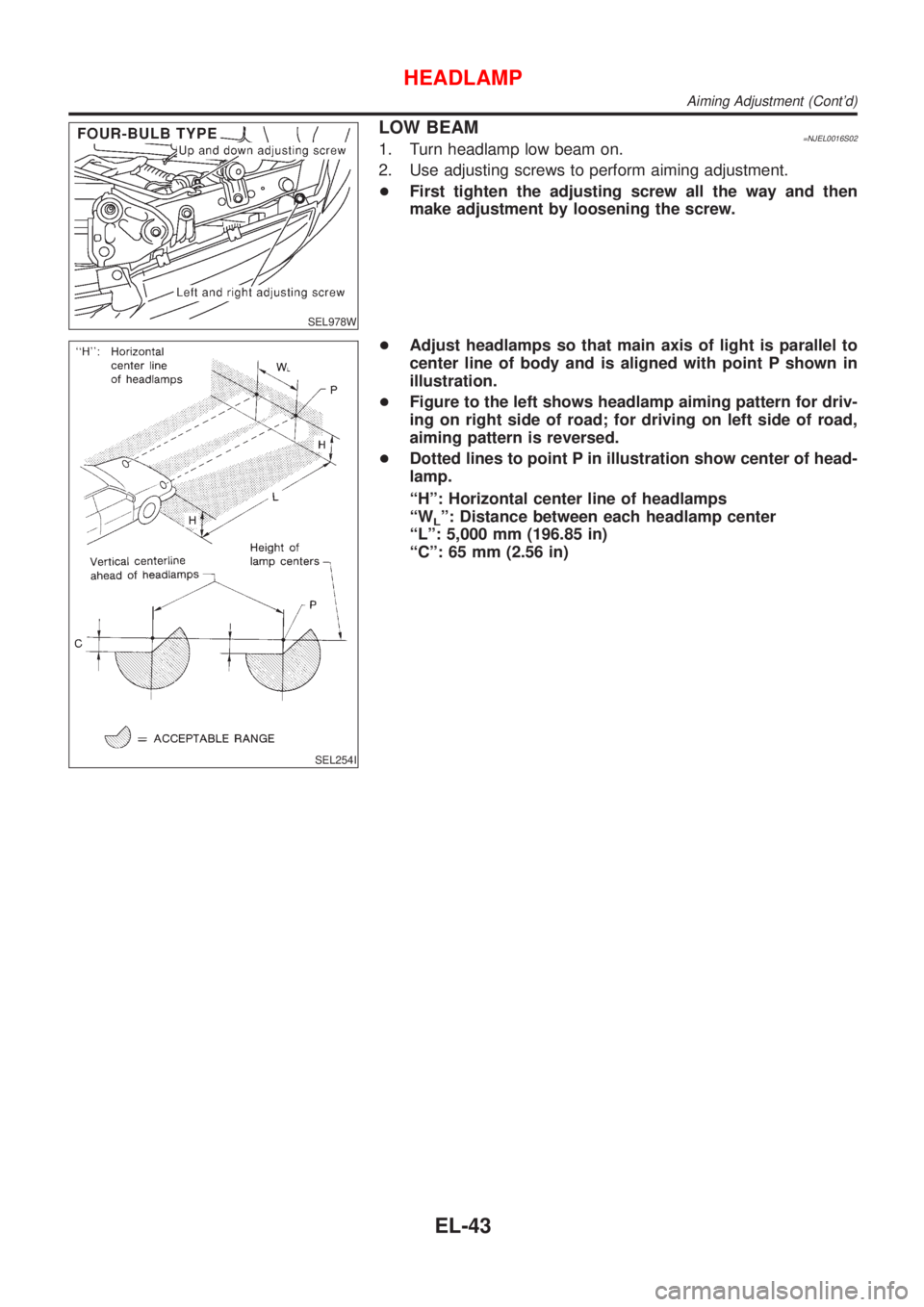
LOW BEAM=NJEL0016S021. Turn headlamp low beam on.
2. Use adjusting screws to perform aiming adjustment.
+First tighten the adjusting screw all the way and then
make adjustment by loosening the screw.
SEL254I
+Adjust headlamps so that main axis of light is parallel to
center line of body and is aligned with point P shown in
illustration.
+Figure to the left shows headlamp aiming pattern for driv-
ing on right side of road; for driving on left side of road,
aiming pattern is reversed.
+Dotted lines to point P in illustration show center of head-
lamp.
ªHº: Horizontal center line of headlamps
ªW
Lº: Distance between each headlamp center
ªLº: 5,000 mm (196.85 in)
ªCº: 65 mm (2.56 in)
HEADLAMP
Aiming Adjustment (Cont'd)
EL-43
Page 2162 of 2493

Aiming AdjustmentNJEL0356Refer to ªHEADLAMPº (EL-42).
HEADLAMP Ð DAYTIME LIGHT SYSTEM Ð
Aiming Adjustment
EL-50
Page 2397 of 2493

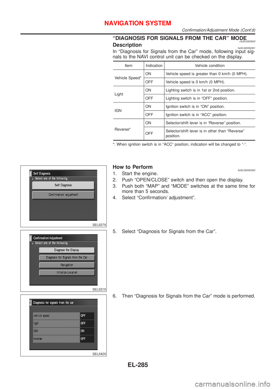
ªDIAGNOSIS FOR SIGNALS FROM THE CARº MODE=NJEL0520S03DescriptionNJEL0520S0301In ªDiagnosis for Signals from the Carº mode, following input sig-
nals to the NAVI control unit can be checked on the display.
Item Indication Vehicle condition
Vehicle Speed*ON Vehicle speed is greater than 0 km/h (0 MPH).
OFF Vehicle speed is 0 km/h (0 MPH).
LightON Lighting switch is in 1st or 2nd position.
OFF Lighting switch is in ªOFFº position.
IGNON Ignition switch is in ªONº position.
OFF Ignition switch is in ªACCº position.
Reverse*ON Selector/shift lever is in ªReverseº position.
OFFSelector/shift lever is in other than ªReverseº
position.
*: When ignition switch is in ªACCº position, indication will be changed to ª-º.
SEL527X
How to PerformNJEL0520S03021. Start the engine.
2. Push ªOPEN/CLOSEº switch and then open the display.
3. Push both ªMAPº and ªMODEº switches at the same time for
more than 5 seconds.
4. Select ªConfirmation/ adjustmentº.
SEL531X
5. Select ªDiagnosis for Signals from the Carº.
SEL542X
6. Then ªDiagnosis for Signals from the Carº mode is performed.
NAVIGATION SYSTEM
Confirmation/Adjustment Mode (Cont'd)
EL-285