2001 NISSAN ALMERA N16 coolant sensor
[x] Cancel search: coolant sensorPage 171 of 2493

Secondary Timing ChainNJEM0093CAUTION:
+After removing timing chain, do not turn crankshaft and
camshaft separately, or valves will strike piston heads.
+When installing camshafts, chain tensioners, oil seals, or
other sliding parts, lubricate contacting surfaces with new
engine oil.
+Apply new engine oil to bolt threads and seat surfaces
when installing camshaft sprockets, crankshaft pulley,
and camshaft brackets.
+When removing the oil pans, oil pump assembly and tim-
ing chain from engine, first remove the crankshaft posi-
tion sensor (TDC sensor).
Be careful not to damage sensor edges.
+Do not spill engine coolant on drive belts.
JEM120G
REMOVALNJEM0093S01+For preparative work for removing/installing secondary timing
chain to remove/install fuel injection pump, refer to EC-513,
ªElectronic control fuel injection pumpº.
+To prepare for removing/installing secondary timing chain to
remove/install camshaft, refer to EM-119, ªCAMSHAFTº.
1. Drain engine oil.
2. Drain coolant by removing cylinder block drain plugs. Refer to
LC-43, ªChanging Engine Coolantº.
TIMING CHAINYD
Secondary Timing Chain
EM-93
Page 215 of 2493

crankshaft position sensor (TDC sensor) from the assem-
bly.
+Always pay extra attention not to damage edge of crank-
shaft position sensor (TDC sensor) or ring gear teeth.
REMOVALNJEM0069S011. Remove engine undercover, and hood for hoisting.
2. Drain coolant from both cylinder block and radiator. Refer to
LC-43, ªChanging Engine Coolantº.
3. Remove the following parts:
+Battery
+RH and LH front wheels
+RH and LH splash covers (combined with undercover)
+Auxiliary belts
+Alternator
+Alternator brackets
+Radiator and cooling fan
+Engine cover
+Air ducts and air cleaner case
LH side of engine room:
4. Disconnect all harnesses and grounds that are connected to
components on vehicle.
5. Disconnect vacuum hose on vacuum pump side.
6. Disconnect fuel feed and fuel return hoses on engine side.
+Immediately put blind plugs into the openings to prevent
fuel from flowing out.
7. Disconnect heater hose. Plug opening of hose to prevent cool-
ant from flowing out.
RH side of engine room:
8. Remove air conditioner compressor from brackets and move
it toward vehicle side. Secure compressor on vehicle side with
rope.
Vehicle underside:
9. Remove exhaust front tube.
10. Disconnect two hoses from power steering pump and plug to
stop fluid.
11. Remove M/T control rod and support rod.
12. Remove ABS wheel sensor, and temporarily hang brake cali-
per with rope on vehicle side.
13. Remove RH and LH drive shafts.
YEM024
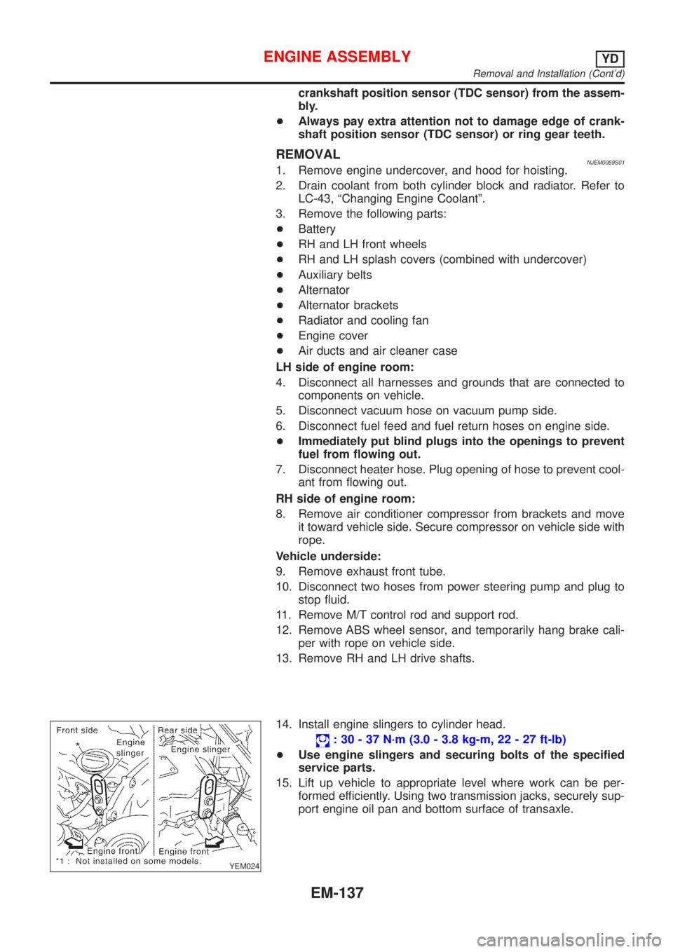
14. Install engine slingers to cylinder head.
: 30 - 37 N´m (3.0 - 3.8 kg-m, 22 - 27 ft-lb)
+Use engine slingers and securing bolts of the specified
service parts.
15. Lift up vehicle to appropriate level where work can be per-
formed efficiently. Using two transmission jacks, securely sup-
port engine oil pan and bottom surface of transaxle.
ENGINE ASSEMBLYYD
Removal and Installation (Cont'd)
EM-137
Page 298 of 2493

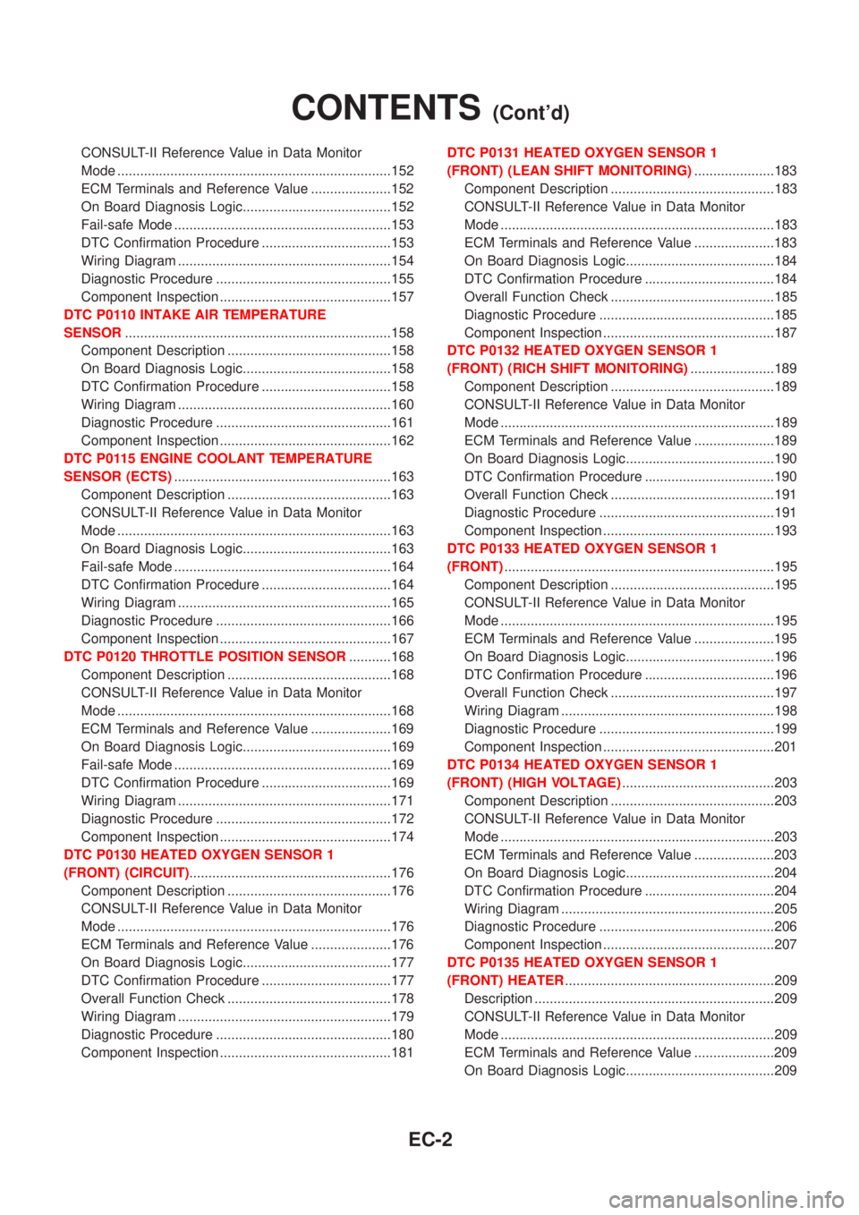
CONSULT-II Reference Value in Data Monitor
Mode ........................................................................152
ECM Terminals and Reference Value .....................152
On Board Diagnosis Logic.......................................152
Fail-safe Mode .........................................................153
DTC Confirmation Procedure ..................................153
Wiring Diagram ........................................................154
Diagnostic Procedure ..............................................155
Component Inspection .............................................157
DTC P0110 INTAKE AIR TEMPERATURE
SENSOR......................................................................158
Component Description ...........................................158
On Board Diagnosis Logic.......................................158
DTC Confirmation Procedure ..................................158
Wiring Diagram ........................................................160
Diagnostic Procedure ..............................................161
Component Inspection .............................................162
DTC P0115 ENGINE COOLANT TEMPERATURE
SENSOR (ECTS).........................................................163
Component Description ...........................................163
CONSULT-II Reference Value in Data Monitor
Mode ........................................................................163
On Board Diagnosis Logic.......................................163
Fail-safe Mode .........................................................164
DTC Confirmation Procedure ..................................164
Wiring Diagram ........................................................165
Diagnostic Procedure ..............................................166
Component Inspection .............................................167
DTC P0120 THROTTLE POSITION SENSOR...........168
Component Description ...........................................168
CONSULT-II Reference Value in Data Monitor
Mode ........................................................................168
ECM Terminals and Reference Value .....................169
On Board Diagnosis Logic.......................................169
Fail-safe Mode .........................................................169
DTC Confirmation Procedure ..................................169
Wiring Diagram ........................................................171
Diagnostic Procedure ..............................................172
Component Inspection .............................................174
DTC P0130 HEATED OXYGEN SENSOR 1
(FRONT) (CIRCUIT).....................................................176
Component Description ...........................................176
CONSULT-II Reference Value in Data Monitor
Mode ........................................................................176
ECM Terminals and Reference Value .....................176
On Board Diagnosis Logic.......................................177
DTC Confirmation Procedure ..................................177
Overall Function Check ...........................................178
Wiring Diagram ........................................................179
Diagnostic Procedure ..............................................180
Component Inspection .............................................181DTC P0131 HEATED OXYGEN SENSOR 1
(FRONT) (LEAN SHIFT MONITORING).....................183
Component Description ...........................................183
CONSULT-II Reference Value in Data Monitor
Mode ........................................................................183
ECM Terminals and Reference Value .....................183
On Board Diagnosis Logic.......................................184
DTC Confirmation Procedure ..................................184
Overall Function Check ...........................................185
Diagnostic Procedure ..............................................185
Component Inspection .............................................187
DTC P0132 HEATED OXYGEN SENSOR 1
(FRONT) (RICH SHIFT MONITORING)......................189
Component Description ...........................................189
CONSULT-II Reference Value in Data Monitor
Mode ........................................................................189
ECM Terminals and Reference Value .....................189
On Board Diagnosis Logic.......................................190
DTC Confirmation Procedure ..................................190
Overall Function Check ...........................................191
Diagnostic Procedure ..............................................191
Component Inspection .............................................193
DTC P0133 HEATED OXYGEN SENSOR 1
(FRONT).......................................................................195
Component Description ...........................................195
CONSULT-II Reference Value in Data Monitor
Mode ........................................................................195
ECM Terminals and Reference Value .....................195
On Board Diagnosis Logic.......................................196
DTC Confirmation Procedure ..................................196
Overall Function Check ...........................................197
Wiring Diagram ........................................................198
Diagnostic Procedure ..............................................199
Component Inspection .............................................201
DTC P0134 HEATED OXYGEN SENSOR 1
(FRONT) (HIGH VOLTAGE)........................................203
Component Description ...........................................203
CONSULT-II Reference Value in Data Monitor
Mode ........................................................................203
ECM Terminals and Reference Value .....................203
On Board Diagnosis Logic.......................................204
DTC Confirmation Procedure ..................................204
Wiring Diagram ........................................................205
Diagnostic Procedure ..............................................206
Component Inspection .............................................207
DTC P0135 HEATED OXYGEN SENSOR 1
(FRONT) HEATER.......................................................209
Description ...............................................................209
CONSULT-II Reference Value in Data Monitor
Mode ........................................................................209
ECM Terminals and Reference Value .....................209
On Board Diagnosis Logic.......................................209
CONTENTS(Cont'd)
EC-2
Page 302 of 2493

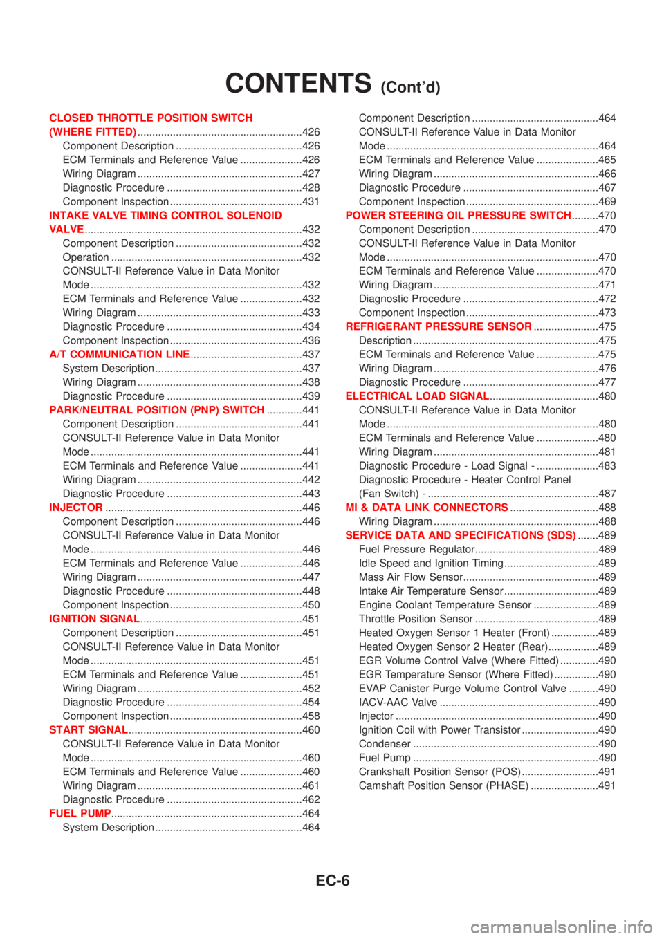
CLOSED THROTTLE POSITION SWITCH
(WHERE FITTED)........................................................426
Component Description ...........................................426
ECM Terminals and Reference Value .....................426
Wiring Diagram ........................................................427
Diagnostic Procedure ..............................................428
Component Inspection .............................................431
INTAKE VALVE TIMING CONTROL SOLENOID
VALVE..........................................................................432
Component Description ...........................................432
Operation .................................................................432
CONSULT-II Reference Value in Data Monitor
Mode ........................................................................432
ECM Terminals and Reference Value .....................432
Wiring Diagram ........................................................433
Diagnostic Procedure ..............................................434
Component Inspection .............................................436
A/T COMMUNICATION LINE......................................437
System Description ..................................................437
Wiring Diagram ........................................................438
Diagnostic Procedure ..............................................439
PARK/NEUTRAL POSITION (PNP) SWITCH............441
Component Description ...........................................441
CONSULT-II Reference Value in Data Monitor
Mode ........................................................................441
ECM Terminals and Reference Value .....................441
Wiring Diagram ........................................................442
Diagnostic Procedure ..............................................443
INJECTOR...................................................................446
Component Description ...........................................446
CONSULT-II Reference Value in Data Monitor
Mode ........................................................................446
ECM Terminals and Reference Value .....................446
Wiring Diagram ........................................................447
Diagnostic Procedure ..............................................448
Component Inspection .............................................450
IGNITION SIGNAL.......................................................451
Component Description ...........................................451
CONSULT-II Reference Value in Data Monitor
Mode ........................................................................451
ECM Terminals and Reference Value .....................451
Wiring Diagram ........................................................452
Diagnostic Procedure ..............................................454
Component Inspection .............................................458
START SIGNAL...........................................................460
CONSULT-II Reference Value in Data Monitor
Mode ........................................................................460
ECM Terminals and Reference Value .....................460
Wiring Diagram ........................................................461
Diagnostic Procedure ..............................................462
FUEL PUMP.................................................................464
System Description ..................................................464Component Description ...........................................464
CONSULT-II Reference Value in Data Monitor
Mode ........................................................................464
ECM Terminals and Reference Value .....................465
Wiring Diagram ........................................................466
Diagnostic Procedure ..............................................467
Component Inspection .............................................469
POWER STEERING OIL PRESSURE SWITCH.........470
Component Description ...........................................470
CONSULT-II Reference Value in Data Monitor
Mode ........................................................................470
ECM Terminals and Reference Value .....................470
Wiring Diagram ........................................................471
Diagnostic Procedure ..............................................472
Component Inspection .............................................473
REFRIGERANT PRESSURE SENSOR......................475
Description ...............................................................475
ECM Terminals and Reference Value .....................475
Wiring Diagram ........................................................476
Diagnostic Procedure ..............................................477
ELECTRICAL LOAD SIGNAL.....................................480
CONSULT-II Reference Value in Data Monitor
Mode ........................................................................480
ECM Terminals and Reference Value .....................480
Wiring Diagram ........................................................481
Diagnostic Procedure - Load Signal - .....................483
Diagnostic Procedure - Heater Control Panel
(Fan Switch) - ..........................................................487
MI & DATA LINK CONNECTORS..............................488
Wiring Diagram ........................................................488
SERVICE DATA AND SPECIFICATIONS (SDS).......489
Fuel Pressure Regulator..........................................489
Idle Speed and Ignition Timing ................................489
Mass Air Flow Sensor..............................................489
Intake Air Temperature Sensor ................................489
Engine Coolant Temperature Sensor ......................489
Throttle Position Sensor ..........................................489
Heated Oxygen Sensor 1 Heater (Front) ................489
Heated Oxygen Sensor 2 Heater (Rear).................489
EGR Volume Control Valve (Where Fitted) .............490
EGR Temperature Sensor (Where Fitted) ...............490
EVAP Canister Purge Volume Control Valve ..........490
IACV-AAC Valve ......................................................490
Injector .....................................................................490
Ignition Coil with Power Transistor ..........................490
Condenser ...............................................................490
Fuel Pump ...............................................................490
Crankshaft Position Sensor (POS) ..........................491
Camshaft Position Sensor (PHASE) .......................491
CONTENTS(Cont'd)
EC-6
Page 303 of 2493

YD
TROUBLE DIAGNOSIS - INDEX................................492
Alphabetical & P No. Index for DTC .......................492
PRECAUTIONS...........................................................494
Supplemental Restraint System (SRS)²AIR
BAG²and²SEAT BELT PRE-TENSIONER²...........494
Engine Fuel & Emission Control System ................495
Precautions ..............................................................496
Wiring Diagrams and Trouble Diagnosis .................497
PREPARATION...........................................................498
Special Service Tools ..............................................498
ENGINE AND EMISSION CONTROL OVERALL
SYSTEM.......................................................................499
Engine Control Component Parts Location .............499
Circuit Diagram ........................................................502
System Diagram ......................................................503
System Chart ...........................................................504
ENGINE AND EMISSION BASIC CONTROL
SYSTEM DESCRIPTION.............................................505
Fuel Injection Control System .................................505
Fuel Injection Timing Control System......................506
Air Conditioning Cut Control ....................................507
Fuel Cut Control (at no load & high engine
speed) ......................................................................507
Crankcase Ventilation System .................................508
BASIC SERVICE PROCEDURE.................................509
Injection Tube and Injection Nozzle ........................509
Electronic Control Fuel Injection Pump ...................513
Fuel Filter .................................................................520
ON BOARD DIAGNOSTIC SYSTEM
DESCRIPTION.............................................................522
DTC and MI Detection Logic ...................................522
Diagnostic Trouble Code (DTC) ..............................522
Malfunction Indicator (MI) ........................................523
CONSULT-II .............................................................527
TROUBLE DIAGNOSIS - INTRODUCTION................532
Introduction ..............................................................532
Work Flow ................................................................534
TROUBLE DIAGNOSIS - BASIC INSPECTION.........536
Basic Inspection.......................................................536
TROUBLE DIAGNOSIS - GENERAL
DESCRIPTION.............................................................541
Symptom Matrix Chart .............................................541
CONSULT-II Reference Value in Data Monitor
Mode ........................................................................551
Major Sensor Reference Graph in Data Monitor
Mode ........................................................................553
ECM Terminals and Reference Value .....................554
TROUBLE DIAGNOSIS FOR INTERMITTENT
INCIDENT.....................................................................559
Description ...............................................................559
Diagnostic Procedure ..............................................559TROUBLE DIAGNOSIS FOR POWER SUPPLY........560
Main Power Supply and Ground Circuit ..................560
DTC P0100 MASS AIR FLOW SEN...........................566
Component Description ...........................................566
CONSULT-II Reference Value in Data Monitor
Mode ........................................................................566
ECM Terminals and Reference Value .....................566
On Board Diagnosis Logic.......................................566
DTC Confirmation Procedure ..................................566
Wiring Diagram ........................................................568
Diagnostic Procedure ..............................................569
DTC P0115 COOLANT TEMP SEN............................572
Description ...............................................................572
On Board Diagnosis Logic.......................................572
DTC Confirmation Procedure ..................................572
Wiring Diagram ........................................................574
Diagnostic Procedure ..............................................575
DTC P0120 ACCEL POS SENSOR............................577
Description ...............................................................577
CONSULT-II Reference Value in Data Monitor
Mode ........................................................................577
ECM Terminals and Reference Value .....................577
On Board Diagnosis Logic.......................................578
DTC Confirmation Procedure ..................................578
Wiring Diagram ........................................................579
Diagnostic Procedure ..............................................580
DTC P0335 CRANK POS SEN (TDC)........................587
Description ...............................................................587
CONSULT-II Reference Value in Data Monitor
Mode ........................................................................587
ECM Terminals and Reference Value .....................587
On Board Diagnosis Logic.......................................587
DTC Confirmation Procedure ..................................588
Wiring Diagram ........................................................589
Diagnostic Procedure ..............................................590
DTC P0500 VEHICLE SPEED SEN............................593
Description ...............................................................593
ECM Terminals and Reference Value .....................593
On Board Diagnosis Logic.......................................593
Overall Function Check ...........................................593
Wiring Diagram ........................................................595
Diagnostic Procedure ..............................................596
DTC P0571 BRAKE SW..............................................597
Description ...............................................................597
ECM Terminals and Reference Value .....................597
On Board Diagnosis Logic.......................................597
DTC Confirmation Procedure ..................................597
Wiring Diagram ........................................................599
Diagnostic Procedure ..............................................600
DTC P1107 ECM 10....................................................604
Description ...............................................................604
On Board Diagnosis Logic.......................................604
CONTENTS(Cont'd)
EC-7
Page 305 of 2493

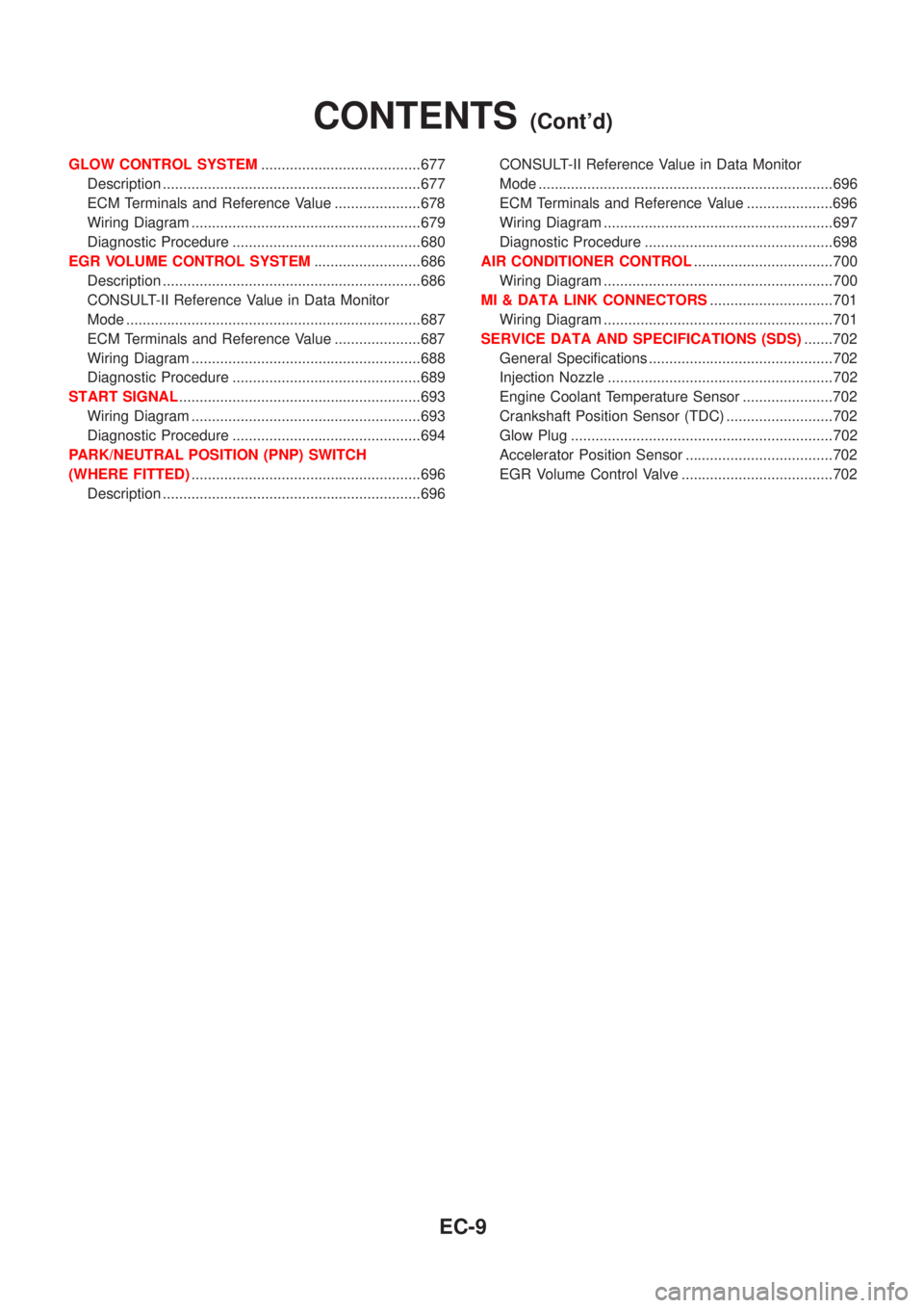
GLOW CONTROL SYSTEM.......................................677
Description ...............................................................677
ECM Terminals and Reference Value .....................678
Wiring Diagram ........................................................679
Diagnostic Procedure ..............................................680
EGR VOLUME CONTROL SYSTEM..........................686
Description ...............................................................686
CONSULT-II Reference Value in Data Monitor
Mode ........................................................................687
ECM Terminals and Reference Value .....................687
Wiring Diagram ........................................................688
Diagnostic Procedure ..............................................689
START SIGNAL...........................................................693
Wiring Diagram ........................................................693
Diagnostic Procedure ..............................................694
PARK/NEUTRAL POSITION (PNP) SWITCH
(WHERE FITTED)........................................................696
Description ...............................................................696CONSULT-II Reference Value in Data Monitor
Mode ........................................................................696
ECM Terminals and Reference Value .....................696
Wiring Diagram ........................................................697
Diagnostic Procedure ..............................................698
AIR CONDITIONER CONTROL..................................700
Wiring Diagram ........................................................700
MI & DATA LINK CONNECTORS..............................701
Wiring Diagram ........................................................701
SERVICE DATA AND SPECIFICATIONS (SDS).......702
General Specifications .............................................702
Injection Nozzle .......................................................702
Engine Coolant Temperature Sensor ......................702
Crankshaft Position Sensor (TDC) ..........................702
Glow Plug ................................................................702
Accelerator Position Sensor ....................................702
EGR Volume Control Valve .....................................702
CONTENTS(Cont'd)
EC-9
Page 310 of 2493

Items
(CONSULT-II screen terms)DTC*6
Reference page
CONSULT-II
GST*2ECM*1
COOLANT T SEN/CIRC*3 P0115 0115 EC-163
ENG OVER TEMP P1217 1217 EC-334
HO2S1 (B1) P0130 0130 EC-176
KNOCK SEN/CIRC-B1 P0325 0325 EC-268
MAF SEN/CIRCUIT*3 P0100 0100 EC-152
NATS MALFUNCTION P1610 - P1615 1610 - 1615 EL-239
NO DTC IS DETECTED.
FURTHER TESTING MAYBE REQUIREDÐ 0000 Ð
NO DTC IS DETECTED.
FURTHER TESTING MAYBE REQUIREDÐ Flashing*5 EC-73
THRTL POS SEN/CIRC*3 P0120 0120 EC-168
VEH SPEED SEN/CIRC*4 P0500 0500 EC-309
*1: In Diagnostic Test Mode II (Self-diagnostic results) (If so equipped). These numbers are controlled by NISSAN.
*2: These numbers are prescribed by ISO 15031-6.
*3: When the fail-safe operation occurs, the MI illuminates.
*4: The MI illuminates when the ªRevolution sensor signalº and the ªVehicle speed sensor signalº meet the fail-safe condition at the
same time.
*5: While engine is running.
*6: 1st trip DTC No. is the same as DTC No.
P No. Index for DTCNJEC0001S0402
DTC*6
Items
(CONSULT-II screen terms)Reference page
CONSULT-II
GST*2ECM*1
Ð Ð Unable to access ECM EC-123
Ð Flashing*5NO DTC IS DETECTED.
FURTHER TESTING MAYBE REQUIRED.EC-73
Ð 0000NO DTC IS DETECTED.
FURTHER TESTING MAYBE REQUIRED.Ð
P0100 0100 MAF SEN/CIRCUIT*3 EC-152
P0115 0115 COOLANT T SEN/CIRC*3 EC-163
P0120 0120 THRTL POS SEN/CIRC*3 EC-168
P0130 0130 HO2S1 (B1) EC-176
P0325 0325 KNOCK SEN/CIRC-B1 EC-268
P0335 0335 CKP SEN/CIRCUIT EC-272
P0340 0340 CMP SEN/CIRCUIT EC-278
P0500 0500 VEH SPEED SEN/CIRC*4 EC-309
P1217 1217 ENG OVER TEMP EC-334
P1610 - 1615 1610 - 1615 NATS MALFUNCTION EL-239
*1: In Diagnostic Test Mode II (Self-diagnostic results) (If so equipped). These numbers are controlled by NISSAN.
*2: These numbers are prescribed by ISO 15031-6
*3: When the fail-safe operation occurs, the MI illuminates.
TROUBLE DIAGNOSIS Ð INDEXQG
Alphabetical & P No. Index for DTC (Cont'd)
EC-14
Page 324 of 2493

System ChartNJEC0013
Input (Sensor) ECM Function Output (Actuator)
+Camshaft position sensor (PHASE)
+Crankshaft position sensor (POS)
+Mass air flow sensor
+Engine coolant temperature sensor
+Heated oxygen sensor 1 (front)
+Ignition switch
+Throttle position sensor
+PNP switch
+Air conditioner switch
+Knock sensor
+EGR temperature sensor*1, *4
+Battery voltage
+Power steering oil pressure switch
+Vehicle speed sensor
+Intake air temperature sensor
+Heated oxygen sensor 2 (rear)*2
+TCM (Transmission Control Module)*3
+Closed throttle position switch
+Electrical load
+Refrigerant pressure sensorFuel injection & mixture ratio control Injectors
Electronic ignition system Power transistor
Idle air control system IACV-AAC valve
Intake valve timing controlIntake valve timing control sole-
noid valve
Fuel pump control Fuel pump relay
On board diagnostic systemMalfunction indicator
(On the instrument panel)
EGR control*4 EGR volume control valve*4
Heated oxygen sensor 1/2 heater (front/
rear) controlHeated oxygen sensor 1/2 heater
(front/rear)
EVAP canister purge flow controlEVAP canister purge volume con-
trol solenoid valve
Cooling fan control Cooling fan relay
Air conditioning cut control Air conditioner relay
*1: These sensors are not used to control the engine system. They are used only for the on board diagnosis.
*2: Under normal conditions, this sensor is not for engine control operation.
*3: The DTC related to A/T will be sent to ECM.
*4: If so equipped
ENGINE AND EMISSION CONTROL OVERALL SYSTEMQG
System Chart
EC-28