Page 416 of 2493

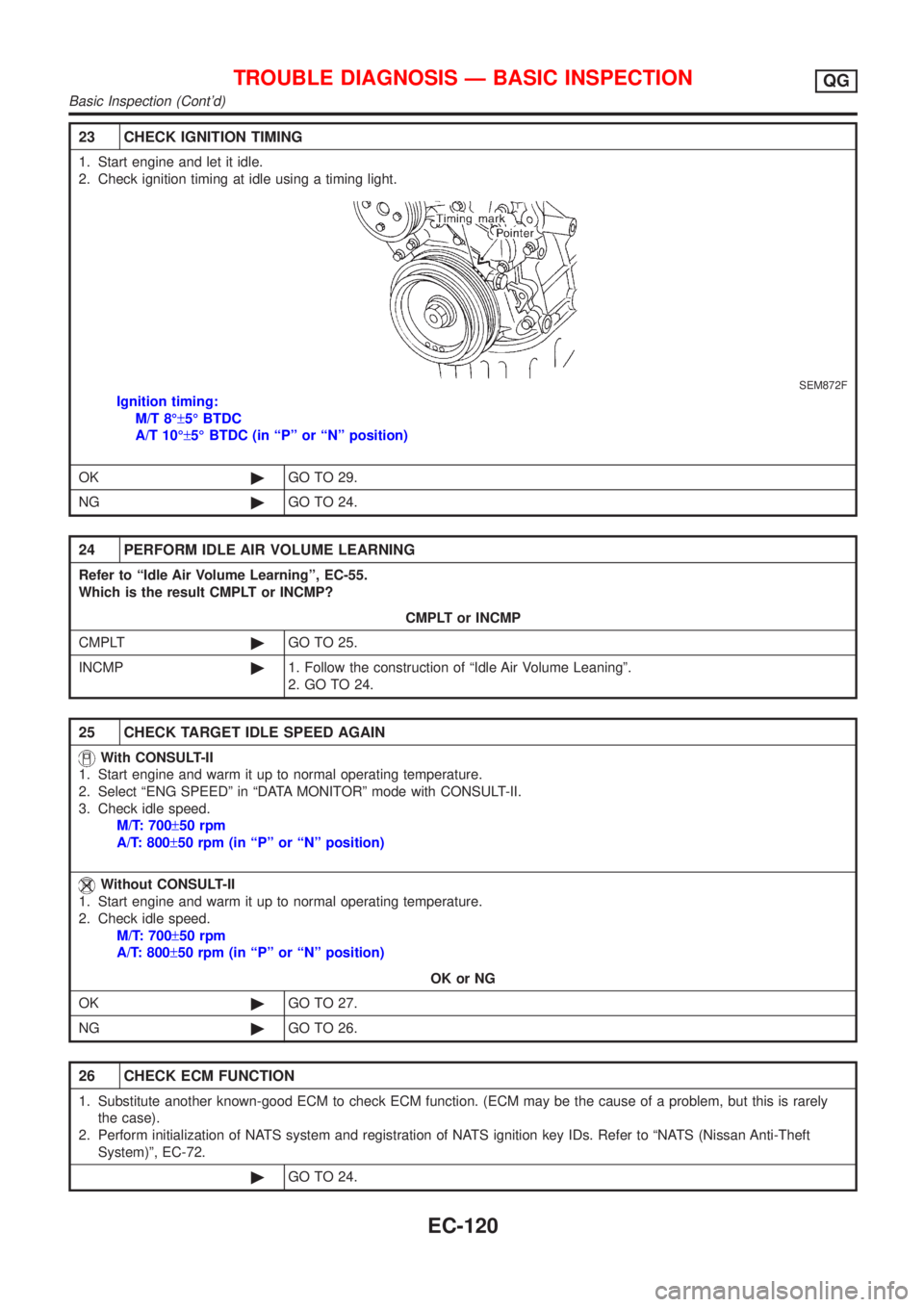
23 CHECK IGNITION TIMING
1. Start engine and let it idle.
2. Check ignition timing at idle using a timing light.
SEM872F
Ignition timing:
M/T 8ɱ5É BTDC
A/T 10ɱ5É BTDC (in ªPº or ªNº position)
OK©GO TO 29.
NG©GO TO 24.
24 PERFORM IDLE AIR VOLUME LEARNING
Refer to ªIdle Air Volume Learningº, EC-55.
Which is the result CMPLT or INCMP?
CMPLT or INCMP
CMPLT©GO TO 25.
INCMP©1. Follow the construction of ªIdle Air Volume Leaningº.
2. GO TO 24.
25 CHECK TARGET IDLE SPEED AGAIN
With CONSULT-II
1. Start engine and warm it up to normal operating temperature.
2. Select ªENG SPEEDº in ªDATA MONITORº mode with CONSULT-II.
3. Check idle speed.
M/T: 700±50 rpm
A/T: 800±50 rpm (in ªPº or ªNº position)
Without CONSULT-II
1. Start engine and warm it up to normal operating temperature.
2. Check idle speed.
M/T: 700±50 rpm
A/T: 800±50 rpm (in ªPº or ªNº position)
OK or NG
OK©GO TO 27.
NG©GO TO 26.
26 CHECK ECM FUNCTION
1. Substitute another known-good ECM to check ECM function. (ECM may be the cause of a problem, but this is rarely
the case).
2. Perform initialization of NATS system and registration of NATS ignition key IDs. Refer to ªNATS (Nissan Anti-Theft
System)º, EC-72.
©GO TO 24.
TROUBLE DIAGNOSIS Ð BASIC INSPECTIONQG
Basic Inspection (Cont'd)
EC-120
Page 424 of 2493

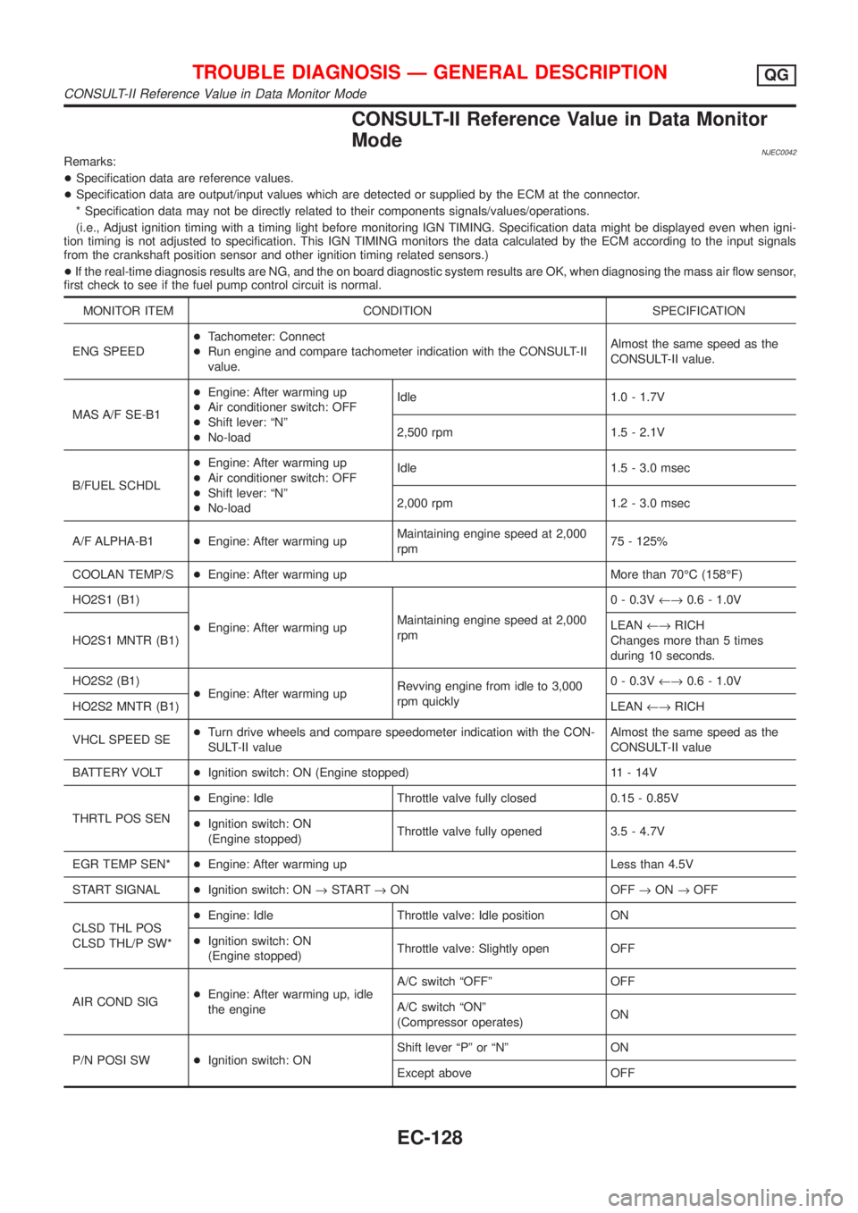
CONSULT-II Reference Value in Data Monitor
Mode
NJEC0042Remarks:
+Specification data are reference values.
+Specification data are output/input values which are detected or supplied by the ECM at the connector.
* Specification data may not be directly related to their components signals/values/operations.
(i.e., Adjust ignition timing with a timing light before monitoring IGN TIMING. Specification data might be displayed even when igni-
tion timing is not adjusted to specification. This IGN TIMING monitors the data calculated by the ECM according to the input signals
from the crankshaft position sensor and other ignition timing related sensors.)
+If the real-time diagnosis results are NG, and the on board diagnostic system results are OK, when diagnosing the mass air flow sensor,
first check to see if the fuel pump control circuit is normal.
MONITOR ITEM CONDITION SPECIFICATION
ENG SPEED+Tachometer: Connect
+Run engine and compare tachometer indication with the CONSULT-II
value.Almost the same speed as the
CONSULT-II value.
MAS A/F SE-B1+Engine: After warming up
+Air conditioner switch: OFF
+Shift lever: ªNº
+No-loadIdle 1.0 - 1.7V
2,500 rpm 1.5 - 2.1V
B/FUEL SCHDL+Engine: After warming up
+Air conditioner switch: OFF
+Shift lever: ªNº
+No-loadIdle 1.5 - 3.0 msec
2,000 rpm 1.2 - 3.0 msec
A/F ALPHA-B1+Engine: After warming upMaintaining engine speed at 2,000
rpm75 - 125%
COOLAN TEMP/S+Engine: After warming up More than 70ÉC (158ÉF)
HO2S1 (B1)
+Engine: After warming upMaintaining engine speed at 2,000
rpm0 - 0.3V¨0.6 - 1.0V
HO2S1 MNTR (B1)LEAN¨RICH
Changes more than 5 times
during 10 seconds.
HO2S2 (B1)
+Engine: After warming upRevving engine from idle to 3,000
rpm quickly0 - 0.3V¨0.6 - 1.0V
HO2S2 MNTR (B1)LEAN¨RICH
VHCL SPEED SE+Turn drive wheels and compare speedometer indication with the CON-
SULT-II valueAlmost the same speed as the
CONSULT-II value
BATTERY VOLT+Ignition switch: ON (Engine stopped) 11 - 14V
THRTL POS SEN+Engine: Idle Throttle valve fully closed 0.15 - 0.85V
+Ignition switch: ON
(Engine stopped)Throttle valve fully opened 3.5 - 4.7V
EGR TEMP SEN*+Engine: After warming up Less than 4.5V
START SIGNAL+Ignition switch: ON®START®ON OFF®ON®OFF
CLSD THL POS
CLSD THL/P SW*+Engine: Idle Throttle valve: Idle position ON
+Ignition switch: ON
(Engine stopped)Throttle valve: Slightly open OFF
AIR COND SIG+Engine: After warming up, idle
the engineA/C switch ªOFFº OFF
A/C switch ªONº
(Compressor operates)ON
P/N POSI SW+Ignition switch: ONShift lever ªPº or ªNº ON
Except above OFF
TROUBLE DIAGNOSIS Ð GENERAL DESCRIPTIONQG
CONSULT-II Reference Value in Data Monitor Mode
EC-128
Page 434 of 2493
![NISSAN ALMERA N16 2001 Electronic Repair Manual TERMI-
NAL
NO.WIRE
COLORITEM CONDITION DATA (DC Voltage)
72* P/B EGR temperature sensor[Engine is running]
+Warm-up condition
+Idle speedLess than 4.5V
[Engine is running]
+Warm-up condition
+EGR syst NISSAN ALMERA N16 2001 Electronic Repair Manual TERMI-
NAL
NO.WIRE
COLORITEM CONDITION DATA (DC Voltage)
72* P/B EGR temperature sensor[Engine is running]
+Warm-up condition
+Idle speedLess than 4.5V
[Engine is running]
+Warm-up condition
+EGR syst](/manual-img/5/57351/w960_57351-433.png)
TERMI-
NAL
NO.WIRE
COLORITEM CONDITION DATA (DC Voltage)
72* P/B EGR temperature sensor[Engine is running]
+Warm-up condition
+Idle speedLess than 4.5V
[Engine is running]
+Warm-up condition
+EGR system is operating0 - 1.0V
73 BMass air flow sensor
ground[Engine is running]
+Warm-up condition
+Idle speedApproximately 0V
74 R/LRefrigerant pressure
sensor[Engine is running]
+Air conditioner switch is ªONº
(Compressor operates)1.0 - 4.0V
[Engine is running]
+Warm-up condition
+Idle speed
+Air conditioner switch is turned from ªONº to
ªOFFºVoltage is gradually decreasing.
81 W Knock sensor[Engine is running]
+Idle speed1.0 - 4.0V
85 RCrankshaft position sen-
sor (POS)[Engine is running]
+Warm-up condition
+Idle speed3.0 - 4.0V
SEF979W
[Engine is running]
+Engine speed is 2,000 rpm3.0 - 4.0V
SEF980W
86 PU/R Vehicle speed sensor[Engine is running]
+Lift up the vehicle
+Vehicle speed is 40 km/h (25 MPH)2.5-3V
SEF976W
91 PU A/T check signal[Engine is running]
+Idle speed0 - Approximately 5V
92 Y Throttle position sensor[Engine is running]
+Accelerator pedal released0.15 - 0.85V
[Ignition switch ªONº]
+Accelerator pedal fully depressed3.5 - 4.7V
TROUBLE DIAGNOSIS Ð GENERAL DESCRIPTIONQG
ECM Terminals and Reference Value (Cont'd)
EC-138
Page 443 of 2493
2 CHECK ECM POWER SUPPLY CIRCUIT-I
1. Turn ignition switch ªOFFº and then ªONº.
2. Check voltage between ECM terminal 43 and ground with CONSULT-II or tester.
SEF291X
OK or NG
OK©GO TO 4.
NG©GO TO 3.
3 DETECT MALFUNCTIONING PART
Check the following.
+Harness connectors M169, F113
+Fuse block (J/B) connector M1, E103
+10A fuse
+Harness for open or short between ECM and ignition switch
©Repair harness or connectors.
4 CHECK ECM GROUND CIRCUIT FOR OPEN AND SHORT-I
1. Turn ignition switch ªOFFº.
2. Disconnect ECM harness connector.
3. Check harness continuity between ECM terminals 48, 57, 106, 108 and engine ground.
Refer to WIRING DIAGRAM.
Continuity should exist.
4. Also check harness for short to ground and short to power.
OK or NG
OK©GO TO 5.
NG©Repair open circuit or short to ground or short to power in harness or connectors.
TROUBLE DIAGNOSIS FOR POWER SUPPLYQG
Main Power Supply and Ground Circuit (Cont'd)
EC-147
Page 444 of 2493

5 CHECK POWER SUPPLY-II
1. Disconnect ECM relay. (For ECM relay location, refer to ªEngine Control Compartment Parts Locationº.)
2. Check voltage between ECM relay terminals 1, 6 and ground with CONSULT-II or tester.
SEF101Y
OK or NG
OK©GO TO 7.
NG©GO TO 6.
6 DETECT MALFUNCTIONING PART
Check the following.
+15A fuse and 10A fuse
+Harness for open or short between ECM relay and battery
©Repair open circuit or short to ground or short to power in harness or connectors.
7 CHECK OUTPUT SIGNAL CIRCUIT FOR OPEN AND SHORT
1. Check harness continuity between ECM terminal 31 and ECM relay terminal 2.
Continuity should exist.
2. Also check harness for short to ground and short to power.
OK or NG
OK©Go to ªIGNITION SIGNALº, EC-451.
NG©GO TO 8.
8 DETECT MALFUNCTIONING PART
Check the harness for open or short between ECM relay and ECM.
©Repair open circuit or short to ground or short to power in harness or connectors.
TROUBLE DIAGNOSIS FOR POWER SUPPLYQG
Main Power Supply and Ground Circuit (Cont'd)
EC-148
Page 445 of 2493
9 CHECK ECM POWER SUPPLY CIRCUIT-II
1. Stop engine.
2. Check voltage between ECM terminal 67 and ground with CONSULT-II or tester.
SEF293X
OK or NG
OK©GO TO 11.
NG©GO TO 10.
10 DETECT MALFUNCTIONING PART
Check the following.
+Harness connectors E174, M159
+Harness connectors M169, F113
+Harness for open or short between ECM and fuse
©Repair harness or connectors.
11 CHECK ECM POWER SUPPLY CIRCUIT-III
1. Turn ignition switch ªONº and then ªOFFº.
2. Check voltage between ECM terminals 110, 112 and ground with CONSULT-II or tester.
SEF294X
OK or NG
OK©GO TO 17.
NG (Battery voltage
does not exist.)©GO TO 12.
NG (Battery voltage
exists for more than a
few seconds.)©GO TO 14.
TROUBLE DIAGNOSIS FOR POWER SUPPLYQG
Main Power Supply and Ground Circuit (Cont'd)
EC-149
Page 446 of 2493

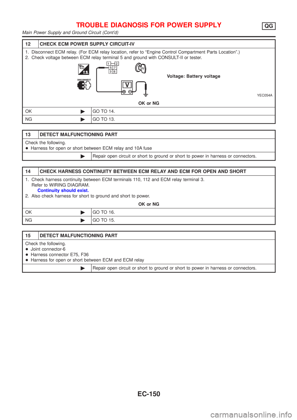
12 CHECK ECM POWER SUPPLY CIRCUIT-IV
1. Disconnect ECM relay. (For ECM relay location, refer to ªEngine Control Compartment Parts Locationº.)
2. Check voltage between ECM relay terminal 5 and ground with CONSULT-II or tester.
YEC054A
OK or NG
OK©GO TO 14.
NG©GO TO 13.
13 DETECT MALFUNCTIONING PART
Check the following.
+Harness for open or short between ECM relay and 10A fuse
©Repair open circuit or short to ground or short to power in harness or connectors.
14 CHECK HARNESS CONTINUITY BETWEEN ECM RELAY AND ECM FOR OPEN AND SHORT
1. Check harness continuity between ECM terminals 110, 112 and ECM relay terminal 3.
Refer to WIRING DIAGRAM.
Continuity should exist.
2. Also check harness for short to ground and short to power.
OK or NG
OK©GO TO 16.
NG©GO TO 15.
15 DETECT MALFUNCTIONING PART
Check the following.
+Joint connector-6
+Harness connector E75, F36
+Harness for open or short between ECM and ECM relay
©Repair open circuit or short to ground or short to power in harness or connectors.
TROUBLE DIAGNOSIS FOR POWER SUPPLYQG
Main Power Supply and Ground Circuit (Cont'd)
EC-150
Page 447 of 2493
16 CHECK ECM RELAY
1. Apply 12V direct current between ECM relay terminals 1 and 2.
2. Check continuity between relay terminals 3 and 5, 6 and 7.
SEF296X
OK or NG
OK©GO TO 17.
NG©Replace ECM relay.
17 CHECK ECM GROUND CIRCUIT FOR OPEN AND SHORT-II
1. Turn ignition switch ªOFFº.
2. Disconnect ECM harness connector.
3. Check harness continuity between ECM terminals 48, 57, 106, 108 and engine ground.
Refer to WIRING DIAGRAM.
Continuity should exist.
4. Also check harness for short to ground and short to power.
OK or NG
OK©GO TO 18.
NG©Repair open circuit or short to ground or short to power in harness or connectors.
18 CHECK INTERMITTENT INCIDENT
Refer to ªTROUBLE DIAGNOSIS FOR INTERMITTENT INCIDENTº, EC-144.
©INSPECTION END
TROUBLE DIAGNOSIS FOR POWER SUPPLYQG
Main Power Supply and Ground Circuit (Cont'd)
EC-151