Page 2209 of 2493

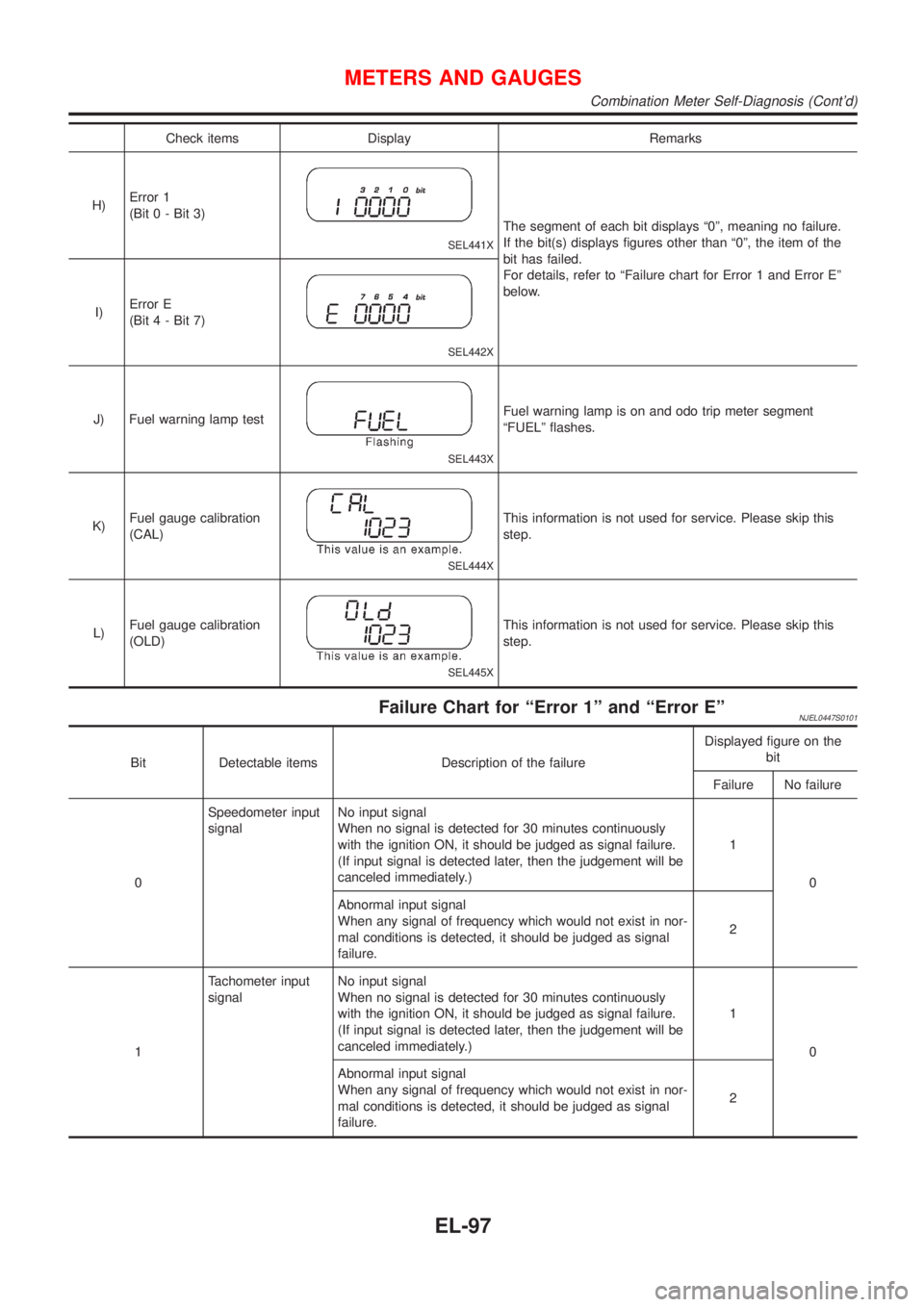
Check items Display Remarks
H)Error 1
(Bit 0 - Bit 3)
SEL441X
The segment of each bit displays ª0º, meaning no failure.
If the bit(s) displays figures other than ª0º, the item of the
bit has failed.
For details, refer to ªFailure chart for Error 1 and Error Eº
below.
I)Error E
(Bit 4 - Bit 7)
SEL442X
J) Fuel warning lamp test
SEL443X
Fuel warning lamp is on and odo trip meter segment
ªFUELº flashes.
K)Fuel gauge calibration
(CAL)
SEL444X
This information is not used for service. Please skip this
step.
L)Fuel gauge calibration
(OLD)
SEL445X
This information is not used for service. Please skip this
step.
Failure Chart for ªError 1º and ªError EºNJEL0447S0101
Bit Detectable items Description of the failureDisplayed figure on the
bit
Failure No failure
0Speedometer input
signalNo input signal
When no signal is detected for 30 minutes continuously
with the ignition ON, it should be judged as signal failure.
(If input signal is detected later, then the judgement will be
canceled immediately.)1
0
Abnormal input signal
When any signal of frequency which would not exist in nor-
mal conditions is detected, it should be judged as signal
failure.2
1Tachometer input
signalNo input signal
When no signal is detected for 30 minutes continuously
with the ignition ON, it should be judged as signal failure.
(If input signal is detected later, then the judgement will be
canceled immediately.)1
0
Abnormal input signal
When any signal of frequency which would not exist in nor-
mal conditions is detected, it should be judged as signal
failure.2
METERS AND GAUGES
Combination Meter Self-Diagnosis (Cont'd)
EL-97
Page 2210 of 2493

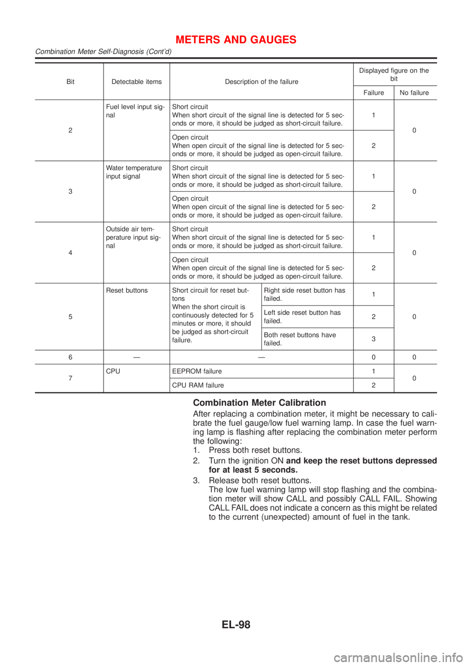
Bit Detectable items Description of the failureDisplayed figure on the
bit
Failure No failure
2Fuel level input sig-
nalShort circuit
When short circuit of the signal line is detected for 5 sec-
onds or more, it should be judged as short-circuit failure.1
0
Open circuit
When open circuit of the signal line is detected for 5 sec-
onds or more, it should be judged as open-circuit failure.2
3Water temperature
input signalShort circuit
When short circuit of the signal line is detected for 5 sec-
onds or more, it should be judged as short-circuit failure.1
0
Open circuit
When open circuit of the signal line is detected for 5 sec-
onds or more, it should be judged as open-circuit failure.2
4Outside air tem-
perature input sig-
nalShort circuit
When short circuit of the signal line is detected for 5 sec-
onds or more, it should be judged as short-circuit failure.1
0
Open circuit
When open circuit of the signal line is detected for 5 sec-
onds or more, it should be judged as open-circuit failure.2
5Reset buttons Short circuit for reset but-
tons
When the short circuit is
continuously detected for 5
minutes or more, it should
be judged as short-circuit
failure.Right side reset button has
failed.1
0 Left side reset button has
failed.2
Both reset buttons have
failed.3
6Ð Ð 00
7CPU EEPROM failure 1
0
CPU RAM failure 2
Combination Meter Calibration
After replacing a combination meter, it might be necessary to cali-
brate the fuel gauge/low fuel warning lamp. In case the fuel warn-
ing lamp is flashing after replacing the combination meter perform
the following:
1. Press both reset buttons.
2. Turn the ignition ONand keep the reset buttons depressed
for at least 5 seconds.
3. Release both reset buttons.
The low fuel warning lamp will stop flashing and the combina-
tion meter will show CALL and possibly CALL FAIL. Showing
CALL FAIL does not indicate a concern as this might be related
to the current (unexpected) amount of fuel in the tank.
METERS AND GAUGES
Combination Meter Self-Diagnosis (Cont'd)
EL-98
Page 2219 of 2493
SchematicNJEL0450
YEL652C
WARNING LAMPS
Schematic
EL-107
Page 2220 of 2493
Wiring Diagram Ð WARN ÐNJEL0451
YEL653C
WARNING LAMPS
Wiring Diagram Ð WARN Ð
EL-108
Page 2221 of 2493
YEL654C
WARNING LAMPS
Wiring Diagram Ð WARN Ð (Cont'd)
EL-109
Page 2222 of 2493
YEL655C
WARNING LAMPS
Wiring Diagram Ð WARN Ð (Cont'd)
EL-110
Page 2223 of 2493
YEL656C
WARNING LAMPS
Wiring Diagram Ð WARN Ð (Cont'd)
EL-111
Page 2224 of 2493

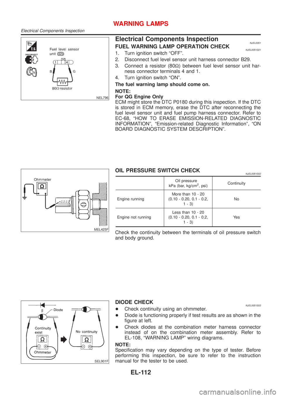
NEL796
Electrical Components InspectionNJEL0051FUEL WARNING LAMP OPERATION CHECKNJEL0051S011. Turn ignition switch ªOFFº.
2. Disconnect fuel level sensor unit harness connector B29.
3. Connect a resistor (80W) between fuel level sensor unit har-
ness connector terminals 4 and 1.
4. Turn ignition switch ªONº.
The fuel warning lamp should come on.
NOTE:
For QG Engine Only
ECM might store the DTC P0180 during this inspection. If the DTC
is stored in ECM memory, erase the DTC after reconnecting the
fuel level sensor unit and fuel pump harness connector. Refer to
EC-68, ªHOW TO ERASE EMISSION-RELATED DIAGNOSTIC
INFORMATIONº, ªEmission-related Diagnostic Informationº, ªON
BOARD DIAGNOSTIC SYSTEM DESCRIPTIONº.
MEL425F
OIL PRESSURE SWITCH CHECKNJEL0051S02
Oil pressure
kPa (bar, kg/cm2, psi)Continuity
Engine runningMore than 10 - 20
(0.10 - 0.20, 0.1 - 0.2,
1-3)No
Engine not runningLess than 10 - 20
(0.10 - 0.20, 0.1 - 0.2,
1-3)Ye s
Check the continuity between the terminals of oil pressure switch
and body ground.
SEL901F
DIODE CHECKNJEL0051S03+Check continuity using an ohmmeter.
+Diode is functioning properly if test results are as shown in the
figure at left.
+Check diodes at the combination meter harness connector
instead of on the combination meter assembly. Refer to
EL-108, ªWARNING LAMPº wiring diagrams.
NOTE:
Specification may vary depending on the type of tester. Before
performing this inspection, be sure to refer to the instruction
manual for the tester to be used.
WARNING LAMPS
Electrical Components Inspection
EL-112