2001 NISSAN ALMERA N16 warning
[x] Cancel search: warningPage 2233 of 2493
DIAGNOSTIC PROCEDURE 4NJEL0455S06
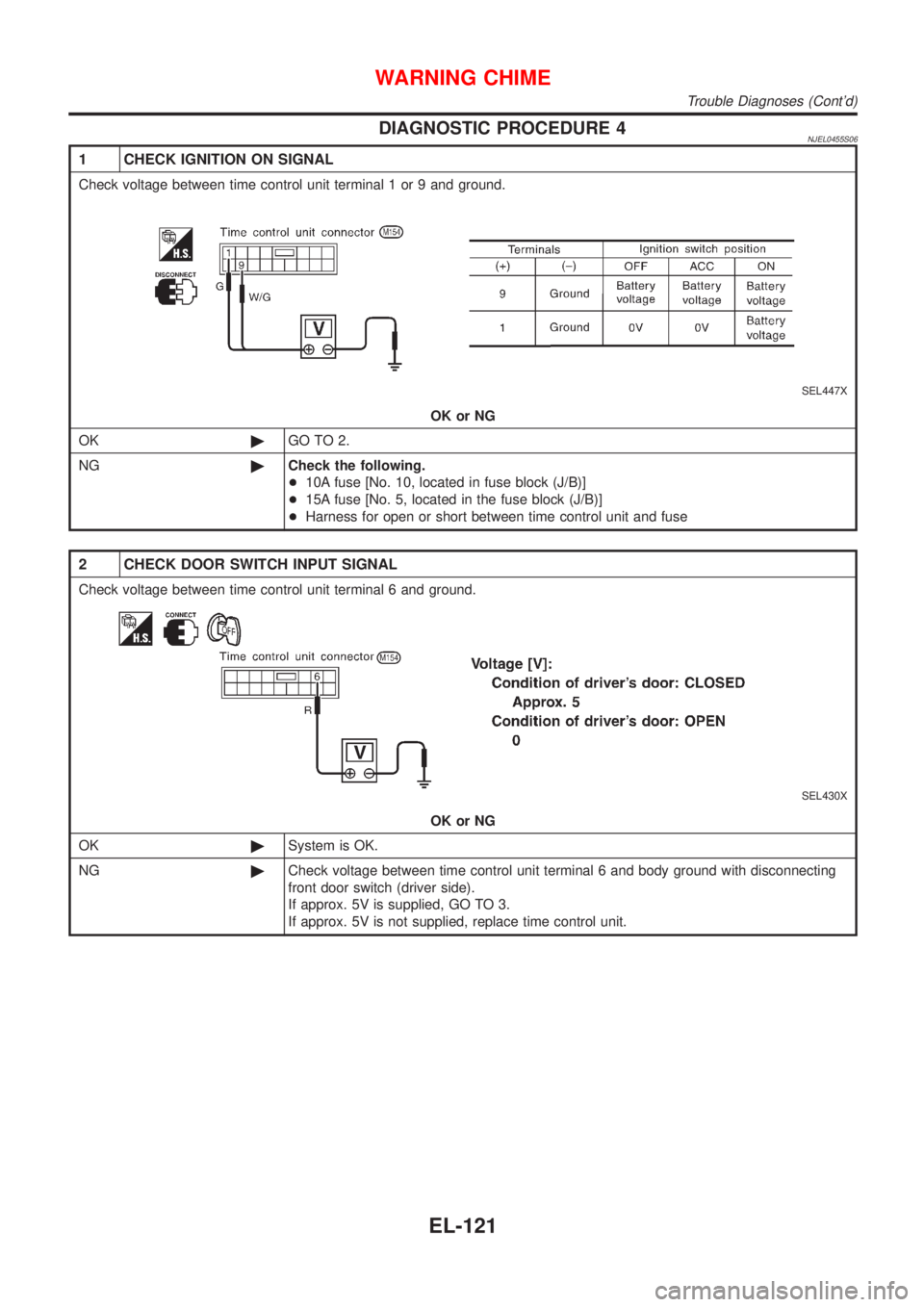
1 CHECK IGNITION ON SIGNAL
Check voltage between time control unit terminal 1 or 9 and ground.
SEL447X
OK or NG
OK©GO TO 2.
NG©Check the following.
+10A fuse [No. 10, located in fuse block (J/B)]
+15A fuse [No. 5, located in the fuse block (J/B)]
+Harness for open or short between time control unit and fuse
2 CHECK DOOR SWITCH INPUT SIGNAL
Check voltage between time control unit terminal 6 and ground.
SEL430X
OK or NG
OK©System is OK.
NG©Check voltage between time control unit terminal 6 and body ground with disconnecting
front door switch (driver side).
If approx. 5V is supplied, GO TO 3.
If approx. 5V is not supplied, replace time control unit.
WARNING CHIME
Trouble Diagnoses (Cont'd)
EL-121
Page 2234 of 2493
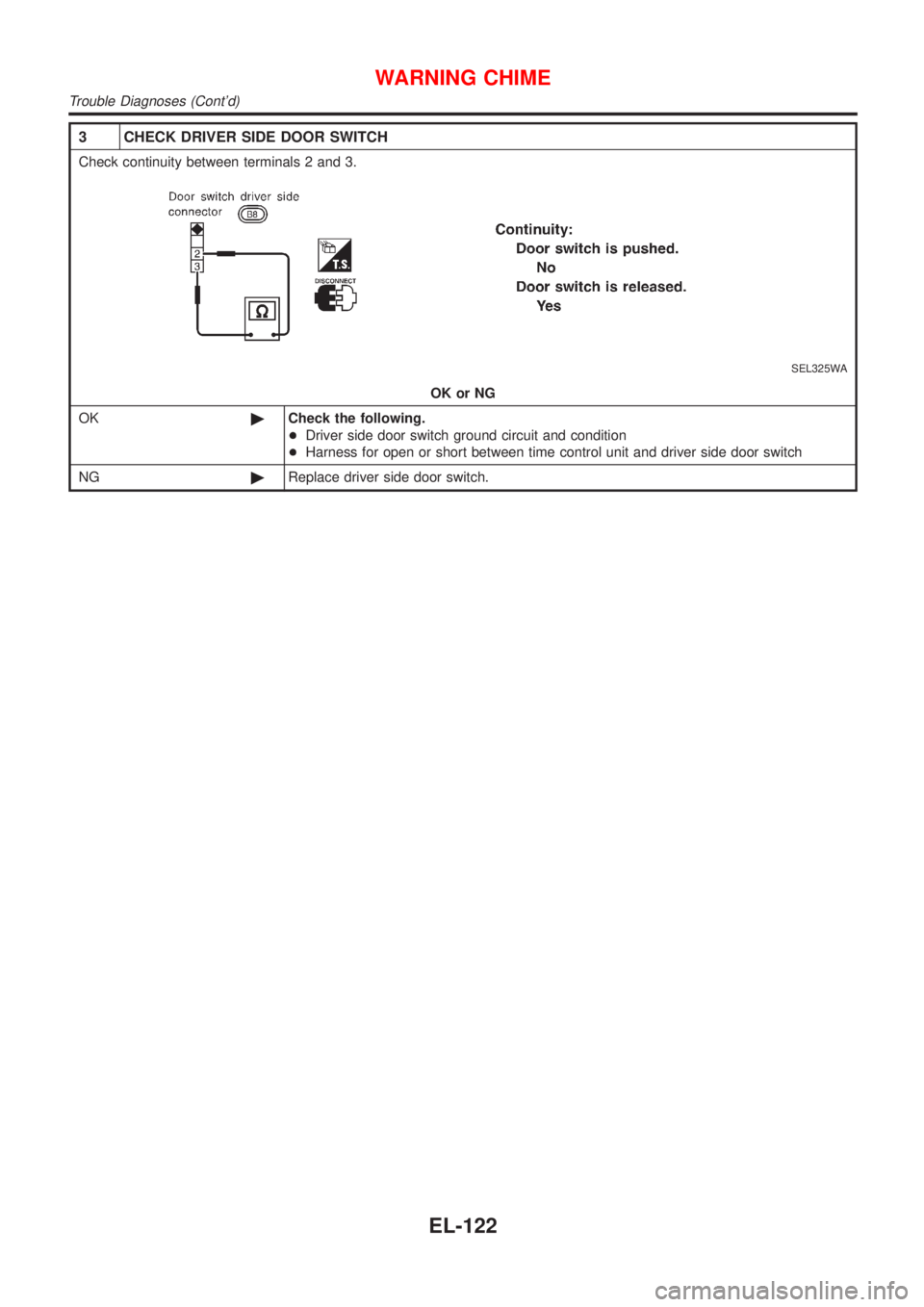
3 CHECK DRIVER SIDE DOOR SWITCH
Check continuity between terminals 2 and 3.
SEL325WA
OK or NG
OK©Check the following.
+Driver side door switch ground circuit and condition
+Harness for open or short between time control unit and driver side door switch
NG©Replace driver side door switch.
WARNING CHIME
Trouble Diagnoses (Cont'd)
EL-122
Page 2338 of 2493
IGNITION ªONº POWER SUPPLY CIRCUIT FOR TIME
CONTROL UNIT
=NJEL0482S17
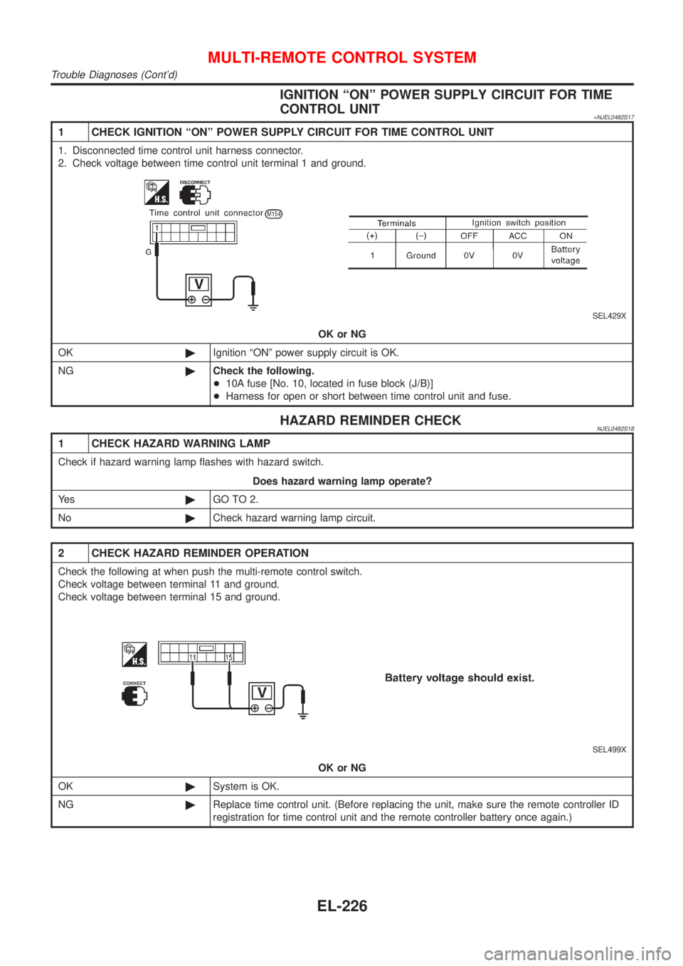
1 CHECK IGNITION ªONº POWER SUPPLY CIRCUIT FOR TIME CONTROL UNIT
1. Disconnected time control unit harness connector.
2. Check voltage between time control unit terminal 1 and ground.
SEL429X
OK or NG
OK©Ignition ªONº power supply circuit is OK.
NG©Check the following.
+10A fuse [No. 10, located in fuse block (J/B)]
+Harness for open or short between time control unit and fuse.
HAZARD REMINDER CHECKNJEL0482S18
1 CHECK HAZARD WARNING LAMP
Check if hazard warning lamp flashes with hazard switch.
Does hazard warning lamp operate?
Ye s©GO TO 2.
No©Check hazard warning lamp circuit.
2 CHECK HAZARD REMINDER OPERATION
Check the following at when push the multi-remote control switch.
Check voltage between terminal 11 and ground.
Check voltage between terminal 15 and ground.
SEL499X
OK or NG
OK©System is OK.
NG©Replace time control unit. (Before replacing the unit, make sure the remote controller ID
registration for time control unit and the remote controller battery once again.)
MULTI-REMOTE CONTROL SYSTEM
Trouble Diagnoses (Cont'd)
EL-226
Page 2341 of 2493
Description=NJEL0485The TCU has the following functions.
INTERIOR LAMP TIMERNJEL0485S01The interior lamp timer is controlled by the TCU.
For further information, refer to ªINTERIOR ROOM LAMPº (EL-76).
IGNITION KEY WARNING CHIME AND LIGHT WARNING CHIMENJEL0485S02The ignition key and light warning chime are controlled by the TCU.
For further information, refer to ªWARNING CHIMEº (EL-113).
REAR WINDOW DEFOGGER TIMERNJEL0485S03The rear window defogger and door mirror defogger system are controlled by the TCU.
For further information, refer to ªREAR WINDOW DEFOGGERº (EL-138).
POWER DOOR LOCK (SUPER LOCK)NJEL0485S04The power door lock (super lock) is controlled by the TCU.
For further information, refer to ªPOWER DOOR LOCK Ð Super Lock к (EL-196).
MULTI-REMOTE CONTROL SYSTEMNJEL0485S05The multi-remote control system is controlled by the TCU.
For further information, refer to ªMULTI-REMOTE CONTROL SYSTEMº (EL-220).
FUNCTIONNJEL0485S06+The TCU has the following control function.
Item Details of control
Direction indicatorsSwitches the director indicators (Left, Right or All) when the combination
switch or hazard switch is operated.
Light warning chimeSounds warning chime when driver's door is opened with light switch in the
1st or 2nd position and ignition switch ªOFFº.
Ignition key warning chineSounds warning chime when driver's door is opened with key in ignition and
the driver door lock knob (unlock sensor) is moved from the ªunlockº posi-
tion to the ªlockº position.
Rear window defogger timerTurn off rear window defogger and door mirror heater, if equipped, about 15
minutes after the rear window defogger switch is turned ªONº.
Battery saverShuts off interior lamp in 30 minutes if any door is left open when ignition
switch is ªOFFº. The battery saver will reset if ignition switch is cycled or any
door is opened or closed.
Interior lamp timerKeep interior lamp illuminated for about 30 seconds when:
+driver's door is unlocked,
+the ignition is switched off,
+driver's door is opened and then closed.
The timer is cancelled, and interior lamp turns off when:
+driver's door is locked, or
+ignition switch is turned ªONº.
Power door lock Centrally locks and unlocks the vehicle
Super lock Activates and de-activates the super lock system.
TIME CONTROL UNIT
Description
EL-229
Page 2371 of 2493

PrecautionsNJEL0514WARNING:
Do not attempt to disassemble the monitor. Parts of the monitor have high voltages that can result in
severe and dangerous electric shock.
CAUTION:
+Do not reverse battery connections.
+Do not attach unauthorized parts.
+Protect the unit from severe impact.
NOTE:
Before beginning repair, determine whether or not the unit is defective. Refer to ªThis Condition Is Not
Abnormalº (EL-309).
NAVIGATION SYSTEM
Precautions
EL-259
Page 2479 of 2493
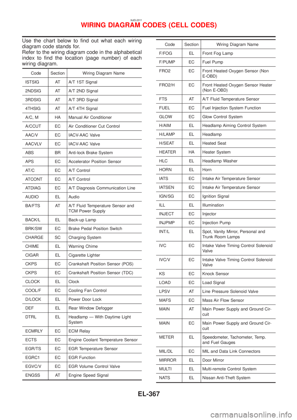
NJEL0311
Use the chart below to find out what each wiring
diagram code stands for.
Refer to the wiring diagram code in the alphabetical
index to find the location (page number) of each
wiring diagram.
Code Section Wiring Diagram Name
ISTSIG AT A/T 1ST Signal
2NDSIG AT A/T 2ND Signal
3RDSIG AT A/T 3RD Signal
4THSIG AT A/T 4TH Signal
A/C, M HA Manual Air Conditioner
A/CCUT EC Air Conditioner Cut Control
AAC/V EC IACV-AAC Valve
AACVLV EC IACV-AAC Valve
ABS BR Anti-lock Brake System
APS EC Accelerator Position Sensor
AT/C EC A/T Control
ATCONT EC A/T Control
ATDIAG EC A/T Diagnosis Communication Line
AUDIO EL Audio
BA/FTS AT A/T Fluid Temperature Sensor and
TCM Power Supply
BACK/L EL Back-up Lamp
BRK/SW EC Brake Pedal Position Switch
CHARGE SC Charging System
CHIME EL Warning Chime
CIGAR EL Cigarette Lighter
CKPS EC Crankshaft Position Sensor (POS)
CKPS EC Crankshaft Position Sensor (TDC)
CLOCK EL Clock
COOL/F EC Cooling Fan Control
D/LOCK EL Power Door Lock
DEF EL Rear Window Defogger
DTRL EL Headlamp Ð With Daytime Light
System
ECMRLY EC ECM Relay
ECTS EC Engine Coolant Temperature Sensor
EGR/TS EC EGR Temperature Sensor
EGRC1 EC EGR Function
EGVC/V EC EGR Volume Control Valve
ENGSS AT Engine Speed Signal
Code Section Wiring Diagram Name
F/FOG EL Front Fog Lamp
F/PUMP EC Fuel Pump
FRO2 EC Front Heated Oxygen Sensor (Non
E-OBD)
FRO2/H EC Front Heated Oxygen Sensor Heater
(Non E-OBD)
FTS AT A/T Fluid Temperature Sensor
FUEL EC Fuel Injection System Function
GLOW EC Glow Control System
H/AIM EL Headlamp Aiming Control System
H/LAMP EL Headlamp
H/SEAT EL Heated Seat
HEATER HA Heater System
HLC EL Headlamp Washer
HORN EL Horn
IATS EC Intake Air Temperature Sensor
IATSEN EC Intake Air Temperature Sensor
IGN/SG EC Ignition Signal
ILL EL Illumination
INJECT EC Injector
INJPMP EC Injection Pump
INT/L EL Spot, Vanity Mirror, Personal and
Trunk Room Lamps
IVC EC Intake Valve Timing Control Solenoid
Valve
IVC/V EC Intake Valve Timing Control Solenoid
Valve
KS EC Knock Sensor
LOAD EC Load Signal
LPSV AT Line Pressure Solenoid Valve
MAFS EC Mass Air Flow Sensor
MAIN AT Main Power Supply and Ground Cir-
cuit
MAIN EC Main Power Supply and Ground Cir-
cuit
METER EL Speedometer, Tachometer, Temp.
and Fuel Gauges
MIL/DL EC MIL and Data Link Connectors
MIRROR EL Door Mirror
MULTI EL Multi-remote Control System
NATS EL Nissan Anti-Theft System
WIRING DIAGRAM CODES (CELL CODES)
EL-367
Page 2480 of 2493
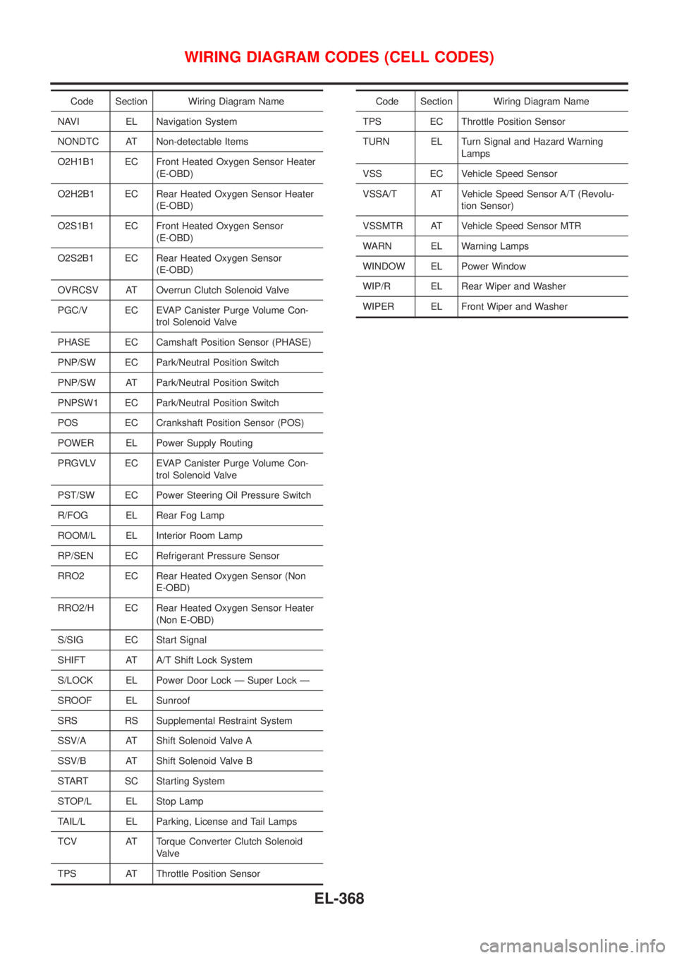
Code Section Wiring Diagram Name
NAVI EL Navigation System
NONDTC AT Non-detectable Items
O2H1B1 EC Front Heated Oxygen Sensor Heater
(E-OBD)
O2H2B1 EC Rear Heated Oxygen Sensor Heater
(E-OBD)
O2S1B1 EC Front Heated Oxygen Sensor
(E-OBD)
O2S2B1 EC Rear Heated Oxygen Sensor
(E-OBD)
OVRCSV AT Overrun Clutch Solenoid Valve
PGC/V EC EVAP Canister Purge Volume Con-
trol Solenoid Valve
PHASE EC Camshaft Position Sensor (PHASE)
PNP/SW EC Park/Neutral Position Switch
PNP/SW AT Park/Neutral Position Switch
PNPSW1 EC Park/Neutral Position Switch
POS EC Crankshaft Position Sensor (POS)
POWER EL Power Supply Routing
PRGVLV EC EVAP Canister Purge Volume Con-
trol Solenoid Valve
PST/SW EC Power Steering Oil Pressure Switch
R/FOG EL Rear Fog Lamp
ROOM/L EL Interior Room Lamp
RP/SEN EC Refrigerant Pressure Sensor
RRO2 EC Rear Heated Oxygen Sensor (Non
E-OBD)
RRO2/H EC Rear Heated Oxygen Sensor Heater
(Non E-OBD)
S/SIG EC Start Signal
SHIFT AT A/T Shift Lock System
S/LOCK EL Power Door Lock Ð Super Lock Ð
SROOF EL Sunroof
SRS RS Supplemental Restraint System
SSV/A AT Shift Solenoid Valve A
SSV/B AT Shift Solenoid Valve B
START SC Starting System
STOP/L EL Stop Lamp
TAIL/L EL Parking, License and Tail Lamps
TCV AT Torque Converter Clutch Solenoid
Valve
TPS AT Throttle Position SensorCode Section Wiring Diagram Name
TPS EC Throttle Position Sensor
TURN EL Turn Signal and Hazard Warning
Lamps
VSS EC Vehicle Speed Sensor
VSSA/T AT Vehicle Speed Sensor A/T (Revolu-
tion Sensor)
VSSMTR AT Vehicle Speed Sensor MTR
WARN EL Warning Lamps
WINDOW EL Power Window
WIP/R EL Rear Wiper and Washer
WIPER EL Front Wiper and Washer
WIRING DIAGRAM CODES (CELL CODES)
EL-368
Page 2484 of 2493

Engine control module (ECM) ....... EC-327, 554,
604, 664, 666, 670, 672
Engine control system diagram and
chart .............................................. EC-26, 503
Engine coolant temperature sensor
(ECTS) ........................................ EC-163, 572
Engine fail-safe system ........................... EC-123
Engine oil precautions .................................. GI-7
Engine outer component parts ................. EM-11
Engine removal ................................ EM-49, 136
Engine room - See Engine
compartment .......................................... BT-75
Engine serial number ................................. GI-41
Evaporative emission (EVAP)
system ................................................... EC-33
Exhaust gas recirculation (EGR)
valve .................................... EC-285, 353, 400
Exhaust system ................................... FE-11, 27
Exterior ...................................................... BT-47
F
F/PUMP - Wiring diagram ....................... EC-466
FR02 - Wiring diagram ... EC-179, 198, 205, 374
FR02/H - Wiring diagram ................ EC-211, 380
FUEL - Wiring diagram ................... EC-250, 257
Fan switch ................................................. HA-60
Final drive (FF A/T) .................................. AT-424
Final drive (FF M/T) .............. MT-43, 77, 93, 107
Finisher, interior - See Trim ....................... BT-31
Finisher, trunk lid ....................................... BT-45
Floor trim ................................................... BT-31
Fluid temperature sensor (A/T) ................ AT-192
Fluids ........................................................ MA-20
Flywheel (clutch) ....................................... CL-22
Flywheel runout ................................ EM-60, 153
Fog lamp, front, removal and
installation ................................................ BT-7
Fog lamp, front .......................................... EL-60
Fork rod (M/T) .............................. MT-32, 56, 94
Forward clutch ......................................... AT-399
Freeze frame data .............................. EC-59, 70
Front axle .................................................... AX-2
Front bumper ............................................... BT-7
Front combination lamp removal and
installation ................................................ BT-7
Front disc brake ........................................ BR-27
Front door .................................................. BT-16
Front fog lamp removal and
installation ................................................ BT-7
Front fog lamp ........................................... EL-60
Front heated oxygen sensor (HO2S)
heater .......................................... EC-209, 379
Front heated oxygen sensor (HO2S) ..... EC-176,
183, 189, 195, 203, 373
Front seat belt ............................................. RS-5
Front seat .................................................. BT-56
Front suspension ........................................ SU-2
Front washer ............................................ EL-123Front wiper ............................................... EL-123
Fuel cut control (at no load & high
engine speed) ............................... EC-33, 507
Fuel gauge ................................................. EL-89
Fuel injection system .............. EC-248, 255, 505
Fuel injector ............................................ EC-446
Fuel precautions ........................................... GI-8
Fuel pressure check ................................. EC-38
Fuel pressure regulator ............................. EC-39
Fuel pressure release ............................... EC-38
Fuel pump relay ...................................... EC-464
Fuel pump ............................................... EC-464
Fuel system ........................................... FE-5, 16
Fuel tank vacuum relief valve ................... EC-34
Fuse block ............................................... EL-369
Fuse ........................................................... EL-22
Fusible link ................................................. EL-22
G
GLOW - Wiring diagram ......................... EC-677
Garage jack and safety stand .................... GI-45
Gauges ...................................................... EL-89
Gear components (M/T) ............... MT-31, 55, 93
Generator - See Alternator ....................... SC-27
Generic scan tool (GST) ........................... EC-92
Glass .......................................................... BT-17
Glow plug ................................................ EC-677
Glow relay ............................................... EC-677
Grease ...................................................... MA-20
Ground distribution .................................... EL-23
H
H/LAMP - Wiring diagram .......................... EL-40
HEATER - Wiring diagram ........................ HA-24
HFC134a (R134a) system
recaution .................................................. HA-2
HFC134a (R134a) system service
procedure .............................................. HA-84
HFC134a (R134a) system service
tools ....................................................... HA-11
HFC134a system service equipment
precaution ................................................ HA-6
HORN - Wiring diagram .......................... EL-135
HSEAT - Wiring diagram ......................... EL-163
Harness connector ...................................... EL-5
Harness layout ......................................... EL-324
Hazard warning lamp ................................ EL-65
Headlamp removal and installation ............. BT-7
Headlamp washer .................................... EL-133
Headlamp .................................................. EL-40
Headlining - See Roof trim ........................ BT-43
Heated oxygen sensor (HO2S)
(front) .......... EC-176, 183, 189, 195, 203, 373
Heated oxygen sensor (HO2S) heater
(front) ........................................... EC-209, 379
ALPHABETICAL INDEX
IDX-4