Page 312 of 2493

Supplemental Restraint System (SRS) ªAIR
BAGº and ªSEAT BELT PRE-TENSIONERº
NJEC0002The Supplemental Restraint System such as ªAIR BAGº and ªSEAT BELT PRE-TENSIONERº used along with
a seat belt, helps to reduce the risk or severity of injury to the driver and front passenger for certain types of
collision. The SRS system composition which is available to NISSAN MODEL N16 is as follows (The compo-
sition varies according to the destination and optional equipment.):
+For a frontal collision
The Supplemental Restraint System consists of driver air bag module (located in the center of the steer-
ing wheel), front passenger air bag module (located on the instrument panel on passenger side), front seat
belt pre-tensioners, a diagnoses sensor unit, warning lamp, wiring harness and spiral cable.
+For a side collision
The Supplemental Restraint System consists of front side air bag module (located in the outer side of front
seat), side air bag (satellite) sensor, diagnoses sensor unit (one of components of air bags for a frontal
collision), wiring harness, warning lamp (one of components of air bags for a frontal collision).
Information necessary to service the system safely is included in theRS sectionof this Service Manual.
WARNING:
+To avoid rendering the SRS inoperative, which could increase the risk of personal injury or death
in the event of a collision which would result in air bag inflation, all maintenance should be per-
formed by an authorized NISSAN dealer.
+Improper maintenance, including incorrect removal and installation of the SRS, can lead to per-
sonal injury caused by unintentional activation of the system. For removal of Spiral Cable and Air
Bag Module, see the RS section.
+Do not use electrical test equipment on any circuit related to the SRS unless instructed to in this
Service Manual. SRS wiring harness can be identified by yellow harness connector.
Precautions for On Board Diagnostic (OBD)
System of Engine and A/T
NJEC0003The ECM has an on board diagnostic system. It will light up the malfunction indicator (MI) to warn the driver
of a malfunction causing emission deterioration.
CAUTION:
+Be sure to turn the ignition switch ªOFFº and disconnect the negative battery terminal before any
repair or inspection work. The open/short circuit of related switches, sensors, solenoid valves, etc.
will cause the MI to light up.
+Be sure to connect and lock the connectors securely after work. A loose (unlocked) connector will
cause the MI to light up due to the open circuit. (Be sure the connector is free from water, grease,
dirt, bent terminals, etc.)
+Certain systems and components, especially those related to OBD, may use a new style slide-
locking type harness connector.
For description and how to disconnect, refer to EL section, ªDescriptionº, ªHARNESS CONNEC-
TORº.
+Be sure to route and secure the harnesses properly after work. The interference of the harness with
a bracket, etc. may cause the MI to light up due to the short circuit.
+Be sure to connect rubber tubes properly after work. A misconnected or disconnected rubber tube
may cause the MI to light up due to the malfunction of fuel injection system, etc.
+Be sure to erase the unnecessary malfunction information (repairs completed) from the ECM and
TCM (Transmission Control Module) before returning the vehicle to the customer.
PRECAUTIONSQG
Supplemental Restraint System (SRS) ªAIR BAGº and ªSEAT BELT PRE-TENSIONERº
EC-16
Page 316 of 2493
Special Service ToolsNJEC0007
Tool number
Tool nameDescription
KV10117100
Heated oxygen sensor
wrench
NT379
Loosening or tightening heated oxygen sensor 1
(front) with 22 mm hexagon nut
KV10114400
Heated oxygen sensor
wrench
NT636
Loosening or tightening heated oxygen sensor 2
(rear)
a: 22 mm
Commercial Service ToolsNJEC0008
Tool name Description
Fuel filler cap adapter
NT653
Checking fuel tank vacuum relief valve opening
pressure
Oxygen sensor thread
cleaner
NT778
Reconditioning the exhaust system threads before
installing a new oxygen sensor. Use with anti-
seize lubricant shown below.
a: 18 mm dia. with pitch 1.5 mm, for Zirconia
Oxygen Sensor
b: 12 mm dia. with pitch 1.25 mm, for Titania
Oxygen Sensor
Anti-seize lubricant (Per-
matex
TM133AR or
equivalent meeting MIL
specification MIL-A-907)
NT779
Lubricating oxygen sensor thread cleaning tool
when reconditioning exhaust system threads.
PREPARATIONQG
Special Service Tools
EC-20
Page 334 of 2493

SEF094Y
SEF214Y
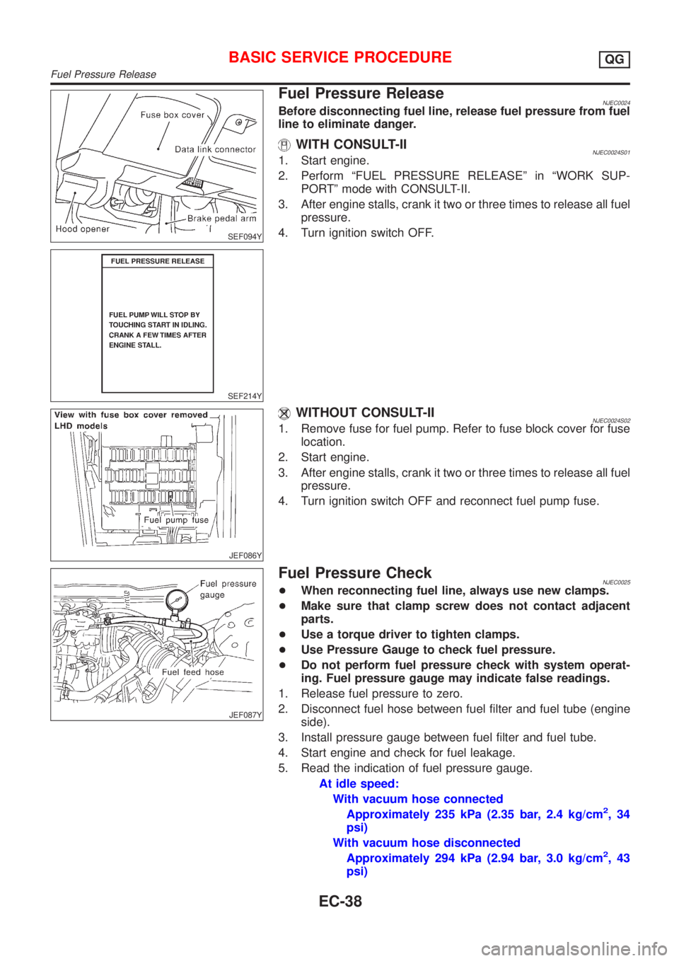
Fuel Pressure ReleaseNJEC0024Before disconnecting fuel line, release fuel pressure from fuel
line to eliminate danger.
WITH CONSULT-IINJEC0024S011. Start engine.
2. Perform ªFUEL PRESSURE RELEASEº in ªWORK SUP-
PORTº mode with CONSULT-II.
3. After engine stalls, crank it two or three times to release all fuel
pressure.
4. Turn ignition switch OFF.
JEF086Y
WITHOUT CONSULT-IINJEC0024S021. Remove fuse for fuel pump. Refer to fuse block cover for fuse
location.
2. Start engine.
3. After engine stalls, crank it two or three times to release all fuel
pressure.
4. Turn ignition switch OFF and reconnect fuel pump fuse.
JEF087Y
Fuel Pressure CheckNJEC0025+When reconnecting fuel line, always use new clamps.
+Make sure that clamp screw does not contact adjacent
parts.
+Use a torque driver to tighten clamps.
+Use Pressure Gauge to check fuel pressure.
+Do not perform fuel pressure check with system operat-
ing. Fuel pressure gauge may indicate false readings.
1. Release fuel pressure to zero.
2. Disconnect fuel hose between fuel filter and fuel tube (engine
side).
3. Install pressure gauge between fuel filter and fuel tube.
4. Start engine and check for fuel leakage.
5. Read the indication of fuel pressure gauge.
At idle speed:
With vacuum hose connected
Approximately 235 kPa (2.35 bar, 2.4 kg/cm
2,34
psi)
With vacuum hose disconnected
Approximately 294 kPa (2.94 bar, 3.0 kg/cm
2,43
psi)
BASIC SERVICE PROCEDUREQG
Fuel Pressure Release
EC-38
Page 335 of 2493

If results are unsatisfactory, perform Fuel Pressure Regulator
Check, EC-39.
SEF718B
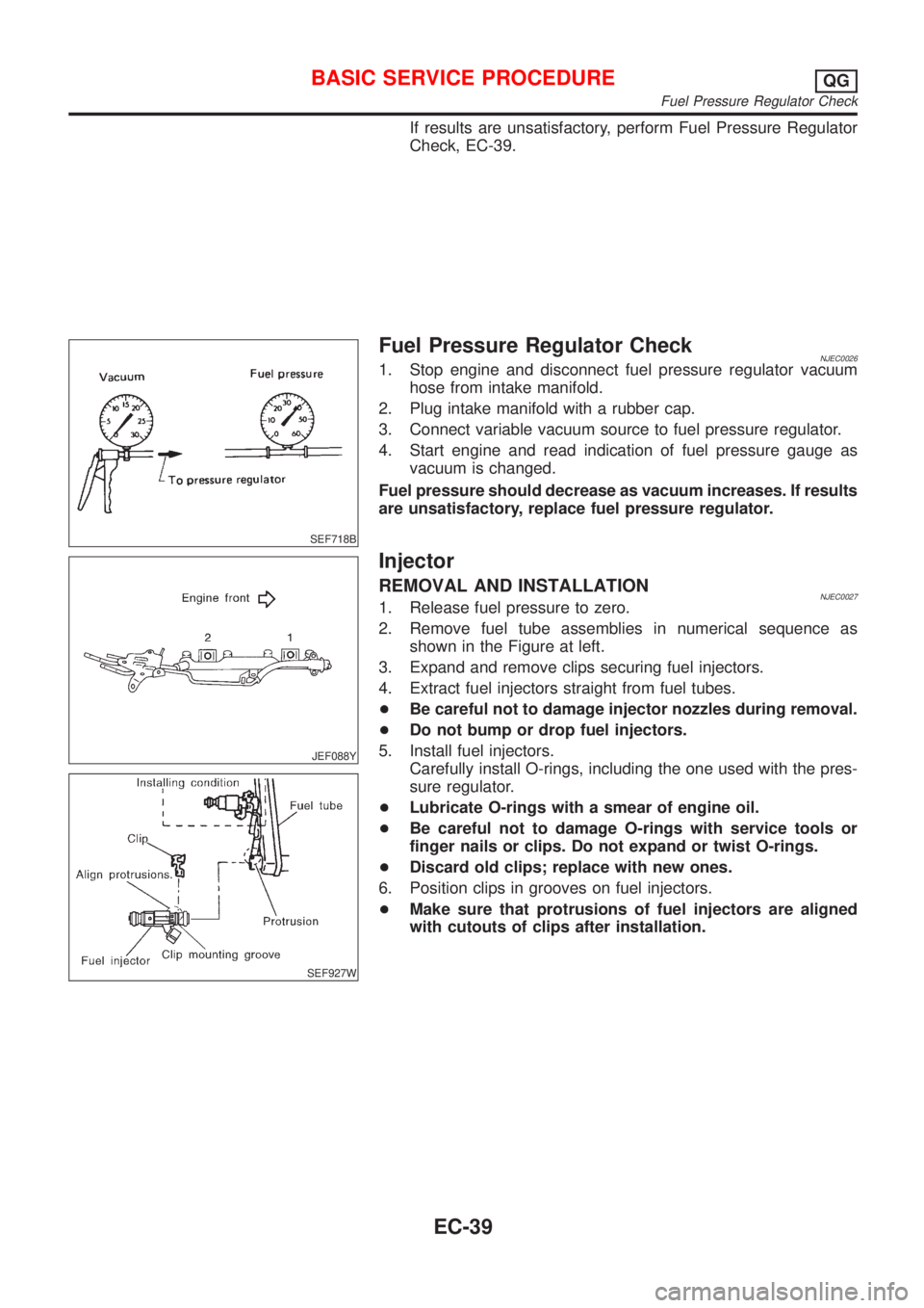
Fuel Pressure Regulator CheckNJEC00261. Stop engine and disconnect fuel pressure regulator vacuum
hose from intake manifold.
2. Plug intake manifold with a rubber cap.
3. Connect variable vacuum source to fuel pressure regulator.
4. Start engine and read indication of fuel pressure gauge as
vacuum is changed.
Fuel pressure should decrease as vacuum increases. If results
are unsatisfactory, replace fuel pressure regulator.
JEF088Y
SEF927W
Injector
REMOVAL AND INSTALLATIONNJEC00271. Release fuel pressure to zero.
2. Remove fuel tube assemblies in numerical sequence as
shown in the Figure at left.
3. Expand and remove clips securing fuel injectors.
4. Extract fuel injectors straight from fuel tubes.
+Be careful not to damage injector nozzles during removal.
+Do not bump or drop fuel injectors.
5. Install fuel injectors.
Carefully install O-rings, including the one used with the pres-
sure regulator.
+Lubricate O-rings with a smear of engine oil.
+Be careful not to damage O-rings with service tools or
finger nails or clips. Do not expand or twist O-rings.
+Discard old clips; replace with new ones.
6. Position clips in grooves on fuel injectors.
+Make sure that protrusions of fuel injectors are aligned
with cutouts of clips after installation.
BASIC SERVICE PROCEDUREQG
Fuel Pressure Regulator Check
EC-39
Page 336 of 2493
JEF089Y
7. Align protrusions of fuel tubes with those of fuel injectors.
Insert fuel injectors straight into fuel tubes.
8. After properly inserting fuel injectors, check to make sure that
fuel tube protrusions are engaged with those of fuel injectors,
and that flanges of fuel tubes are engaged with clips.
JEF815Y
9. Tighten fuel tube assembly mounting nuts in numerical
sequence (indicated in the Figure at left) and in two stages.
: Tightening torque N´m (kg-m, ft-lb)
1st stage:
12 - 13 (1.2 - 1.4, 9 - 10)
2nd stage:
17 - 23 (1.7 - 2.4, 13 - 17)
10. Insert fuel hoses into fuel tubes so that ends of fuel hoses butt
up against fuel tubes; fasten with clamps, avoiding bulges.
CAUTION:
After properly connecting fuel tube assembly to injector and
fuel hose, check connection for fuel leakage.
BASIC SERVICE PROCEDUREQG
Injector (Cont'd)
EC-40
Page 337 of 2493
SEF058Y
How to Check Idle Speed and Ignition TimingNJEC0028IDLE SPEEDNJEC0028S05Method A
+Using CONSULT-II
Check idle speed in ªDATA MONITORº mode with CONSULT-
II.
+With GST
Check idle speed in ªMODE 1º with GST.
SEF453Y
Method B (Using Loop wire)
Check the idle speed using loop-wire as shown in the figure.
JEF150Y
JEF438Z
IGNITION TIMINGNJEC0028S06Any of following two methods may be used.
+Method A
a) Attach timing light to loop wire or, combine the three No. 1
ignition coil harnesses and attach the timing light sensor
(attach from above the harness protector) as shown.
b) Check ignition timing.
BASIC SERVICE PROCEDUREQG
How to Check Idle Speed and Ignition Timing
EC-41
Page 338 of 2493
SEF933W
SEF284G
+Method B
a) Remove No. 1 ignition coil.
b) Connect No. 1 ignition coil and No. 1 spark plug with suitable
high-tension wire as shown, and attach timing light clamp to
this wire.
c) Check ignition timing.
SEF166Y
PreparationNJEC0592+Make sure that the following parts are in good order.
a)Battery
b)Ignition system
c)Engine oil and coolant levels
d)Fuses
e)ECM harness connector
f)Vacuum hoses
g)Air intake system
(Oil filler cap, oil level gauge, etc.)
BASIC SERVICE PROCEDUREQG
How to Check Idle Speed and Ignition Timing (Cont'd)
EC-42
Page 339 of 2493

h)Fuel pressure
i)Engine compression
j)EGR valve operation
k)Throttle valve
l)EVAP system
+On models equipped with air conditioner, checks should
be carried out while the air conditioner is ªOFFº.
+When checking idle speed on models equipped with A/T,
ignition timing and mixture ratio, checks should be carried
out while shift lever is in ªPº or ªNº position.
+When measuring ªCOº percentage, insert probe more
than 40 cm (15.7 in) into tail pipe.
+Turn off headlamps, heater blower, rear window defogger.
+On vehicles equipped with daytime light systems, set
lighting switch to the 1st position to light only small
lamps.
+Keep front wheels pointed straight ahead.
+If engine stops immediately after starting or idle condition
is unstable, perform the following to initialize IACV-AAC
valve:
a)Stop engine and wait 9 seconds.
b)Turn ignition ªONº and wait 1 second.
c)Turn ignition ªOFFº and wait 9 seconds.
+Make sure the cooling fan has stopped.
BASIC SERVICE PROCEDUREQG
Preparation (Cont'd)
EC-43