2001 NISSAN ALMERA N16 service
[x] Cancel search: servicePage 282 of 2493

Service Data and Specifications (SDS)
OIL PRESSURE CHECK=NJLC0048
Engine speed
rpmApproximate discharge pressure
kPa (bar, kg/cm2, psi)
Idle speed More than 140 (1.40, 1.43, 20.3)
2,000 More than 270 (2.69, 2.75, 39.1)
4,000 More than 430 (4.29, 4.38, 62.3)
REGULATOR VALVE INSPECTIONNJLC0049Unit: mm (in)
Regulator valve to oil pump cover clearance 0.040 - 0.097 (0.0016 - 0.0038)
OIL PUMP INSPECTIONNJLC0050Unit: mm (in)
Body to outer rotor radial clearance 0.114 - 0.260 (0.0045 - 0.0102)
Inner rotor to outer rotor tip clearance Below 0.18 (0.0071)
Body to inner rotor axial clearance 0.050 - 0.090 (0.0020 - 0.0035)
Body to outer rotor axial clearance 0.030 - 0.190 (0.0012 - 0.0075)
Inner rotor to brazed portion of housing clearance 0.045 - 0.091 (0.0018 - 0.0036)
ENGINE OIL CAPACITYNJLC0078Unit:!(Imp qt)
Drain and refill (Approximately)Without oil filter change 4.9 (4-3/8)
With oil filter change 5.2 (4-5/8)
Dry engine (engine overhaul)6.3 (5-1/2)
ENGINE LUBRICATION SYSTEMYD
Service Data and Specifications (SDS)
LC-34
Page 283 of 2493
SEM164F
AEM080
Precautions
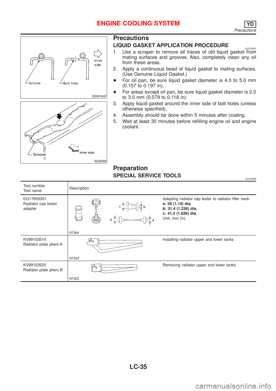
LIQUID GASKET APPLICATION PROCEDURENJLC00511. Use a scraper to remove all traces of old liquid gasket from
mating surfaces and grooves. Also, completely clean any oil
from these areas.
2. Apply a continuous bead of liquid gasket to mating surfaces.
(Use Genuine Liquid Gasket.)
+For oil pan, be sure liquid gasket diameter is 4.0 to 5.0 mm
(0.157 to 0.197 in).
+For areas except oil pan, be sure liquid gasket diameter is 2.0
to 3.0 mm (0.079 to 0.118 in).
3. Apply liquid gasket around the inner side of bolt holes (unless
otherwise specified).
4. Assembly should be done within 5 minutes after coating.
5. Wait at least 30 minutes before refilling engine oil and engine
coolant.
Preparation
SPECIAL SERVICE TOOLSNJLC0052
Tool number
Tool nameDescription
EG17650301
Radiator cap tester
adapter
NT564
Adapting radiator cap tester to radiator filler neck
a: 28 (1.10) dia.
b: 31.4 (1.236) dia.
c: 41.3 (1.626) dia.
Unit: mm (in)
KV99103510
Radiator plate pliers A
NT224
Installing radiator upper and lower tanks
KV99103520
Radiator plate pliers B
NT225
Removing radiator upper and lower tanks
ENGINE COOLING SYSTEMYD
Precautions
LC-35
Page 295 of 2493
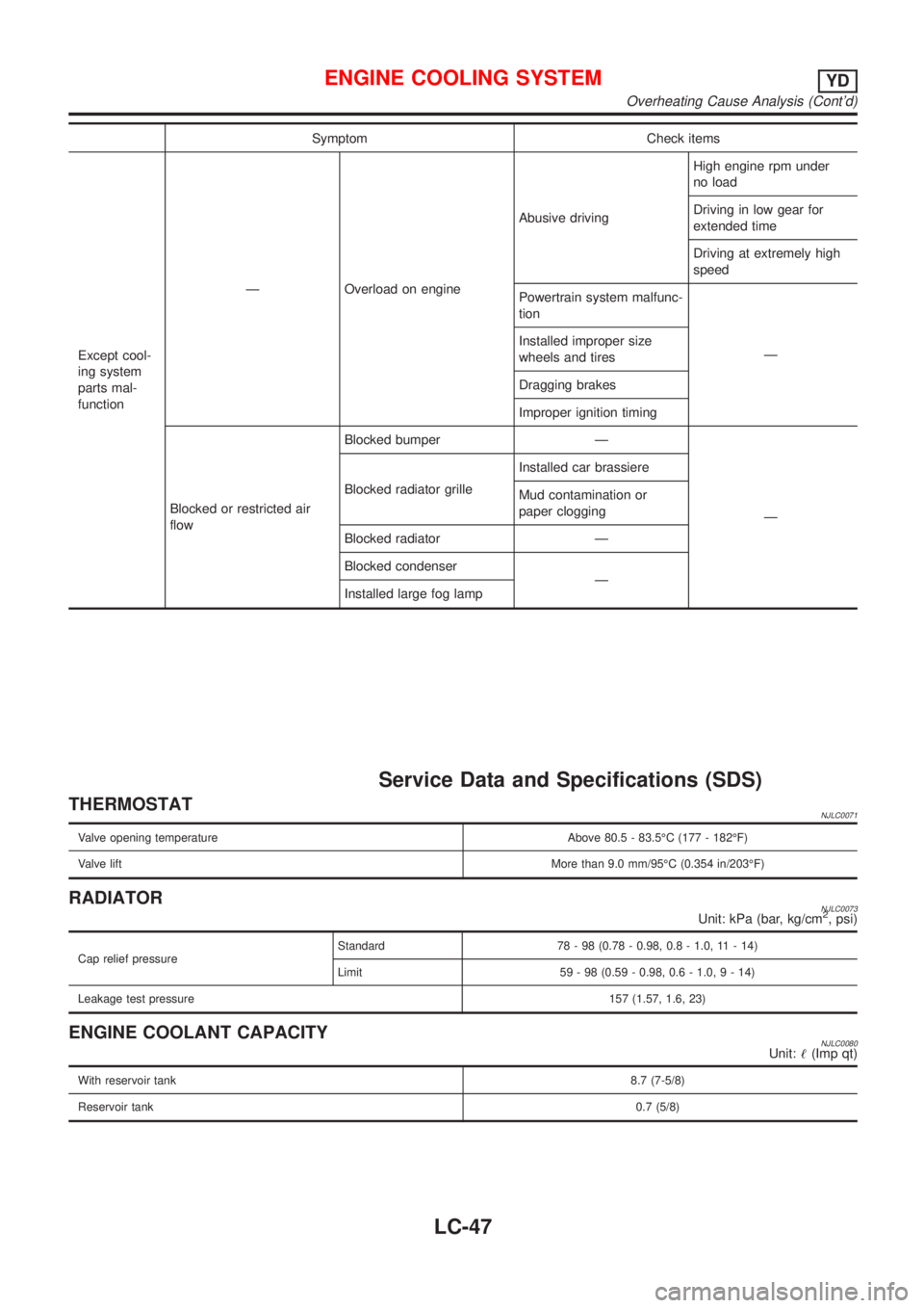
Symptom Check items
Except cool-
ing system
parts mal-
functionÐ Overload on engineAbusive drivingHigh engine rpm under
no load
Driving in low gear for
extended time
Driving at extremely high
speed
Powertrain system malfunc-
tion
Ð Installed improper size
wheels and tires
Dragging brakes
Improper ignition timing
Blocked or restricted air
flowBlocked bumper Ð
Ð Blocked radiator grilleInstalled car brassiere
Mud contamination or
paper clogging
Blocked radiator Ð
Blocked condenser
Ð
Installed large fog lamp
Service Data and Specifications (SDS)
THERMOSTATNJLC0071
Valve opening temperature Above 80.5 - 83.5ÉC (177 - 182ÉF)
Valve liftMore than 9.0 mm/95ÉC (0.354 in/203ÉF)
RADIATORNJLC0073Unit: kPa (bar, kg/cm2, psi)
Cap relief pressureStandard 78 - 98 (0.78 - 0.98, 0.8 - 1.0, 11 - 14)
Limit 59 - 98 (0.59 - 0.98, 0.6 - 1.0,9-14)
Leakage test pressure157 (1.57, 1.6, 23)
ENGINE COOLANT CAPACITYNJLC0080Unit:!(Imp qt)
With reservoir tank8.7 (7-5/8)
Reservoir tank0.7 (5/8)
ENGINE COOLING SYSTEMYD
Overheating Cause Analysis (Cont'd)
LC-47
Page 296 of 2493
ENGINE COOLING SYSTEM
Service Data and Specifications (SDS) (Cont'd)
LC-48
Page 297 of 2493
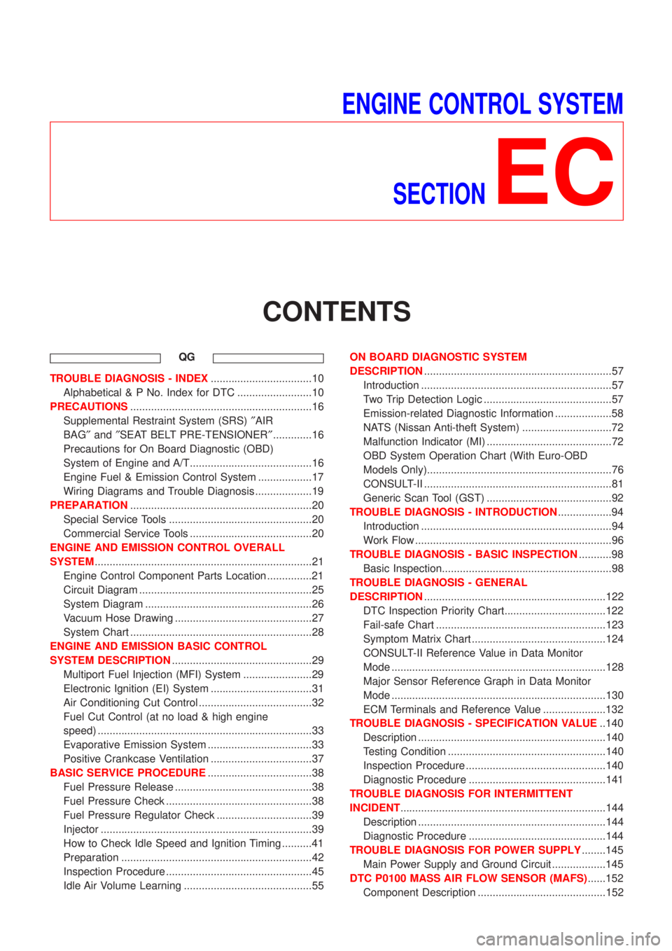
ENGINE CONTROL SYSTEM
SECTION
EC
CONTENTS
QG
TROUBLE DIAGNOSIS - INDEX..................................10
Alphabetical & P No. Index for DTC .........................10
PRECAUTIONS.............................................................16
Supplemental Restraint System (SRS)²AIR
BAG²and²SEAT BELT PRE-TENSIONER².............16
Precautions for On Board Diagnostic (OBD)
System of Engine and A/T.........................................16
Engine Fuel & Emission Control System ..................17
Wiring Diagrams and Trouble Diagnosis ...................19
PREPARATION.............................................................20
Special Service Tools ................................................20
Commercial Service Tools .........................................20
ENGINE AND EMISSION CONTROL OVERALL
SYSTEM.........................................................................21
Engine Control Component Parts Location ...............21
Circuit Diagram ..........................................................25
System Diagram ........................................................26
Vacuum Hose Drawing ..............................................27
System Chart .............................................................28
ENGINE AND EMISSION BASIC CONTROL
SYSTEM DESCRIPTION...............................................29
Multiport Fuel Injection (MFI) System .......................29
Electronic Ignition (EI) System ..................................31
Air Conditioning Cut Control ......................................32
Fuel Cut Control (at no load & high engine
speed) ........................................................................33
Evaporative Emission System ...................................33
Positive Crankcase Ventilation ..................................37
BASIC SERVICE PROCEDURE...................................38
Fuel Pressure Release ..............................................38
Fuel Pressure Check .................................................38
Fuel Pressure Regulator Check ................................39
Injector .......................................................................39
How to Check Idle Speed and Ignition Timing ..........41
Preparation ................................................................42
Inspection Procedure .................................................45
Idle Air Volume Learning ...........................................55ON BOARD DIAGNOSTIC SYSTEM
DESCRIPTION...............................................................57
Introduction ................................................................57
Two Trip Detection Logic ...........................................57
Emission-related Diagnostic Information ...................58
NATS (Nissan Anti-theft System) ..............................72
Malfunction Indicator (MI) ..........................................72
OBD System Operation Chart (With Euro-OBD
Models Only)..............................................................76
CONSULT-II ...............................................................81
Generic Scan Tool (GST) ..........................................92
TROUBLE DIAGNOSIS - INTRODUCTION..................94
Introduction ................................................................94
Work Flow ..................................................................96
TROUBLE DIAGNOSIS - BASIC INSPECTION...........98
Basic Inspection.........................................................98
TROUBLE DIAGNOSIS - GENERAL
DESCRIPTION.............................................................122
DTC Inspection Priority Chart..................................122
Fail-safe Chart .........................................................123
Symptom Matrix Chart .............................................124
CONSULT-II Reference Value in Data Monitor
Mode ........................................................................128
Major Sensor Reference Graph in Data Monitor
Mode ........................................................................130
ECM Terminals and Reference Value .....................132
TROUBLE DIAGNOSIS - SPECIFICATION VALUE..140
Description ...............................................................140
Testing Condition .....................................................140
Inspection Procedure ...............................................140
Diagnostic Procedure ..............................................141
TROUBLE DIAGNOSIS FOR INTERMITTENT
INCIDENT.....................................................................144
Description ...............................................................144
Diagnostic Procedure ..............................................144
TROUBLE DIAGNOSIS FOR POWER SUPPLY........145
Main Power Supply and Ground Circuit ..................145
DTC P0100 MASS AIR FLOW SENSOR (MAFS)......152
Component Description ...........................................152
Page 302 of 2493
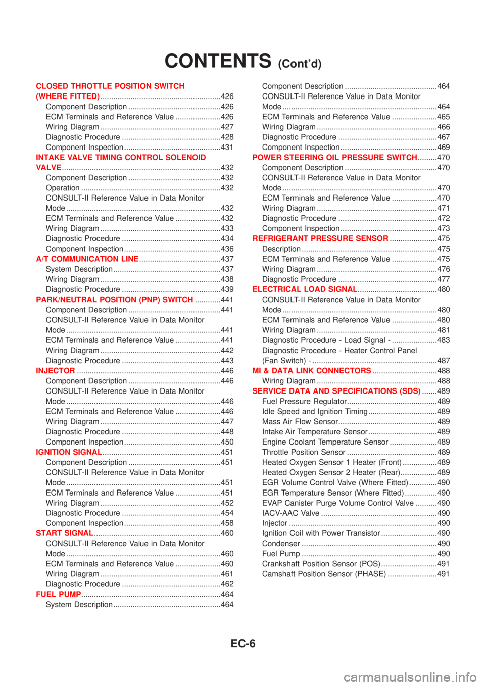
CLOSED THROTTLE POSITION SWITCH
(WHERE FITTED)........................................................426
Component Description ...........................................426
ECM Terminals and Reference Value .....................426
Wiring Diagram ........................................................427
Diagnostic Procedure ..............................................428
Component Inspection .............................................431
INTAKE VALVE TIMING CONTROL SOLENOID
VALVE..........................................................................432
Component Description ...........................................432
Operation .................................................................432
CONSULT-II Reference Value in Data Monitor
Mode ........................................................................432
ECM Terminals and Reference Value .....................432
Wiring Diagram ........................................................433
Diagnostic Procedure ..............................................434
Component Inspection .............................................436
A/T COMMUNICATION LINE......................................437
System Description ..................................................437
Wiring Diagram ........................................................438
Diagnostic Procedure ..............................................439
PARK/NEUTRAL POSITION (PNP) SWITCH............441
Component Description ...........................................441
CONSULT-II Reference Value in Data Monitor
Mode ........................................................................441
ECM Terminals and Reference Value .....................441
Wiring Diagram ........................................................442
Diagnostic Procedure ..............................................443
INJECTOR...................................................................446
Component Description ...........................................446
CONSULT-II Reference Value in Data Monitor
Mode ........................................................................446
ECM Terminals and Reference Value .....................446
Wiring Diagram ........................................................447
Diagnostic Procedure ..............................................448
Component Inspection .............................................450
IGNITION SIGNAL.......................................................451
Component Description ...........................................451
CONSULT-II Reference Value in Data Monitor
Mode ........................................................................451
ECM Terminals and Reference Value .....................451
Wiring Diagram ........................................................452
Diagnostic Procedure ..............................................454
Component Inspection .............................................458
START SIGNAL...........................................................460
CONSULT-II Reference Value in Data Monitor
Mode ........................................................................460
ECM Terminals and Reference Value .....................460
Wiring Diagram ........................................................461
Diagnostic Procedure ..............................................462
FUEL PUMP.................................................................464
System Description ..................................................464Component Description ...........................................464
CONSULT-II Reference Value in Data Monitor
Mode ........................................................................464
ECM Terminals and Reference Value .....................465
Wiring Diagram ........................................................466
Diagnostic Procedure ..............................................467
Component Inspection .............................................469
POWER STEERING OIL PRESSURE SWITCH.........470
Component Description ...........................................470
CONSULT-II Reference Value in Data Monitor
Mode ........................................................................470
ECM Terminals and Reference Value .....................470
Wiring Diagram ........................................................471
Diagnostic Procedure ..............................................472
Component Inspection .............................................473
REFRIGERANT PRESSURE SENSOR......................475
Description ...............................................................475
ECM Terminals and Reference Value .....................475
Wiring Diagram ........................................................476
Diagnostic Procedure ..............................................477
ELECTRICAL LOAD SIGNAL.....................................480
CONSULT-II Reference Value in Data Monitor
Mode ........................................................................480
ECM Terminals and Reference Value .....................480
Wiring Diagram ........................................................481
Diagnostic Procedure - Load Signal - .....................483
Diagnostic Procedure - Heater Control Panel
(Fan Switch) - ..........................................................487
MI & DATA LINK CONNECTORS..............................488
Wiring Diagram ........................................................488
SERVICE DATA AND SPECIFICATIONS (SDS).......489
Fuel Pressure Regulator..........................................489
Idle Speed and Ignition Timing ................................489
Mass Air Flow Sensor..............................................489
Intake Air Temperature Sensor ................................489
Engine Coolant Temperature Sensor ......................489
Throttle Position Sensor ..........................................489
Heated Oxygen Sensor 1 Heater (Front) ................489
Heated Oxygen Sensor 2 Heater (Rear).................489
EGR Volume Control Valve (Where Fitted) .............490
EGR Temperature Sensor (Where Fitted) ...............490
EVAP Canister Purge Volume Control Valve ..........490
IACV-AAC Valve ......................................................490
Injector .....................................................................490
Ignition Coil with Power Transistor ..........................490
Condenser ...............................................................490
Fuel Pump ...............................................................490
Crankshaft Position Sensor (POS) ..........................491
Camshaft Position Sensor (PHASE) .......................491
CONTENTS(Cont'd)
EC-6
Page 303 of 2493

YD
TROUBLE DIAGNOSIS - INDEX................................492
Alphabetical & P No. Index for DTC .......................492
PRECAUTIONS...........................................................494
Supplemental Restraint System (SRS)²AIR
BAG²and²SEAT BELT PRE-TENSIONER²...........494
Engine Fuel & Emission Control System ................495
Precautions ..............................................................496
Wiring Diagrams and Trouble Diagnosis .................497
PREPARATION...........................................................498
Special Service Tools ..............................................498
ENGINE AND EMISSION CONTROL OVERALL
SYSTEM.......................................................................499
Engine Control Component Parts Location .............499
Circuit Diagram ........................................................502
System Diagram ......................................................503
System Chart ...........................................................504
ENGINE AND EMISSION BASIC CONTROL
SYSTEM DESCRIPTION.............................................505
Fuel Injection Control System .................................505
Fuel Injection Timing Control System......................506
Air Conditioning Cut Control ....................................507
Fuel Cut Control (at no load & high engine
speed) ......................................................................507
Crankcase Ventilation System .................................508
BASIC SERVICE PROCEDURE.................................509
Injection Tube and Injection Nozzle ........................509
Electronic Control Fuel Injection Pump ...................513
Fuel Filter .................................................................520
ON BOARD DIAGNOSTIC SYSTEM
DESCRIPTION.............................................................522
DTC and MI Detection Logic ...................................522
Diagnostic Trouble Code (DTC) ..............................522
Malfunction Indicator (MI) ........................................523
CONSULT-II .............................................................527
TROUBLE DIAGNOSIS - INTRODUCTION................532
Introduction ..............................................................532
Work Flow ................................................................534
TROUBLE DIAGNOSIS - BASIC INSPECTION.........536
Basic Inspection.......................................................536
TROUBLE DIAGNOSIS - GENERAL
DESCRIPTION.............................................................541
Symptom Matrix Chart .............................................541
CONSULT-II Reference Value in Data Monitor
Mode ........................................................................551
Major Sensor Reference Graph in Data Monitor
Mode ........................................................................553
ECM Terminals and Reference Value .....................554
TROUBLE DIAGNOSIS FOR INTERMITTENT
INCIDENT.....................................................................559
Description ...............................................................559
Diagnostic Procedure ..............................................559TROUBLE DIAGNOSIS FOR POWER SUPPLY........560
Main Power Supply and Ground Circuit ..................560
DTC P0100 MASS AIR FLOW SEN...........................566
Component Description ...........................................566
CONSULT-II Reference Value in Data Monitor
Mode ........................................................................566
ECM Terminals and Reference Value .....................566
On Board Diagnosis Logic.......................................566
DTC Confirmation Procedure ..................................566
Wiring Diagram ........................................................568
Diagnostic Procedure ..............................................569
DTC P0115 COOLANT TEMP SEN............................572
Description ...............................................................572
On Board Diagnosis Logic.......................................572
DTC Confirmation Procedure ..................................572
Wiring Diagram ........................................................574
Diagnostic Procedure ..............................................575
DTC P0120 ACCEL POS SENSOR............................577
Description ...............................................................577
CONSULT-II Reference Value in Data Monitor
Mode ........................................................................577
ECM Terminals and Reference Value .....................577
On Board Diagnosis Logic.......................................578
DTC Confirmation Procedure ..................................578
Wiring Diagram ........................................................579
Diagnostic Procedure ..............................................580
DTC P0335 CRANK POS SEN (TDC)........................587
Description ...............................................................587
CONSULT-II Reference Value in Data Monitor
Mode ........................................................................587
ECM Terminals and Reference Value .....................587
On Board Diagnosis Logic.......................................587
DTC Confirmation Procedure ..................................588
Wiring Diagram ........................................................589
Diagnostic Procedure ..............................................590
DTC P0500 VEHICLE SPEED SEN............................593
Description ...............................................................593
ECM Terminals and Reference Value .....................593
On Board Diagnosis Logic.......................................593
Overall Function Check ...........................................593
Wiring Diagram ........................................................595
Diagnostic Procedure ..............................................596
DTC P0571 BRAKE SW..............................................597
Description ...............................................................597
ECM Terminals and Reference Value .....................597
On Board Diagnosis Logic.......................................597
DTC Confirmation Procedure ..................................597
Wiring Diagram ........................................................599
Diagnostic Procedure ..............................................600
DTC P1107 ECM 10....................................................604
Description ...............................................................604
On Board Diagnosis Logic.......................................604
CONTENTS(Cont'd)
EC-7
Page 305 of 2493
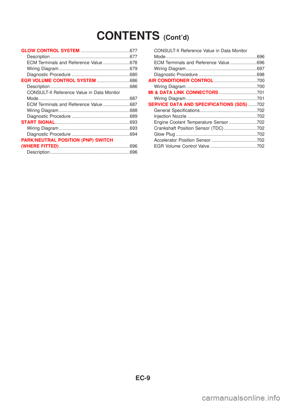
GLOW CONTROL SYSTEM.......................................677
Description ...............................................................677
ECM Terminals and Reference Value .....................678
Wiring Diagram ........................................................679
Diagnostic Procedure ..............................................680
EGR VOLUME CONTROL SYSTEM..........................686
Description ...............................................................686
CONSULT-II Reference Value in Data Monitor
Mode ........................................................................687
ECM Terminals and Reference Value .....................687
Wiring Diagram ........................................................688
Diagnostic Procedure ..............................................689
START SIGNAL...........................................................693
Wiring Diagram ........................................................693
Diagnostic Procedure ..............................................694
PARK/NEUTRAL POSITION (PNP) SWITCH
(WHERE FITTED)........................................................696
Description ...............................................................696CONSULT-II Reference Value in Data Monitor
Mode ........................................................................696
ECM Terminals and Reference Value .....................696
Wiring Diagram ........................................................697
Diagnostic Procedure ..............................................698
AIR CONDITIONER CONTROL..................................700
Wiring Diagram ........................................................700
MI & DATA LINK CONNECTORS..............................701
Wiring Diagram ........................................................701
SERVICE DATA AND SPECIFICATIONS (SDS).......702
General Specifications .............................................702
Injection Nozzle .......................................................702
Engine Coolant Temperature Sensor ......................702
Crankshaft Position Sensor (TDC) ..........................702
Glow Plug ................................................................702
Accelerator Position Sensor ....................................702
EGR Volume Control Valve .....................................702
CONTENTS(Cont'd)
EC-9