Page 137 of 224

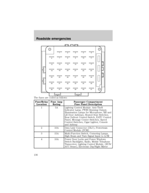
Fuse/Relay
LocationFuse Amp
RatingPassenger Compartment
Fuse Panel Description
5 10A Virtual Image Instrument Cluster, Lighting
Control Module (LCM RUN/START Sense),
Autolamp Light Sensor
6 10A Virtual Image Instrument Cluster, RF
Park/Turn Lamp
7 20A Power Point
8 20A Fuel Filler Door Release Switch, Trunk Lid
Relay
9 10A Air Bag Diagnostic Monitor, EATC Module,
Blower Motor Relay
10 30A Windshield Wiper Motor, Windshield Wiper
Module
11 10A Ignition Coils, Radio Interference Capacitor,
PCM Power Relay, Passive Anti-Theft
System (PATS) Transceiver
12 10A Lighting Control Module
13 15A Lighting Control Module (LCM): RF Turn
Lamp, Right Turn Indicator (VIC), RR Side
Marker Lamps, Tail Lamps, License Lamps,
LR Stop/Turn Lamps, Clock Illumination
14 20A Cigar Lighter
15 10A ABS Evac and Fill Connector
16 30A Moonroof Switch
17 Ð Not Used
18 10A Lighting Control Module
19 10A Lighting Control Module (LCM): Left
Headlamp, DRL
20 15A Multi-Function Switch: Flash to Pass, and
Hazard Warning Input to LCM
21 Ð Not Used
22 Ð Not Used
23 10A Digital Transmission Range Sensor
24 10A Virtual Image Cluster-LF Turn Indicator, LF
Turn Signal
Roadside emergencies
137
Page 138 of 224

Fuse/Relay
LocationFuse Amp
RatingPassenger Compartment
Fuse Panel Description
25 10A Lighting Control Module (LCM): Right
Headlamp
26 10A Virtual Image Instrument Cluster, EATC
Module
27 Ð Not Used
28 10A Shift Lock Actuator, Vehicle Dynamic
Module, Virtual Image Instrument Cluster,
Rear Window Defrost, Heated Seat Switch
Assembly, Low Tire Pressure Module
29 10A Radio
30 10A Heated Mirrors
31 15A Lighting Control Module (LCM): FCU,
Electronic Day/Night Mirror, RH and LH
Courtesy Lamp, Door Courtesy Lamps, RH
and LH Map Lamps, RR and LR Reading
Lamps, RH and LH Visor Lamps, Storage
Bin Lamps, Trunk Lid Lamp, Glove Box
Lamp, Light Sensor Amplifier
32 15A Speed Control DEAC. Switch, Brake On/Off
(BOO) Switch
33 Ð Not Used
34 15A Console Shift Illumination, A/C Clutch
Cycling Pressure Switch, A/C Clutch Relay
(DTR) Sensor, Intake Manifold Runner
Control, Backup Lamps
35 Ð Not Used
36 Ð Not Used
37 30A Subwoofer Amplifier, Radio
38 10A Analog Clock, CD Player, Mobile Telephone
Transceiver, RESCU
39 10A Power Door Locks, Power Seats, Power
Mirrors, Keyless Entry, LF Seat Module, LF
Door Module
40 10A Cornering Lamps
41 20A Door Locks
Roadside emergencies
138
Page 139 of 224
Power distribution box
The power distribution box is located in the engine compartment. The
power distribution box contains high-current fuses that protect your
vehicle's main electrical systems from overloads.
Always disconnect the battery before servicing high current
fuses.
Always replace the cover to the Power Distribution Box before
reconnecting the battery or refilling fluid reservoirs.
If the battery has been disconnected and reconnected, refer to the
Batterysection of theMaintenance and carechapter.
The high-current fuses are coded as follows:
Fuse/Relay
LocationFuse Amp
RatingPower Distribution Box Description
1 Ð A/C Diode
2 Ð PCM Diode
1 30A* PCM
2 20A* ALT SENSE
3 30A* Right Rear Passenger Window
4 30A* Air Suspension
5 Ð Not Used
6 20A* Horns
MEGA
175A
PCM
PWR
RELAY
12 3 4
8
7
6 5
12
4 3
5
7
9
1110
12
14 136
8NOT USED
7BLOWER
MOTOR
RELAY6A/C
CLUTCH
RELAY4NOT
USED2
HORN
RELAY3HIGH
BEAM1STARTER
SOL
RELAY5
12
Roadside emergencies
139
Page 140 of 224

Fuse/Relay
LocationFuse Amp
RatingPower Distribution Box Description
7 15A* High Beam
8 30A* Right Front Passenger Window
1 30A** Driver's Seat Module
2 30A** Passenger's Seat Module
3 40A** Ignition Switch
4 40A** Ignition Switch
5 40A** Driver Window
6 30A** Low Speed Cooling Fan
7 30A** Powertrain Control Module
8 40A** Rear Window Defrost Control
9 60A** I/P Fuse Panel
10 60A** Lighting Control Module
11 60A** Compressor Relay
12 60A** Anti-Lock Brake Control Module
13 40A** Blower Motor
14 60A** High Speed Cooling Fan
Ð 175 Generator/Voltage Regulator
* Mini Fuses ** Maxi Fuses
Auxiliary relay box
The auxiliary relay box is located in the engine compartment. The
auxiliary relay box contains the high and low speed cooling fan relays.
CHANGING THE TIRES
If you get a flat tire while driving, do not apply the brake heavily.
Instead, gradually decrease your speed. Hold the steering wheel firmly
and slowly move to a safe place on the side of the road.
Roadside emergencies
140
Page 141 of 224
Tire change procedure
To prevent the vehicle from moving when you change a tire, be
sure the parking brake is set, then block (in both directions) the
wheel that is diagonally opposite (other side and end of the vehicle) to
the tire being changed.
If the vehicle slips off the jack, you or someone else could be
seriously injured.
1. Park on a level surface, activate hazard flashers and set parking brake.
2. Place gearshift lever in P (Park) and turn engine OFF.
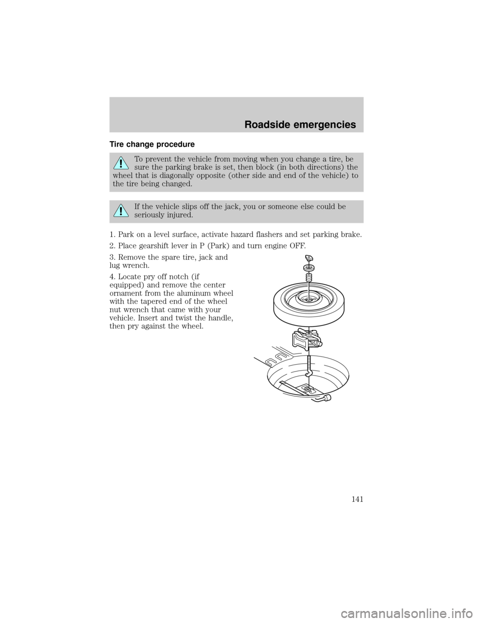
3. Remove the spare tire, jack and
lug wrench.
4. Locate pry off notch (if
equipped) and remove the center
ornament from the aluminum wheel
with the tapered end of the wheel
nut wrench that came with your
vehicle. Insert and twist the handle,
then pry against the wheel.
Roadside emergencies
141
Page 142 of 224
5. Loosen each wheel lug nut
one-half turn counterclockwise but
do not remove them until the wheel
is raised off the ground. Refer to
Anti-theft lug nutsfor information
on removing anti-theft lug nuts.
On vehicles equipped with
Air Suspension, turn OFF
the Air Suspension switch prior to
jacking, hoisting or towing your
vehicle.
Refer toAir suspension systemin
theDrivingchapter for more
information.
6. Put the jack in the jack notch
next to the door closest to the tire
you are changing. Turn the jack
handle clockwise until the wheel is
completely off the ground.
OFF
Roadside emergencies
142
Page 143 of 224

To lessen the risk of personal injury, do not put any part of your
body under the vehicle while changing a tire. Do not start the
engine when your vehicle is on the jack. The jack is only meant for
changing the tire.
7. Remove the lug nuts with the lug wrench. Replace the flat tire with
the spare tire, making sure the valve stem is facing outward. Reinstall lug
nuts until the wheel is snug against the hub. Do not fully tighten the lug
nuts until the wheel has been lowered.
8. Lower the wheel by turning the jack handle counterclockwise.
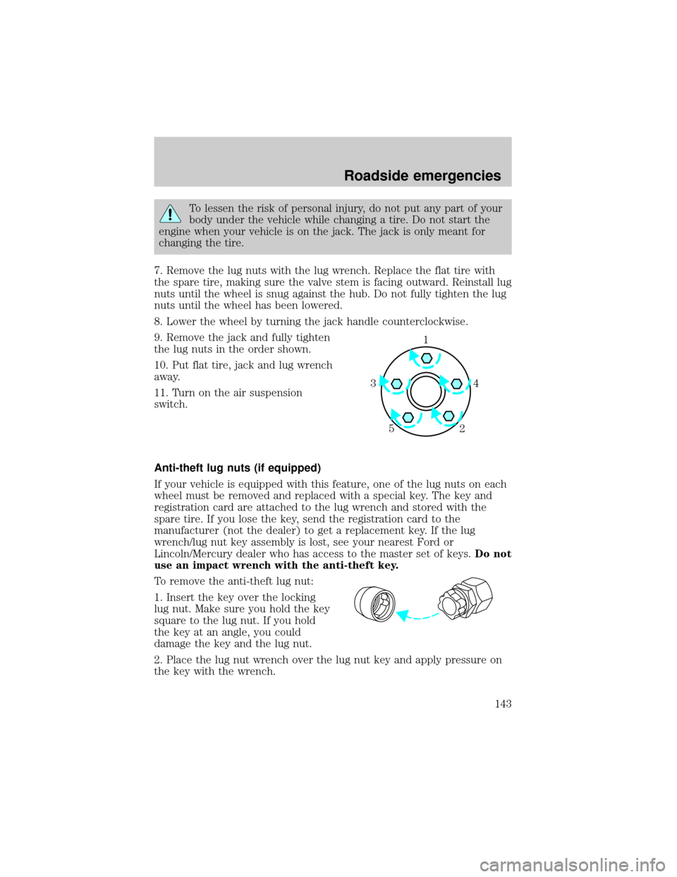
9. Remove the jack and fully tighten
the lug nuts in the order shown.
10. Put flat tire, jack and lug wrench
away.
11. Turn on the air suspension
switch.
Anti-theft lug nuts (if equipped)
If your vehicle is equipped with this feature, one of the lug nuts on each
wheel must be removed and replaced with a special key. The key and
registration card are attached to the lug wrench and stored with the
spare tire. If you lose the key, send the registration card to the
manufacturer (not the dealer) to get a replacement key. If the lug
wrench/lug nut key assembly is lost, see your nearest Ford or
Lincoln/Mercury dealer who has access to the master set of keys.Do not
use an impact wrench with the anti-theft key.
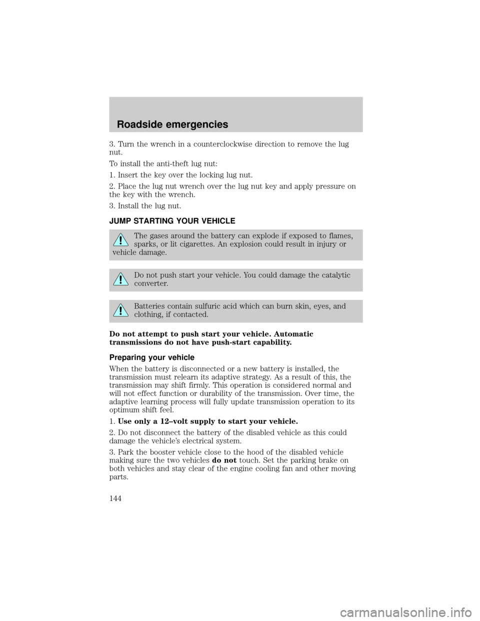
To remove the anti-theft lug nut:
1. Insert the key over the locking
lug nut. Make sure you hold the key
square to the lug nut. If you hold
the key at an angle, you could
damage the key and the lug nut.
2. Place the lug nut wrench over the lug nut key and apply pressure on
the key with the wrench.
1
4 3
2 5
Roadside emergencies
143
Page 144 of 224

3. Turn the wrench in a counterclockwise direction to remove the lug
nut.
To install the anti-theft lug nut:
1. Insert the key over the locking lug nut.
2. Place the lug nut wrench over the lug nut key and apply pressure on
the key with the wrench.
3. Install the lug nut.
JUMP STARTING YOUR VEHICLE
The gases around the battery can explode if exposed to flames,
sparks, or lit cigarettes. An explosion could result in injury or
vehicle damage.
Do not push start your vehicle. You could damage the catalytic
converter.
Batteries contain sulfuric acid which can burn skin, eyes, and
clothing, if contacted.
Do not attempt to push start your vehicle. Automatic
transmissions do not have push-start capability.
Preparing your vehicle
When the battery is disconnected or a new battery is installed, the
transmission must relearn its adaptive strategy. As a result of this, the
transmission may shift firmly. This operation is considered normal and
will not effect function or durability of the transmission. Over time, the
adaptive learning process will fully update transmission operation to its
optimum shift feel.
1.Use only a 12±volt supply to start your vehicle.
2. Do not disconnect the battery of the disabled vehicle as this could
damage the vehicle's electrical system.
3. Park the booster vehicle close to the hood of the disabled vehicle
making sure the two vehiclesdo nottouch. Set the parking brake on
both vehicles and stay clear of the engine cooling fan and other moving
parts.
Roadside emergencies
144