2001 LAND ROVER FREELANDER airbag
[x] Cancel search: airbagPage 57 of 1007

GENERAL INFORMATION
03-26
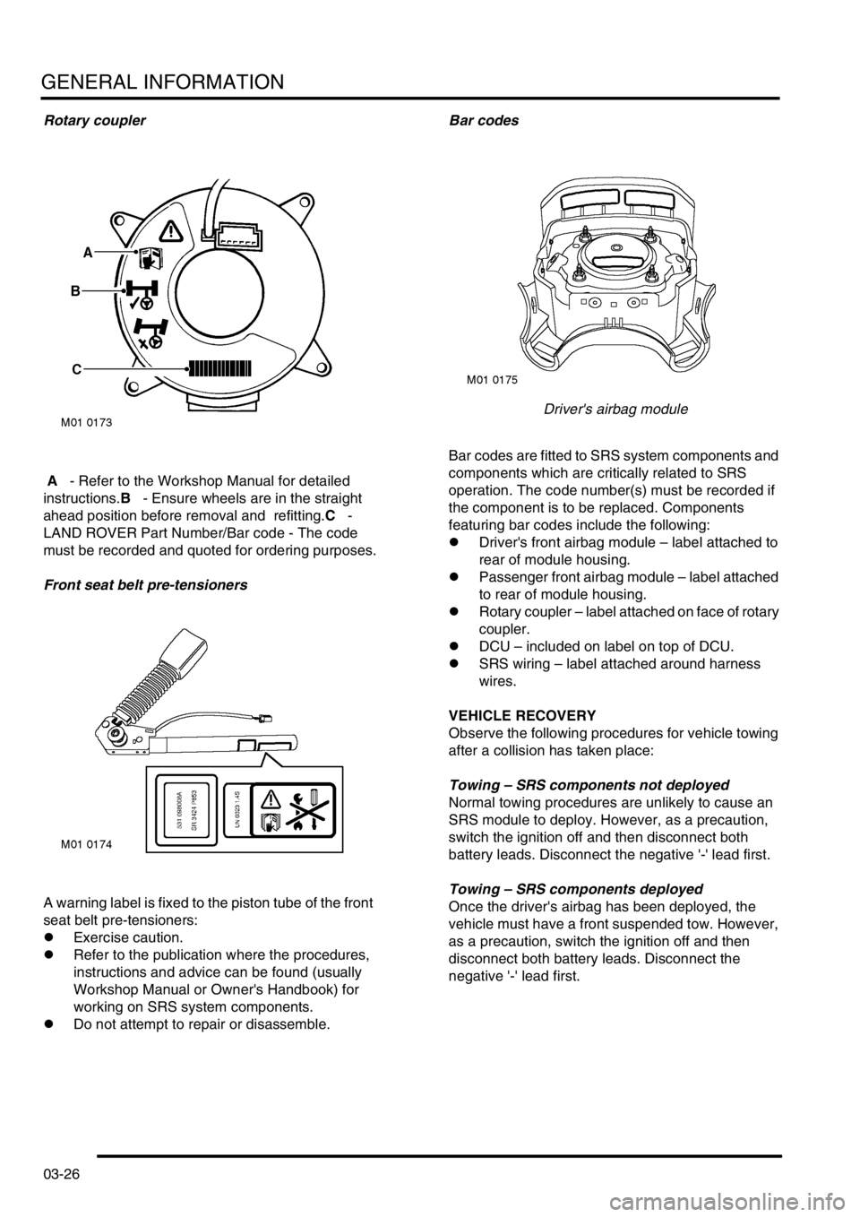
Rotary coupler
A - Refer to the Workshop Manual for detailed
instructions.B - Ensure wheels are in the straight
ahead position before removal and refitting.C -
LAND ROVER Part Number/Bar code - The code
must be recorded and quoted for ordering purposes.
Front seat belt pre-tensioners
A warning label is fixed to the piston tube of the front
seat belt pre-tensioners:
lExercise caution.
lRefer to the publication where the procedures,
instructions and advice can be found (usually
Workshop Manual or Owner's Handbook) for
working on SRS system components.
lDo not attempt to repair or disassemble.Bar codes
Driver's airbag module
Bar codes are fitted to SRS system components and
components which are critically related to SRS
operation. The code number(s) must be recorded if
the component is to be replaced. Components
featuring bar codes include the following:
lDriver's front airbag module – label attached to
rear of module housing.
lPassenger front airbag module – label attached
to rear of module housing.
lRotary coupler – label attached on face of rotary
coupler.
lDCU – included on label on top of DCU.
lSRS wiring – label attached around harness
wires.
VEHICLE RECOVERY
Observe the following procedures for vehicle towing
after a collision has taken place:
Towing – SRS components not deployed
Normal towing procedures are unlikely to cause an
SRS module to deploy. However, as a precaution,
switch the ignition off and then disconnect both
battery leads. Disconnect the negative '-' lead first.
Towing – SRS components deployed
Once the driver's airbag has been deployed, the
vehicle must have a front suspended tow. However,
as a precaution, switch the ignition off and then
disconnect both battery leads. Disconnect the
negative '-' lead first.
Page 58 of 1007

GENERAL INFORMATION
03-27
SRS component manual deployment
If a vehicle is to be scrapped and contains an
undeployed airbag module, the module must be
manually deployed. Always observe the following
precautions:
WARNING: Only personnel who have undergone
the appropriate training should undertake
deployment of airbag and seat belt pre-tensioner
modules.
WARNING: A deployed airbag or seatbelt pre-
tensioner is very hot, DO NOT return to a
deployed airbag module until at least 30 minutes
have elapsed since deployment.
WARNING: Only use approved deployment
equipment, and only deploy SRS components in
a well ventilated designated area. Ensure SRS
components are not damaged or ruptured before
deployment. Notify the relevant authorities.
WARNING: If a vehicle is to be scrapped,
undeployed airbag modules and pre-tensioner
units must be deployed in accordance with the
instructions in this manual.
WARNING: Contact with chemicals from
deployed and damaged SRS components could
present a health hazard, wear protective clothing
when handling. DO NOT eat, drink or smoke
when handling SRS components.
WARNING: Deployment of airbag modules and
seatbelt pre-tensioners can cause injury to
personnel in the close vicinity of the deploying
unit. In case of injury seek urgent medical advice.
Possible sources of injury include:
limpact - due to inflating airbag or pre-
tensioner operation causing component
'kick'.
l hearing - due to noise produced by
deploying airbags and seatbelt pre-
tensioner units.
l burns - hot component parts and gases.
l irritation to eyes and lungs - from deploying
gases or combustion residue.
WARNING: Ensure the SRS component to be
deployed is securely fastened to its mounting.WARNING: Deployment procedures detailed in
this manual should be strictly adhered to.
Compliance with the following precautions
MUST be ensured:
lOnly use deployment equipment approved
for the intended purpose.
lBefore commencing deployment procedure,
ensure the deployment tool functions
properly by performing the self test
procedure detailed in the SRS Repairs
section of this manual.
lDeployment of airbag/pre-tensioner
modules should be performed in a well
ventilated area which has been designated
for the purpose.
lEnsure airbag/pre-tensioner modules are
not damaged or ruptured before attempting
to deploy.
lNotify the relevant authorities of intention to
deploy airbag and pre-tensioner units.
lWhen deploying airbag and seatbelt pre-
tensioner units, ensure that all personnel are
at least 15 metres away from the deployment
zone.
lEnsure deployment tool is connected
correctly, in compliance with the
instructions detailed in this manual. In
particular, ensure deployment tool is NOT
connected to battery supply before
connecting to the airbag or seatbelt pre-
tensioner module connector.
lWhen deploying seatbelt pre-tensioners in
the vehicle, ensure the pre-tensioner unit is
fully secured to its fixing point.
lWhen removing deployed airbag and
seatbelt pre-tensioner modules, wear
protective clothing. Use gloves and seal
deployed units in a plastic bag.
lFollowing deployment of any component of
the SRS system within the vehicle, all SRS
components must be replaced. DO NOT re-
use or salvage any parts of the SRS system.
lDo not lean over airbag modules or seatbelt
pre-tensioner units when connecting
deployment equipment.
WARNING: During deployment parts of the
airbag module become hot enough to burn you.
Wait 30 minutes after deployment before
touching the airbag module.
Page 59 of 1007

GENERAL INFORMATION
03-28
SRS component replacement policy
The following information details the policy for
replacement of SRS components; either as a result
of a vehicle accident or as a result of vehicle age.
Impacts which do not deploy the airbags or seat
belt pre-tensioners
Check for structural damage in the area of the
impact, paying particular attention to bumper
armatures, longitudinals, crash cans and bracketry.
Impacts which deploy the airbags and/or seat
belt pre-tensioners
The inspection and replacement policy is dependent
on the type and severity of the crash condition. The
following guidelines are the minimum that should be
exercised as a result of the deployment of specific
SRS components.
Front airbag/ seat belt pre-tensioner deployment
(driver and passenger)
If the front airbags and/or seat belt pre-tensioners are
deployed as a result of a front, front angled or side
impact, the following parts must be replaced:
lDriver airbag module
lPassenger airbag module (where fitted)
lSRS flyleads
lSRS DCU
lRotary coupler
lFront seat belt pre-tensioners
In addition, the following should be inspected for
damage and replaced as necessary:
lFront seat belt and buckle tongue (anchorage
points, webbing etc.)
lFascia moulding adjacent to passenger airbag
module (where fitted)
lSteering wheel (if damage is evident)
lFront seat frames and head restraints (if there is
evidence of damage to the seat frame or
cushion pan)
lSteering column (if adjustment is lost or there
are signs of collapse)
lFront seat belt height adjusters on 'BC' posts (5
door models only)
lRear seat belts and seat belt buckles (webbing,
buckle covers, body anchorage and tongue
latching function)Rear Impact
If the seat belt pre-tensioners are deployed during a
rear impact, the following components must be
replaced:
lSeat belt pre-tensioners
lFront and rear automatic seat belt assemblies
used during an impact.
lSRS DCU
In addition, the following components should be
inspected for damage and replaced as necessary:
lFront seat frames
lFront seat belts and buckle (retractors,
webbing, tongue latching, buckle covers, body
anchorages and 'D' loops)
lSeat belt height adjusters (5 door models only)
lRear seat belts and seat belt buckles (webbing,
buckle covers, body anchorage and tongue
latching function)
Periodic replacement of SRS components
The performance of the propellants within airbags
and seat belt pre-tensioners will deteriorate over a
period of time. As a result, it is essential that the
airbags and seat belt pre-tensioners are periodically
replaced to maintain occupant safety. Airbags, seat
belt pre-tensioners and the rotary coupler should be
replaced at the recommended intervals.
Page 132 of 1007

TORQUE WRENCH SETTINGS
06-29
Supplementary Restraint Systems
TORQUE DESCRIPTION METRIC IMPERIAL
SRS Diagnostic Control Unit (DCU) fixing bolts 9 Nm 6.5 lbf.ft
Driver's airbag module to steering wheel Torx screws 9 Nm 6.5 lbf.ft
Front seat belt pre-tensioner to seat Torx bolt 32 Nm 24 lbf.ft
Passenger's airbag module to fascia Torx screws 9 Nm 6.5 lbf.ft
Page 363 of 1007

FUEL DELIVERY SYSTEM - PETROL
19-2-42 REPAIRS
Switch - engagement (on/off) - from
04MY
$% 19.75.30
Remove
1.Release 2 clips and remove fascia mounted
switch cover.
2.Remove 2 screws securing switch carrier to
fascia.
3.Release switch carrier from fascia and
disconnect switch multiplug.
4.Remove switch assembly from carrier.
Refit
1.Fit switch to carrier.
2.Connect multiplug to switch.
3.Secure switch carrier to fascia with screws.
4.Fit and secure switch cover.
Switch - multi-purpose
$% 19.75.33
Remove
1.Remove airbag module from steering wheel.
+ RESTRAINT SYSTEMS, REPAIRS,
Air bag - steering wheel.
2.Release cruise control switch leads from clip
and disconnect multiplug.
3.Remove 2 screws securing cruise control
switch and remove switch.
Refit
1.Fit cruise control switch and secure with
screws.
2.Connect switch multiplug and fit leads in clip.
3.Fit drivers airbag.
+ RESTRAINT SYSTEMS, REPAIRS,
Air bag - steering wheel.
M19 3672
Page 518 of 1007

STEERING
REPAIRS 57-25
Steering wheel
$% 57.60.01
Remove
1.Remove airbag module from steering wheel.
+ RESTRAINT SYSTEMS, REPAIRS,
Air bag - steering wheel.
2.Disconnect multiplug from rotary coupler.
3.Centralise steering wheel with road wheels in
straight ahead position.
4.Restrain steering wheel and loosen self locking
nut securing steering wheel to column.
5.Pull steering wheel from column splines.
6.Remove and discard self-locking nut.
7.Remove steering wheel.8.Attach tape across edge of rotary coupler to
retain correct setting.
9. Td4 models: Remove 3 screws securing
damper and remove damper.
Page 519 of 1007

STEERING
57-26 REPAIRS
10.Using a broad round edged tool, carefully prise
horn switches from steering wheel.
11.Noting fitted position, disconnect 2 Lucars and
remove horn switch.
12.Repeat for other horn switch.
13. Disconnect multiplugs from cruise control (if
fitted) and radio control switches.
14.Release harness from clips and remove
harness.
15. Models with cruise control: Remove 2
screws securing cruise control switches to
steering wheel.
16. Models with cruise control: Remove cruise
control switches from steering wheel.
17.Remove 2 screws securing radio switches to
steering wheel.
18.Remove radio switches from steering wheel.Refit
1.Fit radio switches to steering wheel and secure
with screws.
2. Models with cruise control: Fit cruise control
switches to steering wheel and secure with
screws.
3.Position harness to horn, cruise control (if
fitted) and radio switches and secure in clips.
4.Position horn switch and connect Lucars.
5.Repeat for other horn switch.
6.Connect multiplugs to cruise control and radio
control switches.
7. Td4 models: Position damper, fit and tighten
screws.
8.Remove tape from rotary coupler.
9.Ensure road wheels are in straight ahead
position and indicator cancelling cam is aligned
horizontally.
10.Fit steering wheel to column and ensure
spokes are horizontal.
11.Fit new self locking nut and tighten to 45 Nm
(33 lbf.ft).
12.Connect multiplug to rotary coupler.
13.Fit drivers airbag.
+ RESTRAINT SYSTEMS, REPAIRS,
Air bag - steering wheel.
Page 589 of 1007

RESTRAINT SYSTEMS
75-8 REPAIRS
Pre-tensioner - seat belt - front
$% 76.73.75
Remove
WARNING: It is imperative that before any
work is undertaken on the SRS system the
appropriate information is read thoroughly.
WARNING: When removing, testing or
installing a seatbelt pre-tensioner, do not
lean directly over it or block the end of the
piston tube.
1.Make the SRS system safe.
+ GENERAL INFORMATION,
Supplementary restraint system
precautions.
2.Remove rear console.
+ INTERIOR TRIM COMPONENTS,
REPAIRS, Console - rear.
3.Disconnect pretensioner multiplug.
4.Remove Torx bolt securing pretensioner to seat
and remove pretensioner.
WARNING: Store the airbag module or seat
belt pre-tensioner in a designated storage
area. If there is no designated storage area
available, store in the locked luggage
compartment/loadspace of the vehicle and
inform the workshop supervisor.Refit
NOTE: If the SRS component is to be replaced,
the bar code of the new unit must be recorded.
1.Position pretensioner to seat and tighten Torx
bolt to 32 Nm (24 lbf.ft).
2.Connect pretensioner multiplug and secure to
seat frame.
3.Fit rear console.
+ INTERIOR TRIM COMPONENTS,
REPAIRS, Console - rear.
4.Connect battery leads, earth lead last.