2001 INFINITI QX4 coolant temperature
[x] Cancel search: coolant temperaturePage 1280 of 2395
![INFINITI QX4 2001 Factory Service Manual POWER SUPPLY AND GROUND CIRCUITNBEL0042S08Power is supplied at all times
Ithrough 7.5A fuse [No. 24, located in the fuse block (J/B)]
Ito combination meter terminal 62.
With the ignition switch in the INFINITI QX4 2001 Factory Service Manual POWER SUPPLY AND GROUND CIRCUITNBEL0042S08Power is supplied at all times
Ithrough 7.5A fuse [No. 24, located in the fuse block (J/B)]
Ito combination meter terminal 62.
With the ignition switch in the](/manual-img/42/57027/w960_57027-1279.png)
POWER SUPPLY AND GROUND CIRCUITNBEL0042S08Power is supplied at all times
Ithrough 7.5A fuse [No. 24, located in the fuse block (J/B)]
Ito combination meter terminal 62.
With the ignition switch in the ON or START position, power is supplied
Ithrough 10A fuse [No. 8, located in the fuse block (J/B)]
Ito combination meter terminal 66.
Ground is supplied
Ito combination meter terminal 59
Ithrough body grounds M4, M66 and M147.
WATER TEMPERATURE GAUGENBEL0042S01The water temperature gauge indicates the engine coolant temperature. The reading on the gauge is based
on the resistance of the thermal transmitter.
As the temperature of the coolant increases, the resistance of the thermal transmitter decreases. A variable
ground is supplied to terminal 18 of the combination meter for the water temperature gauge. The needle on
the gauge moves from ªCº to ªHº.
TACHOMETERNBEL0042S02The tachometer indicates engine speed in revolutions per minute (rpm).
The tachometer is regulated by a signal
Ifrom terminal 25 of the ECM
Ito combination meter terminal 16 for the tachometer.
FUEL GAUGENBEL0042S03The fuel gauge indicates the approximate fuel level in the fuel tank.
The fuel gauge is regulated by a variable ground signal supplied
Ito combination meter terminal 17 for the fuel gauge
Ifrom terminal 3 of the fuel level sensor unit
Ithrough terminal 2 of the fuel level sensor unit and
Ithrough body grounds B11, B22 and D210.
SPEEDOMETERNBEL0042S04The vehicle speed sensor provides a voltage signal to the combination meter for the speedometer.
The voltage is supplied
Ifrom combination meter terminal 15 for the speedometer
Ito terminal 2 of the vehicle speed sensor.
The speedometer converts the voltage into the vehicle speed displayed.
GI
MA
EM
LC
EC
FE
AT
TF
PD
AX
SU
BR
ST
RS
BT
HA
SC
IDX
METERS AND GAUGES
System Description (Cont'd)
EL-95
Page 1642 of 2395
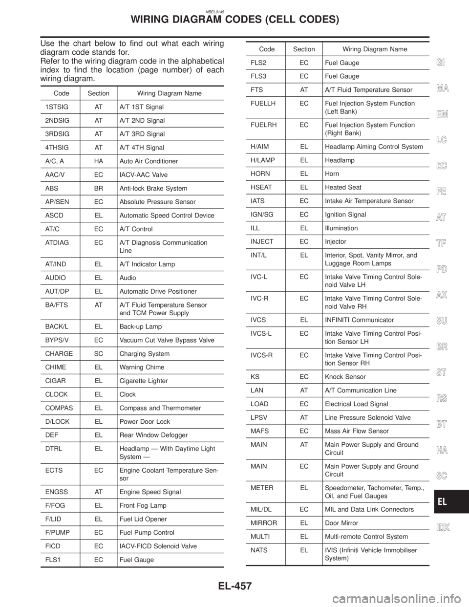
NBEL0145
Use the chart below to find out what each wiring
diagram code stands for.
Refer to the wiring diagram code in the alphabetical
index to find the location (page number) of each
wiring diagram.
Code Section Wiring Diagram Name
1STSIG AT A/T 1ST Signal
2NDSIG AT A/T 2ND Signal
3RDSIG AT A/T 3RD Signal
4THSIG AT A/T 4TH Signal
A/C, A HA Auto Air Conditioner
AAC/V EC IACV-AAC Valve
ABS BR Anti-lock Brake System
AP/SEN EC Absolute Pressure Sensor
ASCD EL Automatic Speed Control Device
AT/C EC A/T Control
ATDIAG EC A/T Diagnosis Communication
Line
AT/IND EL A/T Indicator Lamp
AUDIO EL Audio
AUT/DP EL Automatic Drive Positioner
BA/FTS AT A/T Fluid Temperature Sensor
and TCM Power Supply
BACK/L EL Back-up Lamp
BYPS/V EC Vacuum Cut Valve Bypass Valve
CHARGE SC Charging System
CHIME EL Warning Chime
CIGAR EL Cigarette Lighter
CLOCK EL Clock
COMPAS EL Compass and Thermometer
D/LOCK EL Power Door Lock
DEF EL Rear Window Defogger
DTRL EL Headlamp Ð With Daytime Light
System Ð
ECTS EC Engine Coolant Temperature Sen-
sor
ENGSS AT Engine Speed Signal
F/FOG EL Front Fog Lamp
F/LID EL Fuel Lid Opener
F/PUMP EC Fuel Pump Control
FICD EC IACV-FICD Solenoid Valve
FLS1 EC Fuel Gauge
Code Section Wiring Diagram Name
FLS2 EC Fuel Gauge
FLS3 EC Fuel Gauge
FTS AT A/T Fluid Temperature Sensor
FUELLH EC Fuel Injection System Function
(Left Bank)
FUELRH EC Fuel Injection System Function
(Right Bank)
H/AIM EL Headlamp Aiming Control System
H/LAMP EL Headlamp
HORN EL Horn
HSEAT EL Heated Seat
IATS EC Intake Air Temperature Sensor
IGN/SG EC Ignition Signal
ILL EL Illumination
INJECT EC Injector
INT/L EL Interior, Spot, Vanity Mirror, and
Luggage Room Lamps
IVC-L EC Intake Valve Timing Control Sole-
noid Valve LH
IVC-R EC Intake Valve Timing Control Sole-
noid Valve RH
IVCS EL INFINITI Communicator
IVCS-L EC Intake Valve Timing Control Posi-
tion Sensor LH
IVCS-R EC Intake Valve Timing Control Posi-
tion Sensor RH
KS EC Knock Sensor
LAN AT A/T Communication Line
LOAD EC Electrical Load Signal
LPSV AT Line Pressure Solenoid Valve
MAFS EC Mass Air Flow Sensor
MAIN AT Main Power Supply and Ground
Circuit
MAIN EC Main Power Supply and Ground
Circuit
METER EL Speedometer, Tachometer, Temp.,
Oil, and Fuel Gauges
MIL/DL EC MIL and Data Link Connectors
MIRROR EL Door Mirror
MULTI EL Multi-remote Control System
NATS EL IVIS (Infiniti Vehicle Immobiliser
System)
GI
MA
EM
LC
EC
FE
AT
TF
PD
AX
SU
BR
ST
RS
BT
HA
SC
IDX
WIRING DIAGRAM CODES (CELL CODES)
EL-457
Page 1654 of 2395

SEM484GA
1. Heated oxygen sensor 1 (front)
(bank 1)
2. Heated oxygen sensor 1 (front)
(bank 2)
3. TWC (manifold)4. Thermostat with water inlet
5. Exhaust manifold
6. Thermal transmitter
7. Engine coolant temperature8. Water control valve
9. Water outlet housing
10. Cylinder block water outlet
GI
MA
LC
EC
FE
AT
TF
PD
AX
SU
BR
ST
RS
BT
HA
SC
EL
IDX
OUTER COMPONENT PARTS
Removal and Installation (Cont'd)
EM-11
Page 1796 of 2395
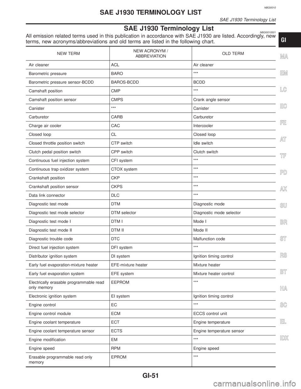
NBGI0010
SAE J1930 Terminology ListNBGI0010S01All emission related terms used in this publication in accordance with SAE J1930 are listed. Accordingly, new
terms, new acronyms/abbreviations and old terms are listed in the following chart.
NEW TERMNEW ACRONYM /
ABBREVIATIONOLD TERM
Air cleaner ACL Air cleaner
Barometric pressure BARO ***
Barometric pressure sensor-BCDD BAROS-BCDD BCDD
Camshaft position CMP ***
Camshaft position sensor CMPS Crank angle sensor
Canister *** Canister
Carburetor CARB Carburetor
Charge air cooler CAC Intercooler
Closed loop CL Closed loop
Closed throttle position switch CTP switch Idle switch
Clutch pedal position switch CPP switch Clutch switch
Continuous fuel injection system CFI system ***
Continuous trap oxidizer system CTOX system ***
Crankshaft position CKP ***
Crankshaft position sensor CKPS ***
Data link connector DLC ***
Diagnostic test mode DTM Diagnostic mode
Diagnostic test mode selector DTM selector Diagnostic mode selector
Diagnostic test mode I DTM I Mode I
Diagnostic test mode II DTM II Mode II
Diagnostic trouble code DTC Malfunction code
Direct fuel injection system DFI system ***
Distributor ignition system DI system Ignition timing control
Early fuel evaporation-mixture heater EFE-mixture heater Mixture heater
Early fuel evaporation system EFE system Mixture heater control
Electrically erasable programmable read
only memoryEEPROM ***
Electronic ignition system EI system Ignition timing control
Engine control EC ***
Engine control module ECM ECCS control unit
Engine coolant temperature ECT Engine temperature
Engine coolant temperature sensor ECTS Engine temperature sensor
Engine modification EM ***
Engine speed RPM Engine speed
Erasable programmable read only
memoryEPROM ***MA
EM
LC
EC
FE
AT
TF
PD
AX
SU
BR
ST
RS
BT
HA
SC
EL
IDX
SAE J1930 TERMINOLOGY LIST
SAE J1930 Terminology List
GI-51
Page 1821 of 2395
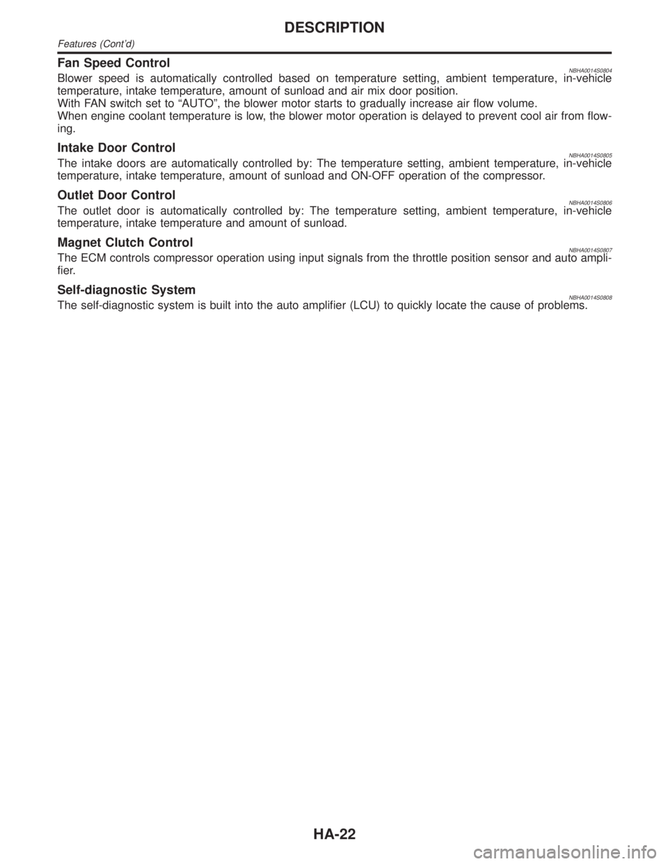
Fan Speed ControlNBHA0014S0804Blower speed is automatically controlled based on temperature setting, ambient temperature, in-vehicle
temperature, intake temperature, amount of sunload and air mix door position.
With FAN switch set to ªAUTOº, the blower motor starts to gradually increase air flow volume.
When engine coolant temperature is low, the blower motor operation is delayed to prevent cool air from flow-
ing.
Intake Door ControlNBHA0014S0805The intake doors are automatically controlled by: The temperature setting, ambient temperature, in-vehicle
temperature, intake temperature, amount of sunload and ON-OFF operation of the compressor.
Outlet Door ControlNBHA0014S0806The outlet door is automatically controlled by: The temperature setting, ambient temperature, in-vehicle
temperature, intake temperature and amount of sunload.
Magnet Clutch ControlNBHA0014S0807The ECM controls compressor operation using input signals from the throttle position sensor and auto ampli-
fier.
Self-diagnostic SystemNBHA0014S0808The self-diagnostic system is built into the auto amplifier (LCU) to quickly locate the cause of problems.
DESCRIPTION
Features (Cont'd)
HA-22
Page 1840 of 2395
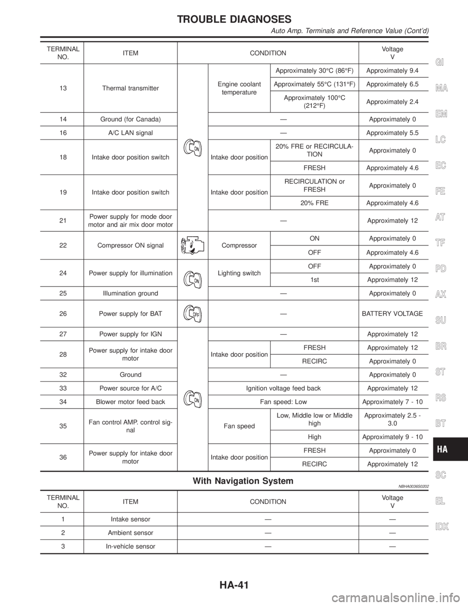
TERMINAL
NO.ITEM CONDITIONVoltage
V
13 Thermal transmitter
Engine coolant
temperatureApproximately 30ÉC (86ÉF) Approximately 9.4
Approximately 55ÉC (131ÉF) Approximately 6.5
Approximately 100ÉC
(212ÉF)Approximately 2.4
14 Ground (for Canada) Ð Approximately 0
16 A/C LAN signal Ð Approximately 5.5
18 Intake door position switch Intake door position20% FRE or RECIRCULA-
TIONApproximately 0
FRESH Approximately 4.6
19 Intake door position switch Intake door positionRECIRCULATION or
FRESHApproximately 0
20% FRE Approximately 4.6
21Power supply for mode door
motor and air mix door motorÐ Approximately 12
22 Compressor ON signal
CompressorON Approximately 0
OFF Approximately 4.6
24 Power supply for illumination
Lighting switchOFF Approximately 0
1st Approximately 12
25 Illumination ground Ð Approximately 0
26 Power supply for BAT
Ð BATTERY VOLTAGE
27 Power supply for IGN
Ð Approximately 12
28Power supply for intake door
motorIntake door positionFRESH Approximately 12
RECIRC Approximately 0
32 Ground Ð Approximately 0
33 Power source for A/C Ignition voltage feed back Approximately 12
34 Blower motor feed back Fan speed: Low Approximately7-10
35Fan control AMP. control sig-
nalFan speedLow, Middle low or Middle
highApproximately 2.5 -
3.0
High Approximately9-10
36Power supply for intake door
motorIntake door positionFRESH Approximately 0
RECIRC Approximately 12
With Navigation SystemNBHA0036S0202
TERMINAL
NO.ITEM CONDITIONVoltage
V
1 Intake sensor Ð Ð
2 Ambient sensor Ð Ð
3 In-vehicle sensor Ð Ð
GI
MA
EM
LC
EC
FE
AT
TF
PD
AX
SU
BR
ST
RS
BT
SC
EL
IDX
TROUBLE DIAGNOSES
Auto Amp. Terminals and Reference Value (Cont'd)
HA-41
Page 1841 of 2395
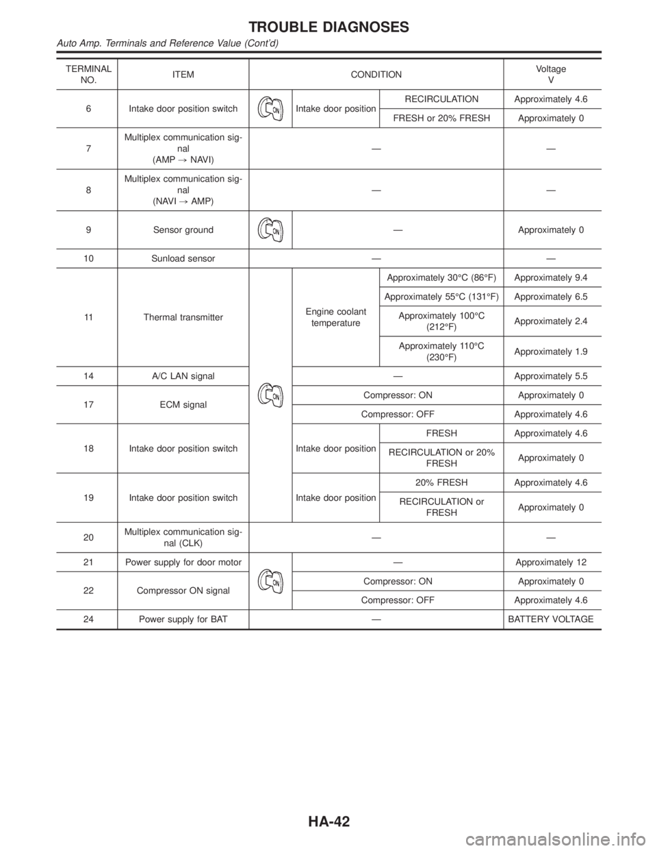
TERMINAL
NO.ITEM CONDITIONVoltage
V
6 Intake door position switch
Intake door positionRECIRCULATION Approximately 4.6
FRESH or 20% FRESH Approximately 0
7Multiplex communication sig-
nal
(AMP,NAVI)ÐÐ
8Multiplex communication sig-
nal
(NAVI,AMP)ÐÐ
9 Sensor ground
Ð Approximately 0
10 Sunload sensor Ð Ð
11 Thermal transmitter
Engine coolant
temperatureApproximately 30ÉC (86ÉF) Approximately 9.4
Approximately 55ÉC (131ÉF) Approximately 6.5
Approximately 100ÉC
(212ÉF)Approximately 2.4
Approximately 110ÉC
(230ÉF)Approximately 1.9
14 A/C LAN signal Ð Approximately 5.5
17 ECM signalCompressor: ON Approximately 0
Compressor: OFF Approximately 4.6
18 Intake door position switch Intake door positionFRESH Approximately 4.6
RECIRCULATION or 20%
FRESHApproximately 0
19 Intake door position switch Intake door position20% FRESH Approximately 4.6
RECIRCULATION or
FRESHApproximately 0
20Multiplex communication sig-
nal (CLK)ÐÐ
21 Power supply for door motor
Ð Approximately 12
22 Compressor ON signalCompressor: ON Approximately 0
Compressor: OFF Approximately 4.6
24 Power supply for BAT Ð BATTERY VOLTAGE
TROUBLE DIAGNOSES
Auto Amp. Terminals and Reference Value (Cont'd)
HA-42
Page 1896 of 2395
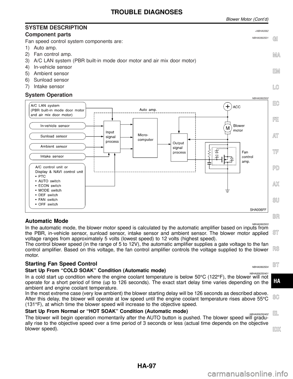
SYSTEM DESCRIPTION=NBHA0062Component partsNBHA0062S01Fan speed control system components are:
1) Auto amp.
2) Fan control amp.
3) A/C LAN system (PBR built-in mode door motor and air mix door motor)
4) In-vehicle sensor
5) Ambient sensor
6) Sunload sensor
7) Intake sensor
System OperationNBHA0062S02
SHA006FF
Automatic ModeNBHA0062S03In the automatic mode, the blower motor speed is calculated by the automatic amplifier based on inputs from
the PBR, in-vehicle sensor, sunload sensor, intake sensor and ambient sensor. The blower motor applied
voltage ranges from approximately 5 volts (lowest speed) to 12 volts (highest speed).
The control blower speed (in the range of 5 to 12V), the automatic amplifier supplies a gate voltage to the fan
control amplifier. Based on this voltage, the fan control amplifier controls the voltage supplied to the blower
motor.
Starting Fan Speed ControlNBHA0062S04Start Up From ªCOLD SOAKº Condition (Automatic mode)NBHA0062S0401In a cold start up condition where the engine coolant temperature is below 50ÉC (122ÉF), the blower will not
operate for a short period of time (up to 126 seconds). The exact start delay time varies depending on the
ambient and engine coolant temperature.
In the most extreme case (very low ambient) the blower starting delay will be 126 seconds as described above.
After this delay, the blower will operate at low speed until the engine coolant temperature rises above 55ÉC
(131ÉF), at which time the blower speed will increase to the objective speed.
Start Up From Normal or ªHOT SOAKº Condition (Automatic mode)
NBHA0062S0402The blower will begin operation momentarily after the AUTO button is pushed. The blower speed will gradu-
ally rise to the objective speed over a time period of 3 seconds or less (actual time depends on the objective
blower speed).
GI
MA
EM
LC
EC
FE
AT
TF
PD
AX
SU
BR
ST
RS
BT
SC
EL
IDX
TROUBLE DIAGNOSES
Blower Motor (Cont'd)
HA-97