2001 INFINITI QX4 coolant temperature
[x] Cancel search: coolant temperaturePage 981 of 2395
DescriptionNBEC0691SYSTEM DESCRIPTIONNBEC0691S01
Sensor Input signal to ECM function ECM Actuator
Crankshaft positon sensor (POS) Engine speed (POS)
Intake valve
timing con-
trolIntake valve timing control sole-
noid valve Crankshaft position sensor (REF) Engine speed (REF)
Camshaft position sensor Engine speed
Engine coolant temperature sensor Engine coolant temperature
Vehicle speed sensor Vehicle speed
JEF349Z
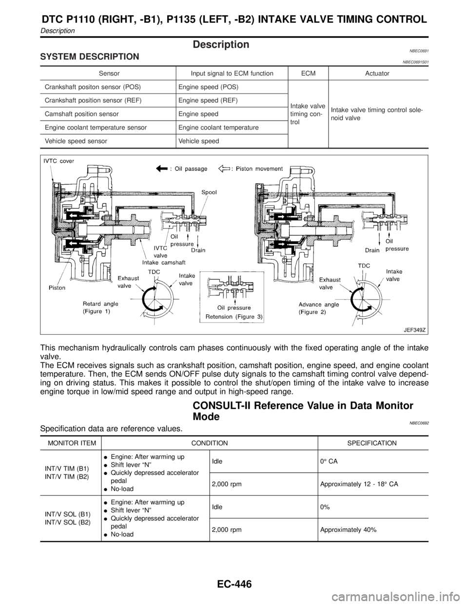
This mechanism hydraulically controls cam phases continuously with the fixed operating angle of the intake
valve.
The ECM receives signals such as crankshaft position, camshaft position, engine speed, and engine coolant
temperature. Then, the ECM sends ON/OFF pulse duty signals to the camshaft timing control valve depend-
ing on driving status. This makes it possible to control the shut/open timing of the intake valve to increase
engine torque in low/mid speed range and output in high-speed range.
CONSULT-II Reference Value in Data Monitor
Mode
NBEC0692Specification data are reference values.
MONITOR ITEM CONDITION SPECIFICATION
INT/V TIM (B1)
INT/V TIM (B2)IEngine: After warming up
IShift lever ªNº
IQuickly depressed accelerator
pedal
INo-loadIdle 0É CA
2,000 rpm Approximately 12 - 18É CA
INT/V SOL (B1)
INT/V SOL (B2)IEngine: After warming up
IShift lever ªNº
IQuickly depressed accelerator
pedal
INo-loadIdle 0%
2,000 rpm Approximately 40%
DTC P1110 (RIGHT, -B1), P1135 (LEFT, -B2) INTAKE VALVE TIMING CONTROL
Description
EC-446
Page 993 of 2395

DescriptionNBEC0523If DTC P1130 is displayed with P1165, first perform trouble diag-
nosis for DTC P1165, EC-493.
SYSTEM DESCRIPTIONNBEC0523S01
Sensor Input Signal to ECMECM func-
tionActuator
Throttle position sensor Throttle position
Swirl control
valve con-
trolSwirl control valve control sole-
noid valve
"Vacuum signal
Swirl control valve actuator
"
Swirl control valve Ignition switch Start signal
Crankshaft position sensor (POS) Engine speed (POS signal)
Crankshaft position sensor (REF) Engine speed (REF signal)
Mass air flow sensor Amount of intake air
Engine coolant temperature sensor Engine coolant temperature
This system has a swirl control valve in the intake passage of each
cylinder.
While idling and during low engine speed operation, the swirl con-
trol valve closes. Thus the velocity of the air in the intake passage
increases, promoting the vaporization of the fuel and producing a
swirl in the combustion chamber.
Because of this operation, this system tends to increase the burn-
ing speed of the gas mixture, improve fuel consumption, and
increase the stability in running conditions.
Also, except when idling and during low engine speed operation,
this system opens the swirl control valve. In this condition, this
system tends to increase power by improving intake efficiency via
reduction of intake flow resistance, intake flow.
The solenoid valve controls swirl control valve's shut/open condi-
tion. This solenoid valve is operated by the ECM.
Throttle position
sensor (Idle posi-
tion)Engine speedSwirl control valve
control solenoid
valveSwirl control valve
ON Below 3,200 rpm ON Closed
OFFLess than 3,200
rpmON Closed
More than 3,600
rpmOFF Open
When engine coolant temperature is below 10ÉC (50ÉF) and above 55ÉC (131ÉF),
swirl control valve is kept open regardless of above condition.
SEF446Z
DTC P1130 SWIRL CONTROL VALVE CONTROL SOLENOID VALVE
Description
EC-458
Page 994 of 2395

SEF002Z
COMPONENT DESCRIPTIONNBEC0523S02Swirl Control Valve Control Solenoid ValveNBEC0523S0201The swirl control valve control solenoid valve responds to signals
from the ECM. When the ECM sends an ON (ground) signal, the
solenoid valve is bypassed to apply intake manifold vacuum to the
swirl control valve actuator. This operation closes the swirl control
valve. When the ECM sends an OFF signal, the vacuum signal is
cut and the swirl control valve opens.
CONSULT-II Reference Value in Data Monitor
Mode
NBEC0524Specification data are reference values.
MONITOR ITEM CONDITION SPECIFICATION
SWRL CONT S/VIEngine speed: IdleEngine coolant temperature is
between 15ÉC (59ÉF) to 50ÉC
(122ÉF).ON
Engine coolant temperature is
above 55ÉC (131ÉF).OFF
ECM Terminals and Reference ValueNBEC0673Specification data are reference values and are measured between each terminal and ground.
CAUTION:
Do not use ECM ground terminals when measuring input/output voltage. Doing so may result in dam-
age to the ECM's transistor. Use a ground other than ECM terminals, such as the ground.
TERMI-
NAL
NO.WIRE
COLORITEM CONDITION DATA (DC Voltage)
29 GSwirl control valve con-
trol solenoid valve[Engine is running]
IIdle speed
IEngine coolant temperature is between 15 to
50ÉC (59 to 122ÉF).0 - 1.0V
[Engine is running]
IIdle speed
IEngine coolant temperature is above 55ÉC
(131ÉF).BATTERY VOLTAGE
(11 - 14V)
On Board Diagnosis LogicNBEC0526Malfunction is detected when
(Malfunction A)An improper voltage signal is sent to ECM through
swirl control valve control solenoid valve,
(Malfunction B)The vacuum signal is not sent to swirl control
valve under specified driving conditions, even though swirl control
valve control solenoid valve is ON,
(Malfunction C)The vacuum signal is sent to swirl control valve
even though swirl control valve control solenoid valve is OFF.
GI
MA
EM
LC
FE
AT
TF
PD
AX
SU
BR
ST
RS
BT
HA
SC
EL
IDX
DTC P1130 SWIRL CONTROL VALVE CONTROL SOLENOID VALVE
Description (Cont'd)
EC-459
Page 1028 of 2395
SEF999Y
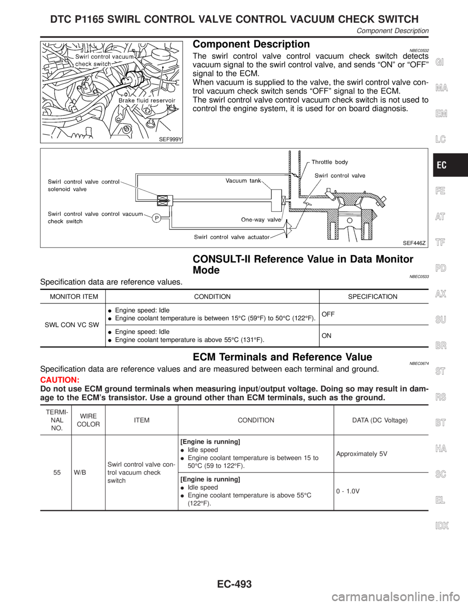
Component DescriptionNBEC0532The swirl control valve control vacuum check switch detects
vacuum signal to the swirl control valve, and sends ªONº or ªOFFº
signal to the ECM.
When vacuum is supplied to the valve, the swirl control valve con-
trol vacuum check switch sends ªOFFº signal to the ECM.
The swirl control valve control vacuum check switch is not used to
control the engine system, it is used for on board diagnosis.
SEF446Z
CONSULT-II Reference Value in Data Monitor
Mode
NBEC0533Specification data are reference values.
MONITOR ITEM CONDITION SPECIFICATION
SWL CON VC SWIEngine speed: Idle
IEngine coolant temperature is between 15ÉC (59ÉF) to 50ÉC (122ÉF).OFF
IEngine speed: Idle
IEngine coolant temperature is above 55ÉC (131ÉF).ON
ECM Terminals and Reference ValueNBEC0674Specification data are reference values and are measured between each terminal and ground.
CAUTION:
Do not use ECM ground terminals when measuring input/output voltage. Doing so may result in dam-
age to the ECM's transistor. Use a ground other than ECM terminals, such as the ground.
TERMI-
NAL
NO.WIRE
COLORITEM CONDITION DATA (DC Voltage)
55 W/BSwirl control valve con-
trol vacuum check
switch[Engine is running]
IIdle speed
IEngine coolant temperature is between 15 to
50ÉC (59 to 122ÉF).Approximately 5V
[Engine is running]
IIdle speed
IEngine coolant temperature is above 55ÉC
(122ÉF).0 - 1.0V
GI
MA
EM
LC
FE
AT
TF
PD
AX
SU
BR
ST
RS
BT
HA
SC
EL
IDX
DTC P1165 SWIRL CONTROL VALVE CONTROL VACUUM CHECK SWITCH
Component Description
EC-493
Page 1076 of 2395
DescriptionNBEC0319SYSTEM DESCRIPTIONNBEC0319S01
Sensor Input Signal to ECMECM
functionActuator
Crankshaft position sensor (POS) Engine speed (POS signal)
EVAP can-
ister purge
flow controlEVAP canister purge volume
control solenoid valve Crankshaft position sensor (REF) Engine speed (REF signal)
Mass air flow sensor Amount of intake air
Engine coolant temperature sensor Engine coolant temperature
Ignition switch Start signal
Throttle position sensor Throttle position
Throttle position switch Closed throttle position
Heated oxygen sensorsDensity of oxygen in exhaust gas
(Mixture ratio feedback signal)
Fuel tank temperature sensor Fuel temperature in fuel tank
Vehicle speed sensor Vehicle speed
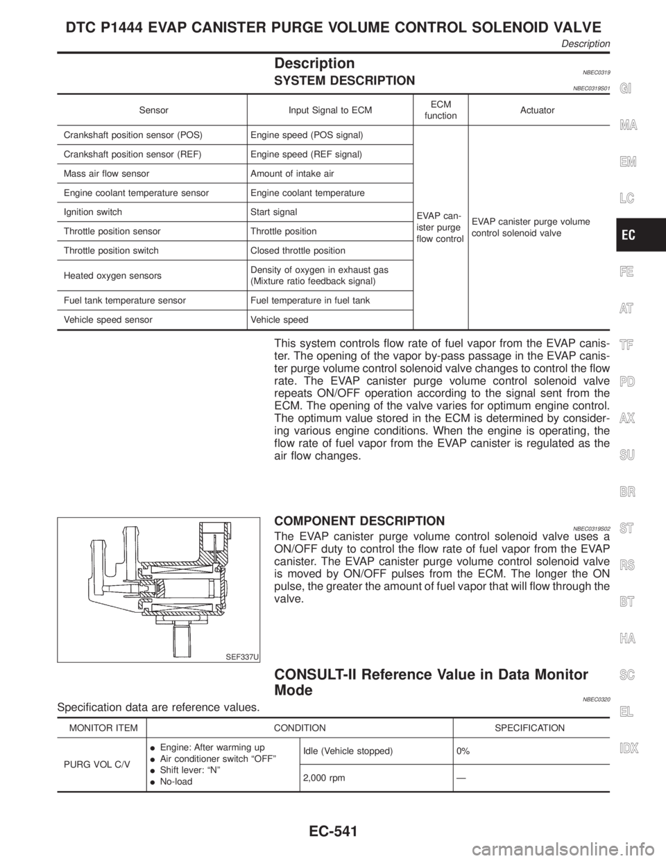
This system controls flow rate of fuel vapor from the EVAP canis-
ter. The opening of the vapor by-pass passage in the EVAP canis-
ter purge volume control solenoid valve changes to control the flow
rate. The EVAP canister purge volume control solenoid valve
repeats ON/OFF operation according to the signal sent from the
ECM. The opening of the valve varies for optimum engine control.
The optimum value stored in the ECM is determined by consider-
ing various engine conditions. When the engine is operating, the
flow rate of fuel vapor from the EVAP canister is regulated as the
air flow changes.
SEF337U
COMPONENT DESCRIPTIONNBEC0319S02The EVAP canister purge volume control solenoid valve uses a
ON/OFF duty to control the flow rate of fuel vapor from the EVAP
canister. The EVAP canister purge volume control solenoid valve
is moved by ON/OFF pulses from the ECM. The longer the ON
pulse, the greater the amount of fuel vapor that will flow through the
valve.
CONSULT-II Reference Value in Data Monitor
Mode
NBEC0320Specification data are reference values.
MONITOR ITEM CONDITION SPECIFICATION
PURG VOL C/VIEngine: After warming up
IAir conditioner switch ªOFFº
IShift lever: ªNº
INo-loadIdle (Vehicle stopped) 0%
2,000 rpm Ð
GI
MA
EM
LC
FE
AT
TF
PD
AX
SU
BR
ST
RS
BT
HA
SC
EL
IDX
DTC P1444 EVAP CANISTER PURGE VOLUME CONTROL SOLENOID VALVE
Description
EC-541
Page 1097 of 2395
IEVAP canister vent control valve
SEF207Y
SEF208Y
SEF238Y
DTC Confirmation ProcedureNBEC0335CAUTION:
Always drive vehicle at a safe speed.
NOTE:
If ªDTC Confirmation Procedureº has been previously conducted,
always turn ignition switch ªOFFº and wait at least 10 seconds
before conducting the next test.
TESTING CONDITION:
Always perform test at a temperature of 5ÉC (41ÉF) or more.
WITH CONSULT-IINBEC0335S011) Start engine and warm it up to normal operating temperature.
2) Turn ignition switch ªOFFº and wait at least 10 seconds.
3) Start engine and let it idle for at least 70 seconds.
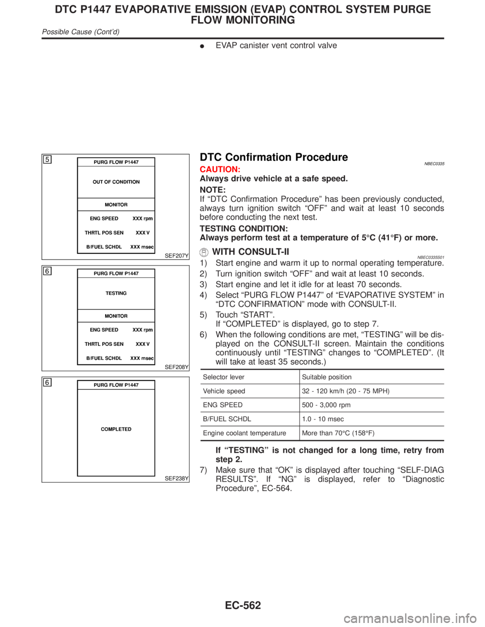
4) Select ªPURG FLOW P1447º of ªEVAPORATIVE SYSTEMº in
ªDTC CONFIRMATIONº mode with CONSULT-II.
5) Touch ªSTARTº.
If ªCOMPLETEDº is displayed, go to step 7.
6) When the following conditions are met, ªTESTINGº will be dis-
played on the CONSULT-II screen. Maintain the conditions
continuously until ªTESTINGº changes to ªCOMPLETEDº. (It
will take at least 35 seconds.)
Selector lever Suitable position
Vehicle speed 32 - 120 km/h (20 - 75 MPH)
ENG SPEED 500 - 3,000 rpm
B/FUEL SCHDL 1.0 - 10 msec
Engine coolant temperature More than 70ÉC (158ÉF)
If ªTESTINGº is not changed for a long time, retry from
step 2.
7) Make sure that ªOKº is displayed after touching ªSELF-DIAG
RESULTSº. If ªNGº is displayed, refer to ªDiagnostic
Procedureº, EC-564.
DTC P1447 EVAPORATIVE EMISSION (EVAP) CONTROL SYSTEM PURGE
FLOW MONITORING
Possible Cause (Cont'd)
EC-562
Page 1145 of 2395
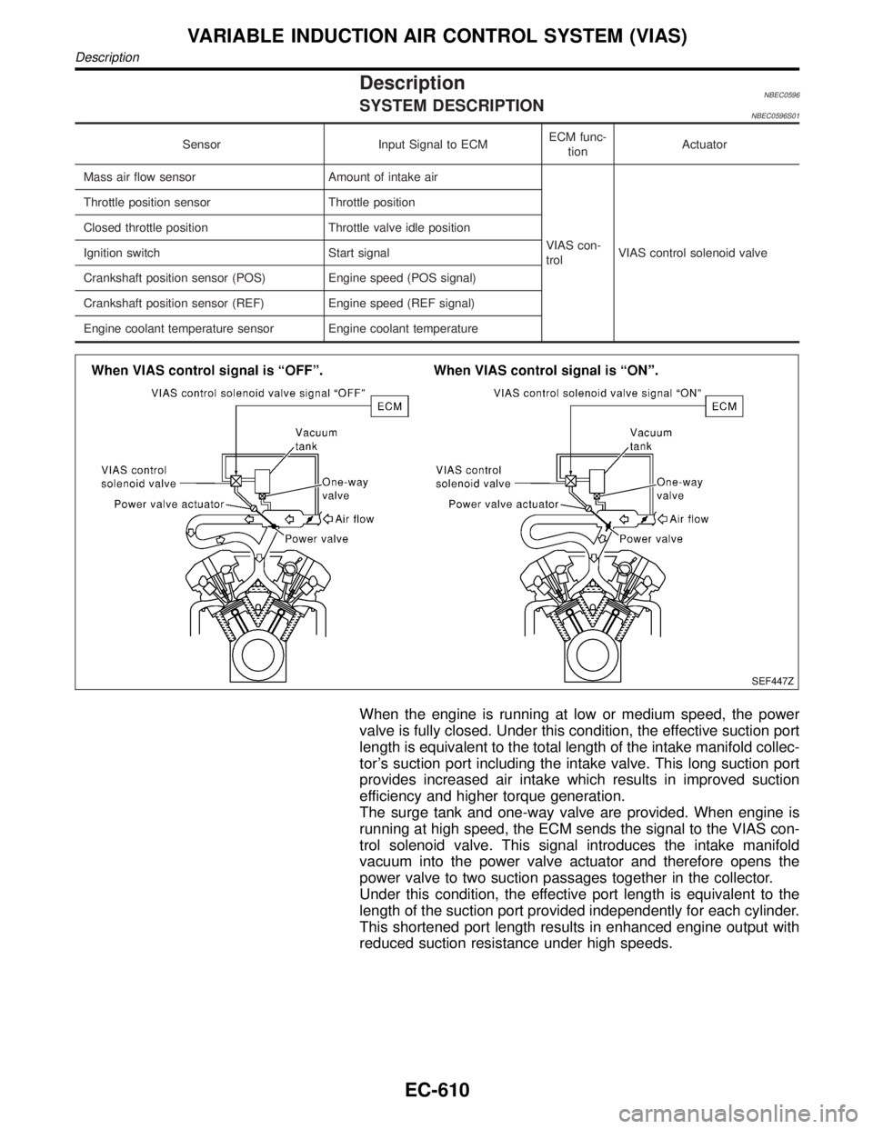
DescriptionNBEC0596SYSTEM DESCRIPTIONNBEC0596S01
Sensor Input Signal to ECMECM func-
tionActuator
Mass air flow sensor Amount of intake air
VIAS con-
trolVIAS control solenoid valve Throttle position sensor Throttle position
Closed throttle position Throttle valve idle position
Ignition switch Start signal
Crankshaft position sensor (POS) Engine speed (POS signal)
Crankshaft position sensor (REF) Engine speed (REF signal)
Engine coolant temperature sensor Engine coolant temperature
SEF447Z
When the engine is running at low or medium speed, the power
valve is fully closed. Under this condition, the effective suction port
length is equivalent to the total length of the intake manifold collec-
tor's suction port including the intake valve. This long suction port
provides increased air intake which results in improved suction
efficiency and higher torque generation.
The surge tank and one-way valve are provided. When engine is
running at high speed, the ECM sends the signal to the VIAS con-
trol solenoid valve. This signal introduces the intake manifold
vacuum into the power valve actuator and therefore opens the
power valve to two suction passages together in the collector.
Under this condition, the effective port length is equivalent to the
length of the suction port provided independently for each cylinder.
This shortened port length results in enhanced engine output with
reduced suction resistance under high speeds.
VARIABLE INDUCTION AIR CONTROL SYSTEM (VIAS)
Description
EC-610
Page 1184 of 2395
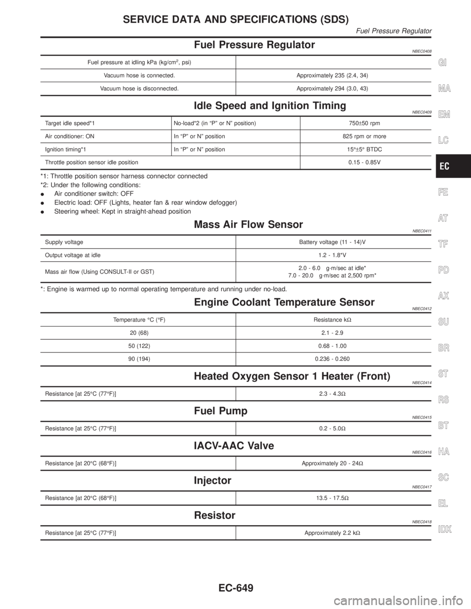
Fuel Pressure RegulatorNBEC0408
Fuel pressure at idling kPa (kg/cm2, psi)
Vacuum hose is connected. Approximately 235 (2.4, 34)
Vacuum hose is disconnected. Approximately 294 (3.0, 43)
Idle Speed and Ignition TimingNBEC0409
Target idle speed*1 No-load*2 (in ªPº or Nº position) 750±50 rpm
Air conditioner: ON In ªPº or Nº position 825 rpm or more
Ignition timing*1 In ªPº or Nº position 15ɱ5É BTDC
Throttle position sensor idle position0.15 - 0.85V
*1: Throttle position sensor harness connector connected
*2: Under the following conditions:
IAir conditioner switch: OFF
IElectric load: OFF (Lights, heater fan & rear window defogger)
ISteering wheel: Kept in straight-ahead position
Mass Air Flow SensorNBEC0411
Supply voltageBattery voltage (11 - 14)V
Output voltage at idle1.2 - 1.8*V
Mass air flow (Using CONSULT-II or GST)2.0 - 6.0 g´m/sec at idle*
7.0 - 20.0 g´m/sec at 2,500 rpm*
*: Engine is warmed up to normal operating temperature and running under no-load.
Engine Coolant Temperature SensorNBEC0412
Temperature ÉC (ÉF) Resistance kW
20 (68) 2.1 - 2.9
50 (122) 0.68 - 1.00
90 (194) 0.236 - 0.260
Heated Oxygen Sensor 1 Heater (Front)NBEC0414
Resistance [at 25ÉC (77ÉF)]2.3 - 4.3W
Fuel PumpNBEC0415
Resistance [at 25ÉC (77ÉF)]0.2 - 5.0W
IACV-AAC ValveNBEC0416
Resistance [at 20ÉC (68ÉF)]Approximately 20 - 24W
InjectorNBEC0417
Resistance [at 20ÉC (68ÉF)]13.5 - 17.5W
ResistorNBEC0418
Resistance [at 25ÉC (77ÉF)]Approximately 2.2 kW
GI
MA
EM
LC
FE
AT
TF
PD
AX
SU
BR
ST
RS
BT
HA
SC
EL
IDX
SERVICE DATA AND SPECIFICATIONS (SDS)
Fuel Pressure Regulator
EC-649