2001 INFINITI QX4 Oil sensor
[x] Cancel search: Oil sensorPage 1052 of 2395

SEF977Y
Component DescriptionNBEC0292The crankshaft position sensor (POS) is located on the oil pan
facing the gear teeth (cogs) of the signal plate (flywheel). It detects
the crankshaft position signal (1É signal).
The sensor consists of a permanent magnet, core and coil.
When engine is running, the gap between the sensor and the gear
teeth (cogs) will periodically change. Permeability near the sensor
also changes.
Due to the permeability change, the magnetic flux near the core is
changed. Therefore, the voltage signal generated in the coil is
changed.
The ECM receives the voltage signal and detects the crankshaft
position signal (1É signal).
CONSULT-II Reference Value in Data Monitor
Mode
NBEC0581Specification data are reference values.
MONITOR ITEM CONDITION SPECIFICATION
CKPS´RPM (POS)ITachometer: Connect
IRun engine and compare tachometer indication with the CONSULT-II
value.Almost the same speed as the
CONSULT-II value.
ENG SPEED
GI
MA
EM
LC
FE
AT
TF
PD
AX
SU
BR
ST
RS
BT
HA
SC
EL
IDX
DTC P1336 CRANKSHAFT POSITION SENSOR (CKPS) (POS) (COG)
Component Description
EC-517
Page 1307 of 2395

SEL062WA
Fuel Warning Lamp Sensor CheckNBEL01661. Turn ignition switch ªOFFº.
2. Disconnect fuel level sensor unit harness connector B12.
3. Connect a resistor (80W) between fuel tank gauge unit harness
connector terminals 2 and 3.
4. Turn ignition switch ªONº.
The fuel warning lamp should come on.
NOTE:
ECM might store the 1st trip DTC P0180 during this inspection.
If the DTC is stored in ECM memory, erase the DTC after recon-
necting fuel tank gauge unit harness connector.
Refer to EC-60, ªHOW TO ERASE EMISSION-RELATED DIAG-
NOSTIC INFORMATIONº.
MEL425F
Electrical Components InspectionNBEL0051OIL PRESSURE SWITCH CHECKNBEL0051S02
Oil pressure
kPa (kg/cm2, psi)Continuity
Engine startMore than 10 - 20
(0.1-0.2,1-3)NO
Engine stopLess than 10 - 20
(0.1-0.2,1-3)YES
Check the continuity between the terminals of oil pressure switch
and body ground.
SEL901F
DIODE CHECKNBEL0051S03ICheck continuity using an ohmmeter.
IDiode is functioning properly if test results are as shown in the
figure at left.
ICheck diodes at the combination meter harness connector
instead of checking them on the combination meter assembly.
Refer to EL-115, ªWARNING LAMPº wiring diagrams.
NOTE:
Specification may vary depending on the type of tester. Before
performing this inspection, be sure to refer to the instruction
manual for the tester to be used.
WARNING LAMPS
Fuel Warning Lamp Sensor Check
EL-122
Page 1642 of 2395
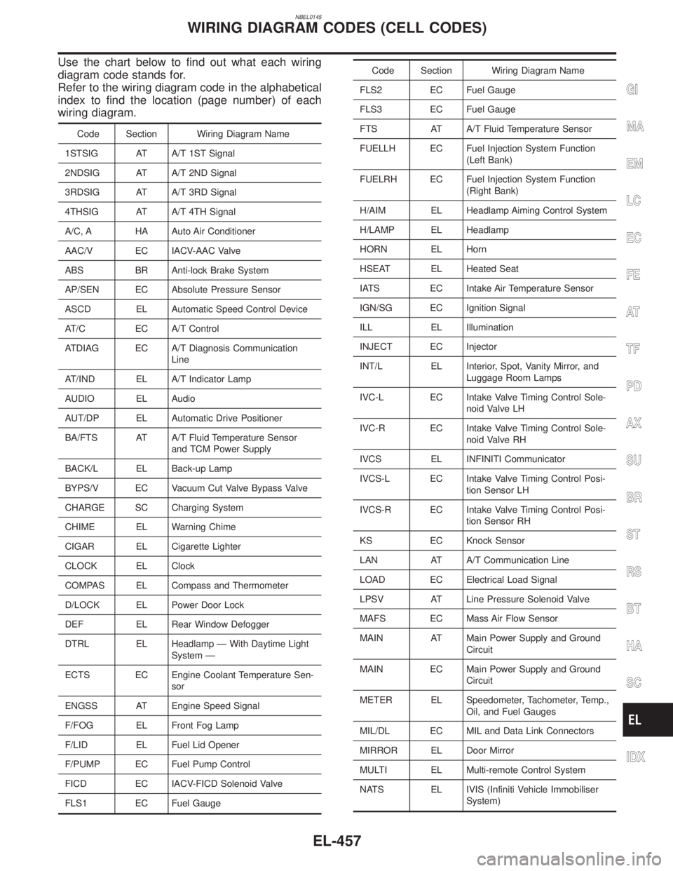
NBEL0145
Use the chart below to find out what each wiring
diagram code stands for.
Refer to the wiring diagram code in the alphabetical
index to find the location (page number) of each
wiring diagram.
Code Section Wiring Diagram Name
1STSIG AT A/T 1ST Signal
2NDSIG AT A/T 2ND Signal
3RDSIG AT A/T 3RD Signal
4THSIG AT A/T 4TH Signal
A/C, A HA Auto Air Conditioner
AAC/V EC IACV-AAC Valve
ABS BR Anti-lock Brake System
AP/SEN EC Absolute Pressure Sensor
ASCD EL Automatic Speed Control Device
AT/C EC A/T Control
ATDIAG EC A/T Diagnosis Communication
Line
AT/IND EL A/T Indicator Lamp
AUDIO EL Audio
AUT/DP EL Automatic Drive Positioner
BA/FTS AT A/T Fluid Temperature Sensor
and TCM Power Supply
BACK/L EL Back-up Lamp
BYPS/V EC Vacuum Cut Valve Bypass Valve
CHARGE SC Charging System
CHIME EL Warning Chime
CIGAR EL Cigarette Lighter
CLOCK EL Clock
COMPAS EL Compass and Thermometer
D/LOCK EL Power Door Lock
DEF EL Rear Window Defogger
DTRL EL Headlamp Ð With Daytime Light
System Ð
ECTS EC Engine Coolant Temperature Sen-
sor
ENGSS AT Engine Speed Signal
F/FOG EL Front Fog Lamp
F/LID EL Fuel Lid Opener
F/PUMP EC Fuel Pump Control
FICD EC IACV-FICD Solenoid Valve
FLS1 EC Fuel Gauge
Code Section Wiring Diagram Name
FLS2 EC Fuel Gauge
FLS3 EC Fuel Gauge
FTS AT A/T Fluid Temperature Sensor
FUELLH EC Fuel Injection System Function
(Left Bank)
FUELRH EC Fuel Injection System Function
(Right Bank)
H/AIM EL Headlamp Aiming Control System
H/LAMP EL Headlamp
HORN EL Horn
HSEAT EL Heated Seat
IATS EC Intake Air Temperature Sensor
IGN/SG EC Ignition Signal
ILL EL Illumination
INJECT EC Injector
INT/L EL Interior, Spot, Vanity Mirror, and
Luggage Room Lamps
IVC-L EC Intake Valve Timing Control Sole-
noid Valve LH
IVC-R EC Intake Valve Timing Control Sole-
noid Valve RH
IVCS EL INFINITI Communicator
IVCS-L EC Intake Valve Timing Control Posi-
tion Sensor LH
IVCS-R EC Intake Valve Timing Control Posi-
tion Sensor RH
KS EC Knock Sensor
LAN AT A/T Communication Line
LOAD EC Electrical Load Signal
LPSV AT Line Pressure Solenoid Valve
MAFS EC Mass Air Flow Sensor
MAIN AT Main Power Supply and Ground
Circuit
MAIN EC Main Power Supply and Ground
Circuit
METER EL Speedometer, Tachometer, Temp.,
Oil, and Fuel Gauges
MIL/DL EC MIL and Data Link Connectors
MIRROR EL Door Mirror
MULTI EL Multi-remote Control System
NATS EL IVIS (Infiniti Vehicle Immobiliser
System)
GI
MA
EM
LC
EC
FE
AT
TF
PD
AX
SU
BR
ST
RS
BT
HA
SC
IDX
WIRING DIAGRAM CODES (CELL CODES)
EL-457
Page 1643 of 2395
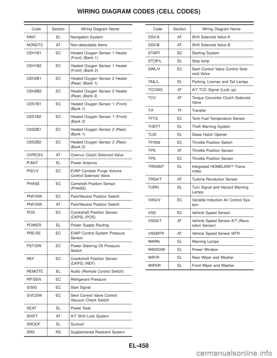
Code Section Wiring Diagram Name
NAVI EL Navigation System
NONDTC AT Non-detectable Items
O2H1B1 EC Heated Oxygen Sensor 1 Heater
(Front) (Bank 1)
O2H1B2 EC Heated Oxygen Sensor 1 Heater
(Front) (Bank 2)
O2H2B1 EC Heated Oxygen Sensor 2 Heater
(Rear) (Bank 1)
O2H2B2 EC Heated Oxygen Sensor 2 Heater
(Rear) (Bank 2)
O2S1B1 EC Heated Oxygen Sensor 1 (Front)
(Bank 1)
O2S1B2 EC Heated Oxygen Sensor 1 (Front)
(Bank 2)
O2S2B1 EC Heated Oxygen Sensor 2 (Rear)
(Bank 1)
O2S2B2 EC Heated Oxygen Sensor 2 (Rear)
(Bank 2)
OVRCSV AT Overrun Clutch Solenoid Valve
P/ANT EL Power Antenna
PGC/V EC EVAP Canister Purge Volume
Control Solenoid Valve
PHASE EC Camshaft Position Sensor
(PHASE)
PNP/SW EC Park/Neutral Position Switch
PNP/SW AT Park/Neutral Position Switch
POS EC Crankshaft Position Sensor
(CKPS) (POS)
POWER EL Power Supply Routing
PRE/SE EC EVAP Control System Pressure
Sensor
PST/SW EC Power Steering Oil Pressure
Switch
REF EC Crankshaft Position Sensor
(CKPS) (REF)
REMOTE EL Audio (Remote Control Switch)
RP/SEN EC Refrigerant Pressure
S/SIG EC Start Signal
S/VCSW EC Swirl Control Valve Control
Vacuum Check Switch
SEAT EL Power Seat
SHIFT AT A/T Shift Lock System
SROOF EL Sunroof
SRS RS Supplemental Restraint SystemCode Section Wiring Diagram Name
SSV/A AT Shift Solenoid Valve A
SSV/B AT Shift Solenoid Valve B
START SC Starting System
STOP/L EL Stop lamp
SWL/V EC Swirl Control Valve Control Sole-
noid Valve
TAIL/L EL Parking, License and Tail Lamps
TCCSIG AT A/T TCC Signal (Lock up)
TCV AT Torque Converter Clutch Solenoid
Valve
T/F TF Transfer
TFTS EC Tank Fuel Temperature Sensor
THEFT EL Theft Warning System
TLID EL Glass Hatch Opener
TP/SW EC Throttle Position Switch
TPS AT Throttle Position Sensor
TPS EC Throttle Position Sensor
TRNSMT EL Integrated HOMELINKYTrans-
mitter
TRSA/T AT Turbine Revolution Sensor
TURN EL Turn Signal and Hazard Warning
Lamps
VIAS/V EC Variable Induction Air Control Sys-
tem
VSS EC Vehicle Speed Sensor
VSSA/T AT Vehicle Speed Sensor A/T (Revo-
lution Sensor)
VSSMTR AT Vehicle Speed Sensor MTR
WARN EL Warning Lamps
WINDOW EL Power Window
WIP/R EL Rear Wiper and Washer
WIPER EL Front Wiper and Washer
WIRING DIAGRAM CODES (CELL CODES)
EL-458
Page 1658 of 2395
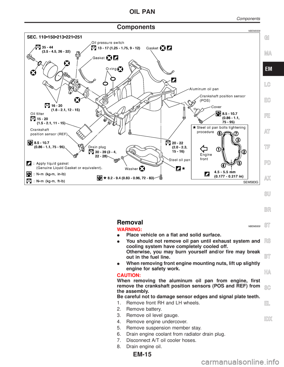
ComponentsNBEM0008
SEM583G
RemovalNBEM0009WARNING:
IPlace vehicle on a flat and solid surface.
IYou should not remove oil pan until exhaust system and
cooling system have completely cooled off.
Otherwise, you may burn yourself and/or fire may break
out in the fuel line.
IWhen removing front engine mounting nuts, lift up slightly
engine for safety work.
CAUTION:
When removing the aluminum oil pan from engine, first
remove the crankshaft position sensors (POS and REF) from
the assembly.
Be careful not to damage sensor edges and signal plate teeth.
1. Remove front RH and LH wheels.
2. Remove battery.
3. Remove oil level gauge.
4. Remove engine undercover.
5. Remove suspension member stay.
6. Drain engine coolant from radiator drain plug.
7. Disconnect A/T oil cooler hoses.
8. Drain engine oil.
GI
MA
LC
EC
FE
AT
TF
PD
AX
SU
BR
ST
RS
BT
HA
SC
EL
IDX
OIL PAN
Components
EM-15
Page 1659 of 2395
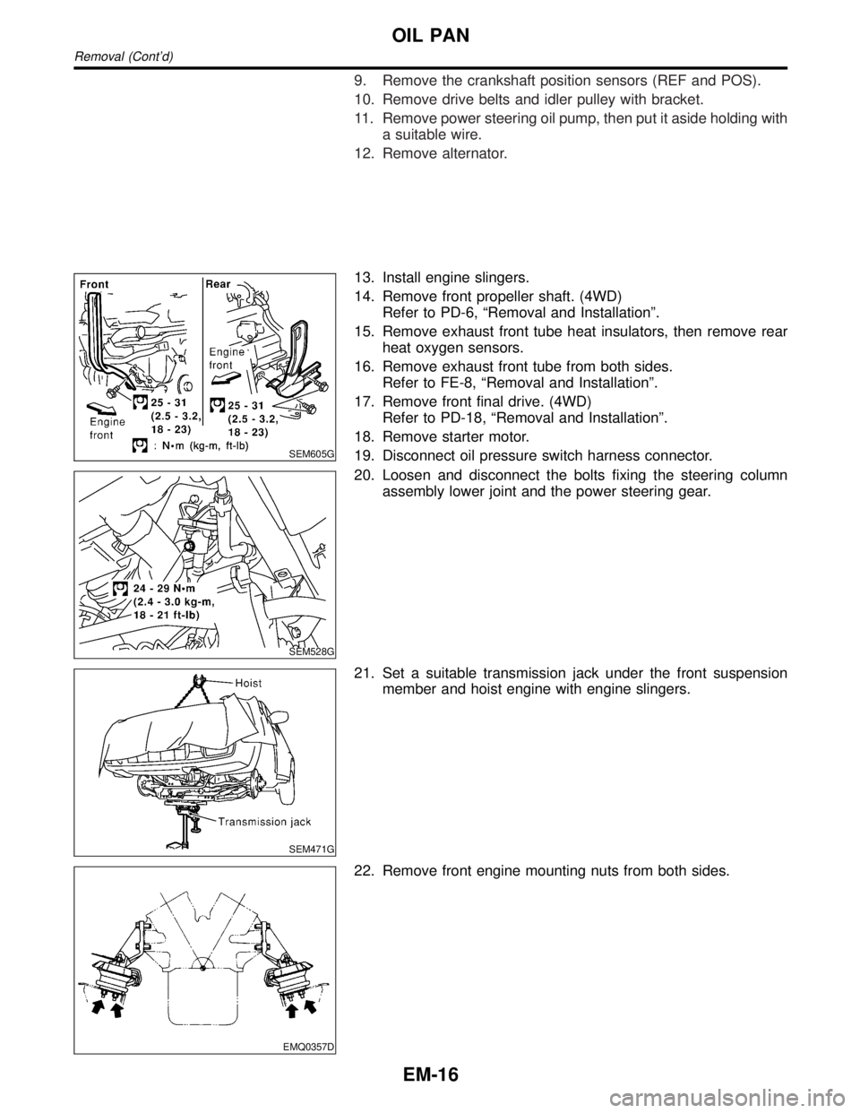
9. Remove the crankshaft position sensors (REF and POS).
10. Remove drive belts and idler pulley with bracket.
11. Remove power steering oil pump, then put it aside holding with
a suitable wire.
12. Remove alternator.
SEM605G
13. Install engine slingers.
14. Remove front propeller shaft. (4WD)
Refer to PD-6, ªRemoval and Installationº.
15. Remove exhaust front tube heat insulators, then remove rear
heat oxygen sensors.
16. Remove exhaust front tube from both sides.
Refer to FE-8, ªRemoval and Installationº.
17. Remove front final drive. (4WD)
Refer to PD-18, ªRemoval and Installationº.
18. Remove starter motor.
19. Disconnect oil pressure switch harness connector.
SEM528G
20. Loosen and disconnect the bolts fixing the steering column
assembly lower joint and the power steering gear.
SEM471G
21. Set a suitable transmission jack under the front suspension
member and hoist engine with engine slingers.
EMQ0357D
22. Remove front engine mounting nuts from both sides.
OIL PAN
Removal (Cont'd)
EM-16
Page 1666 of 2395
CAUTION:
IAfter removing timing chain, do not turn crankshaft and
camshaft separately, or valves will strike piston heads.
IWhen installing camshafts, chain tensioners, oil seals, or
other sliding parts, lubricate contacting surfaces with new
engine oil.
IApply new engine oil to bolt threads and seat surfaces
when installing camshaft sprockets and crankshaft pulley.
IBefore disconnecting fuel hose, release fuel pressure.
Refer to EC-39, ªFuel Pressure Releaseº.
IBe careful not to damage sensor edges.
IDo not spill engine coolant on drive belts.
RemovalNBEM00121. Release fuel pressure.
Refer to EC-39, ªFuel Pressure Releaseº.
2. Remove battery.
3. Remove radiator.
Refer to LC-19, ªREMOVAL AND INSTALLATIONº.
4. Drain engine oil.
5. Remove drive belts and idler pulley with brackets.
6. Remove cooling fan with bracket.
7. Remove engine cover.
8. Remove air duct with air cleaner case, collector, blow-by hose,
vacuum hoses, fuel hoses, water hoses, wires, harnesses,
connectors and so on.
9. Remove the air compressor, and tie it down using rope or the
like to keep it from interfering.
10. Remove the power steering oil pump and reservoir tank. Tie
them down using rope or the like to keep them from interfer-
ing.
11. Remove alternator.
12. Remove the following.
IVacuum gallery
IWater bypass pipe
IBrackets
GI
MA
LC
EC
FE
AT
TF
PD
AX
SU
BR
ST
RS
BT
HA
SC
EL
IDX
TIMING CHAIN
Components (Cont'd)
EM-23
Page 1676 of 2395

SEM439G
SEM440G
17. Install RH and LH rocker covers.
Rocker cover tightening procedure:
ITighten in numerical order as shown in the figure.
a. Tighten bolts 1 to 10 in that order to 6.9 to 8.8 N´m (0.7 to 0.9
kg-m, 61 to 78 in-lb).
b. Then tighten bolts 1 to 10 as indicated in figure to 6.9 to 8.8
N´m (0.7 to 0.9 kg-m, 61 to 78 in-lb).
18. Hang engine using the right and left side engine slingers with
a suitable hoist.
19. Set a suitable transmission jack under the suspension mem-
ber.
20. Remove right and left side engine mounting nuts.
21. Remove right and left side suspension member bolts.
22. Install aluminum oil pan. Refer to EM-18, ªInstallationº.
23. Set ring gear stopper using the mounting bolt hole.
IBe careful not to damage the signal plate teeth.
SEM417G
24. Install crankshaft pulley to crankshaft.
IAlign pointer with TDC mark on crankshaft pulley.
SEM531G
25. Install crankshaft pulley bolt.
ILubricate thread and seat surface of the bolt with new
engine oil.
a. Tighten to 39 to 49 N´m (4.0 to 5.0 kg-m, 29 to 36 ft-lb).
b. Put a paint mark on the crankshaft pulley.
SEM963E
c. Again tighten by turning 60É to 66É, about the angle from one
hexagon bolt head corner to another.
26. Install camshaft position sensor (PHASE), crankshaft position
sensors (REF)/(POS) and CVTC sensors.
27. Reinstall removed parts in the reverse order of removal.
IWhen installing fuel tube and intake manifold collectors, refer
to EM-12, ªTIGHTENING PROCEDURESº.
IAfter starting engine, keep idling for three minutes. Then
rev engine up to 3,000 rpm under no load to purge air from
the high-pressure chamber of the chain tensioners. The
engine may produce a rattling noise. This indicates that
GI
MA
LC
EC
FE
AT
TF
PD
AX
SU
BR
ST
RS
BT
HA
SC
EL
IDX
TIMING CHAIN
Installation (Cont'd)
EM-33