2001 INFINITI QX4 Oil sensor
[x] Cancel search: Oil sensorPage 1678 of 2395
SEM948E
ReplacementNBEM0015CAUTION:
When removing the oil pans, oil pump assembly and timing
chain from engine, first remove the camshaft position sensor
(PHASE), CVTC sensor and the crankshaft position sensors
(REF)/(POS) from the assembly.
Be careful not to damage sensor edges.
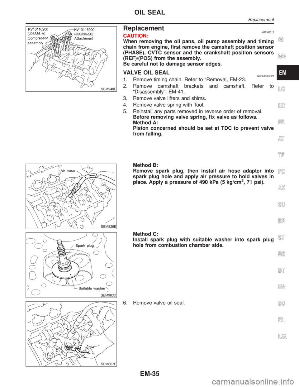
VALVE OIL SEALNBEM0015S011. Remove timing chain. Refer to ªRemoval, EM-23.
2. Remove camshaft brackets and camshaft. Refer to
ªDisassemblyº, EM-41.
3. Remove valve lifters and shims.
4. Remove valve spring with Tool.
5. Reinstall any parts removed in reverse order of removal.
Before removing valve spring, fix valve as follows.
Method A:
Piston concerned should be set at TDC to prevent valve
from falling.
SEM826E
Method B:
Remove spark plug, then install air hose adapter into
spark plug hole and apply air pressure to hold valves in
place. Apply a pressure of 490 kPa (5 kg/cm
2, 71 psi).
SEM983D
Method C:
Install spark plug with suitable washer into spark plug
hole from combustion chamber side.
SEM827E
6. Remove valve oil seal.
GI
MA
LC
EC
FE
AT
TF
PD
AX
SU
BR
ST
RS
BT
HA
SC
EL
IDX
OIL SEAL
Replacement
EM-35
Page 1679 of 2395
SEM828E
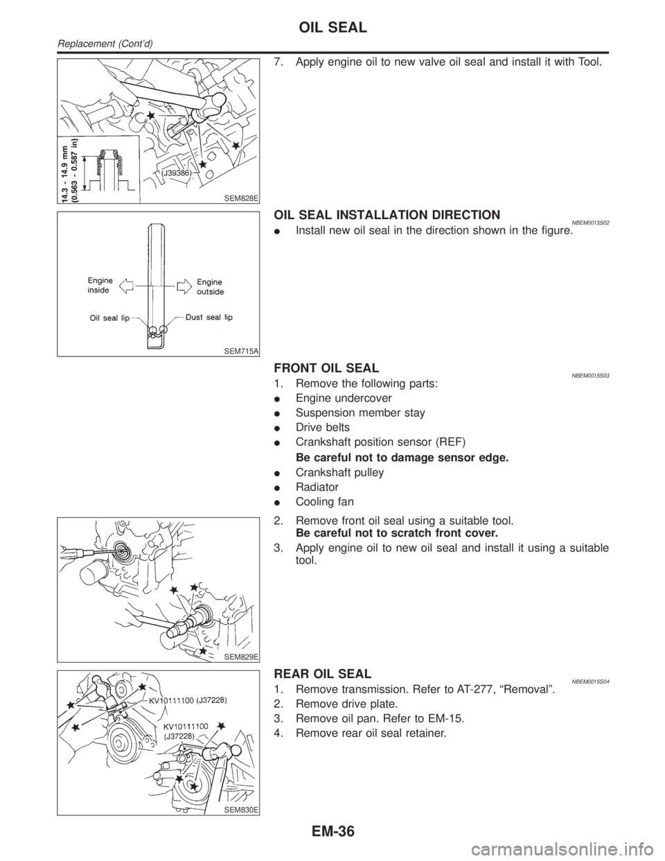
7. Apply engine oil to new valve oil seal and install it with Tool.
SEM715A
OIL SEAL INSTALLATION DIRECTIONNBEM0015S02IInstall new oil seal in the direction shown in the figure.
FRONT OIL SEALNBEM0015S031. Remove the following parts:
IEngine undercover
ISuspension member stay
IDrive belts
ICrankshaft position sensor (REF)
Be careful not to damage sensor edge.
ICrankshaft pulley
IRadiator
ICooling fan
SEM829E
2. Remove front oil seal using a suitable tool.
Be careful not to scratch front cover.
3. Apply engine oil to new oil seal and install it using a suitable
tool.
SEM830E
REAR OIL SEALNBEM0015S041. Remove transmission. Refer to AT-277, ªRemovalº.
2. Remove drive plate.
3. Remove oil pan. Refer to EM-15.
4. Remove rear oil seal retainer.
OIL SEAL
Replacement (Cont'd)
EM-36
Page 1702 of 2395

Rear Engine MountingNBEM0042S0102
SEM459G
SEM605G
SEM461G
SEM324F
1. Release fuel pressure.
Refer to EC-39, ªFuel pressure releaseº.
2. Remove engine hood and front RH and LH wheels.
3. Remove engine undercover and suspension member stay.
4. Drain coolant from radiator.
5. Remove the following parts.
IRadiator shroud
IRadiator
ICooling fan
IDrive belts
IBattery
IEngine cover
IThrottle wires
6. Air duct with air cleaner case.
7. Disconnect vacuum hoses, fuel hoses, heater hoses, EVAP
canister hoses, harnesses, connectors and so on.
8. Remove air conditioner compressor from bracket, then put it
aside holding with a suitable wire.
9. Remove power steering oil pump and reservoir tank with
bracket, then put it aside holding with a suitable wire.
10. Remove alternator.
11. Remove exhaust front tube heat insulators, then remove rear
heated oxygen sensors.
12. Remove exhaust front and rear tubes.
Refer to FE-8, ªRemoval and Installationº.
13. Remove transmission with transfer.
Refer to AT-277, ªRemovalº.
14. Remove TWC (manifold) heat insulators, then remove TWC
(manifold).
15. Install engine slingers.
16. Hoist engine with engine slingers and remove front engine
mounting nuts.
GI
MA
LC
EC
FE
AT
TF
PD
AX
SU
BR
ST
RS
BT
HA
SC
EL
IDX
ENGINE ASSEMBLY
Removal and Installation (Cont'd)
EM-59
Page 1704 of 2395

ComponentsNBEM0024
SEM584G
1. Rear oil seal retainer
2. Cylinder block
3. Knock sensor
4. Upper main bearing
5. Lower main bearing
6. Oil jet
7. Water drain plug (RH side)
8. Water drain plug (Water pump
side)9. Main bearing cap
10. Main bearing beam
11. Crankshaft
12. Pilot converter
13. Drive plate with signal plate
14. Drive plate reinforce plate
15. Oil ring
16. Piston pin17. Connecting rod bearing
18. Connecting rod
19. Piston
20. Top ring
21. 2nd ring
22. Baffle plate
23. Water drain plug (LH side)
GI
MA
LC
EC
FE
AT
TF
PD
AX
SU
BR
ST
RS
BT
HA
SC
EL
IDX
CYLINDER BLOCK
Components
EM-61
Page 1751 of 2395
IClean all disassembled parts in the designated liquid or solvent
prior to inspection or assembly.
IReplace oil seals, gaskets, packings, O-rings, locking washers,
cotter pins, self-locking nuts, etc. with new ones.
IReplace inner and outer races of tapered roller bearings and
needle bearings as a set.
IArrange the disassembled parts in accordance with their
assembled locations and sequence.
IDo not touch the terminals of electrical components which use
microcomputers (such as ECMs).
Static electricity may damage internal electronic components.
IAfter disconnecting vacuum or air hoses, attach a tag to indi-
cate the proper connection.
IUse only the fluids and lubricants specified in this manual.
IUse approved bonding agent, sealants or their equivalents
when required.
IUse tools and recommended special tools where specified for
safe and efficient service repairs.
IWhen repairing the fuel, oil, water, vacuum or exhaust
systems, check all affected lines for leaks.
IDispose of drained oil or the solvent used for cleaning parts in
an appropriate manner.
WARNING:
To prevent ECM from storing the diagnostic trouble codes, do
not carelessly disconnect the harness connectors which are
related to the engine control system and TCM (Transmission
Control Module) system. The connectors should be discon-
nected only when working according to the WORK FLOW of
TROUBLE DIAGNOSES in EC and AT sections.
SGI787
PRECAUTIONS FOR MULTIPORT FUEL INJECTION
SYSTEM OR ENGINE CONTROL SYSTEM
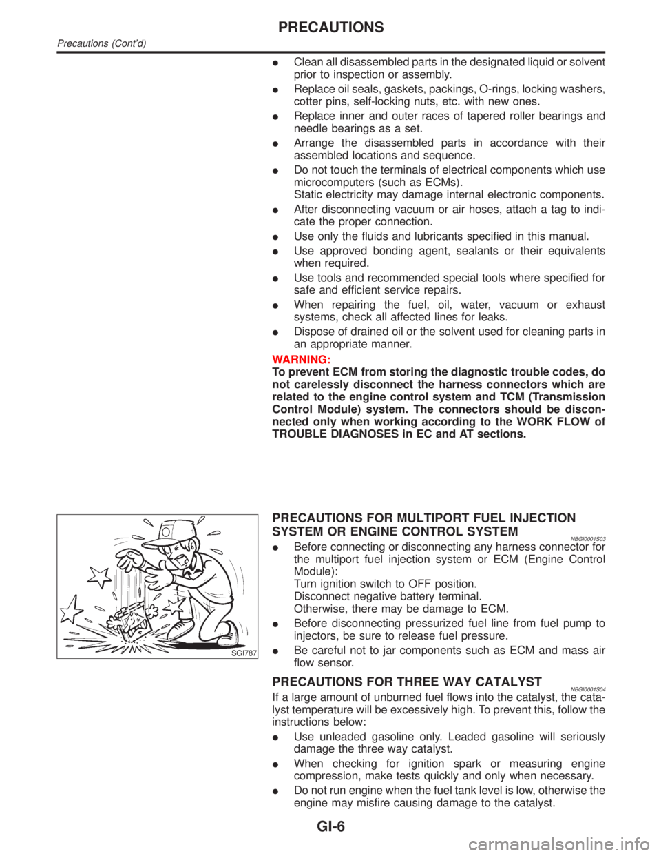
NBGI0001S03IBefore connecting or disconnecting any harness connector for
the multiport fuel injection system or ECM (Engine Control
Module):
Turn ignition switch to OFF position.
Disconnect negative battery terminal.
Otherwise, there may be damage to ECM.
IBefore disconnecting pressurized fuel line from fuel pump to
injectors, be sure to release fuel pressure.
IBe careful not to jar components such as ECM and mass air
flow sensor.
PRECAUTIONS FOR THREE WAY CATALYSTNBGI0001S04If a large amount of unburned fuel flows into the catalyst, the cata-
lyst temperature will be excessively high. To prevent this, follow the
instructions below:
IUse unleaded gasoline only. Leaded gasoline will seriously
damage the three way catalyst.
IWhen checking for ignition spark or measuring engine
compression, make tests quickly and only when necessary.
IDo not run engine when the fuel tank level is low, otherwise the
engine may misfire causing damage to the catalyst.
PRECAUTIONS
Precautions (Cont'd)
GI-6
Page 1801 of 2395
Supplemental Restraint System (SRS) ªAIR
BAGº and ªSEAT BELT PRE-TENSIONERº
NBHA0001The Supplemental Restraint System such as ªAIR BAGº and ªSEAT BELT PRE-TENSIONERº used along with
a seat belt, helps to reduce the risk or severity of injury to the driver and front passenger for certain types of
collision. The SRS system composition which is available to INFINITI QX4 is as follows:
IFor a frontal collision
The Supplemental Restraint System consists of driver air bag module (located in the center of the steer-
ing wheel), front passenger air bag module (located on the instrument panel on passenger side), seat belt
pre-tensioners, a diagnosis sensor unit, warning lamp, wiring harness and spiral cable.
IFor a side collision
The Supplemental Restraint System consists of front side air bag module (located in the outer side of front
seat), satellite sensor, diagnosis sensor unit (one of components of air bags for a frontal collision), wiring
harness, warning lamp (one of components of air bags for a frontal collision).
Information necessary to service the system safely is included in theRS sectionof this Service Manual.
WARNING:
ITo avoid rendering the SRS inoperative, which could increase the risk of personal injury or death
in the event of a collision which would result in air bag inflation, all maintenance must be performed
by an authorized INFINITI dealer.
IImproper maintenance, including incorrect removal and installation of the SRS, can lead to per-
sonal injury caused by unintentional activation of the system. For removal of Spiral Cable and Air
Bag Module, see the RS section.
IDo not use electrical test equipment on any circuit related to the SRS unless instructed to in this
Service Manual. Spiral cable and wiring harnesses covered with yellow insulation tape either just
before the harness connectors or for the complete harness are related to the SRS.
Precautions for Working with HFC-134a
(R-134a)
NBHA0002WARNING:
ICFC-12 (R-12) refrigerant and HFC-134a (R-134a) refrigerant are not compatible. If the refrigerants
are mixed and compressor failure is likely to occur, refer to ªCONTAMINATED REFRIGERANTº
below. To determine the purity of HFC-134a (R-134a) in the vehicle and recovery tank, use Refrig-
erant Recovery/Recycling Recharging equipment (ACR4) (J-39500-INF) and Refrigerant Identifier.
IUse only specified lubricant for the HFC-134a (R-134a) A/C system and HFC-134a (R-134a) compo-
nents. If lubricant other than that specified is used, compressor failure is likely to occur.
IThe specified HFC-134a (R-134a) lubricant rapidly absorbs moisture from the atmosphere. The fol-
lowing handling precautions must be observed:
a) When removing refrigerant components from a vehicle, immediately cap (seal) the component to
minimize the entry of moisture from the atmosphere.
b) When installing refrigerant components to a vehicle, do not remove the caps (unseal) until just
before connecting the components. Connect all refrigerant loop components as quickly as pos-
sible to minimize the entry of moisture into system.
c) Only use the specified lubricant from a sealed container. Immediately reseal containers of lubri-
cant. Without proper sealing, lubricant will become moisture saturated and should not be used.
d) Avoid breathing A/C refrigerant and lubricant vapor or mist. Exposure may irritate eyes, nose and
throat. Remove R-134a from the A/C system, using certified service equipment meeting require-
ments of SAE J2210 (R-134a recycling equipment), or J2209 (R-134a recovery equipment). If acci-
dental system discharge occurs, ventilate work area before resuming service. Additional health and
safety information may be obtained from refrigerant and lubricant manufacturers.
e) Do not allow lubricant (Nissan A/C System Oil Type S) to come in contact with styrofoam parts.
Damage may result.
CONTAMINATED REFRIGERANTNBHA0002S01If a refrigerant other than pure R-134a is identified in a vehicle, your options are:
IExplain to the customer that environmental regulations prohibit the release of contaminated refrigerant into
the atmosphere.
IExplain that recovery of the contaminated refrigerant could damage your service equipment and refriger-
ant supply.
PRECAUTIONS
Supplemental Restraint System (SRS) ªAIR BAGº and ªSEAT BELT PRE-TENSIONERº
HA-2
Page 1813 of 2395
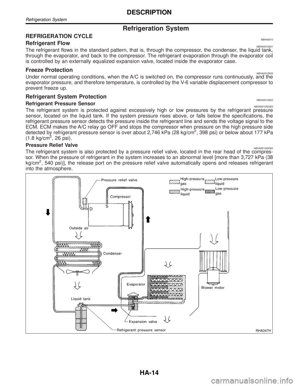
Refrigeration System
REFRIGERATION CYCLENBHA0010Refrigerant FlowNBHA0010S01The refrigerant flows in the standard pattern, that is, through the compressor, the condenser, the liquid tank,
through the evaporator, and back to the compressor. The refrigerant evaporation through the evaporator coil
is controlled by an externally equalized expansion valve, located inside the evaporator case.
Freeze ProtectionNBHA0010S02Under normal operating conditions, when the A/C is switched on, the compressor runs continuously, and the
evaporator pressure, and therefore temperature, is controlled by the V-6 variable displacement compressor to
prevent freeze up.
Refrigerant System ProtectionNBHA0010S03Refrigerant Pressure SensorNBHA0010S0303The refrigerant system is protected against excessively high or low pressures by the refrigerant pressure
sensor, located on the liquid tank. If the system pressure rises above, or falls below the specifications, the
refrigerant pressure sensor detects the pressure inside the refrigerant line and sends the voltage signal to the
ECM. ECM makes the A/C relay go OFF and stops the compressor when pressure on the high pressure side
detected by refrigerant pressure sensor is over about 2,746 kPa (28 kg/cm
2, 398 psi) or below about 177 kPa
(1.8 kg/cm2, 26 psi).
Pressure Relief Valve
NBHA0010S0302The refrigerant system is also protected by a pressure relief valve, located in the rear head of the compres-
sor. When the pressure of refrigerant in the system increases to an abnormal level [more than 3,727 kPa (38
kg/cm
2, 540 psi)], the release port on the pressure relief valve automatically opens and releases refrigerant
into the atmosphere.
RHA347H
DESCRIPTION
Refrigeration System
HA-14
Page 1905 of 2395

RHA094GB
SYSTEM DESCRIPTION=NBHA0066Auto amplifier controls compressor operation by ambient tempera-
ture and signal from ECM.
Low Temperature Protection ControlNBHA0066S01Auto amplifier will turn the compressor ªONº or ªOFFº as deter-
mined by a signal detected by ambient sensor.
When ambient temperatures are greater than ±2ÉC (28ÉF), the
compressor turns ªONº. The compressor turns ªOFFº when ambi-
ent temperatures are less than þ5ÉC (23ÉF).
RHA877H
DIAGNOSTIC PROCEDURENBHA0067SYMPTOM: Magnet clutch does not engage when AUTO
switch is ON.
1 CHECK POWER SUPPLY FOR COMPRESSOR
Disconnect compressor harness connector. Do approx. 12 volts exist between compressor harness terminal No. 1 and
body ground?
RHA096G
YesorNo
Ye s©Check magnet clutch coil.
1. If NG, replace magnet clutch. Refer to HA-150.
2. Go to self-diagnosis step-by-step procedure (HA-45) and perform self-diagnosis STEP
4.
Confirm that magnet clutch operation is normal.
No©Disconnect A/C relay. And GO TO 2.
TROUBLE DIAGNOSES
Magnet Clutch (Cont'd)
HA-106