2001 INFINITI QX4 ignition
[x] Cancel search: ignitionPage 1613 of 2395
Possible cause:
Ð: Vehicle running ---: IndicationDrive condition Service procedure
Loca-
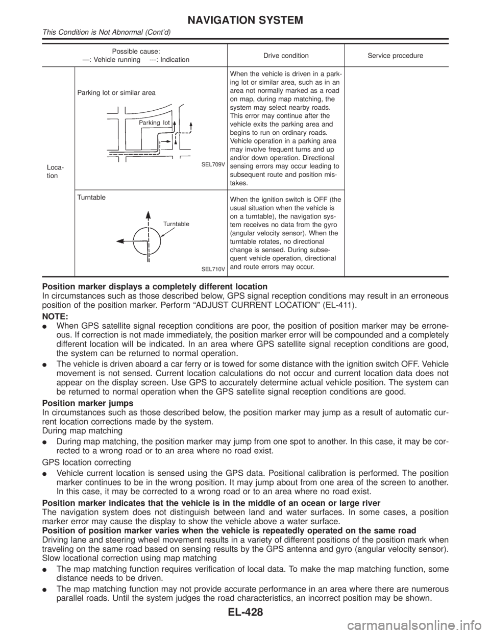
tionParking lot or similar area
SEL709V
When the vehicle is driven in a park-
ing lot or similar area, such as in an
area not normally marked as a road
on map, during map matching, the
system may select nearby roads.
This error may continue after the
vehicle exits the parking area and
begins to run on ordinary roads.
Vehicle operation in a parking area
may involve frequent turns and up
and/or down operation. Directional
sensing errors may occur leading to
subsequent route and position mis-
takes.
Turntable
SEL710V
When the ignition switch is OFF (the
usual situation when the vehicle is
on a turntable), the navigation sys-
tem receives no data from the gyro
(angular velocity sensor). When the
turntable rotates, no directional
change is sensed. During subse-
quent vehicle operation, directional
and route errors may occur.
Position marker displays a completely different location
In circumstances such as those described below, GPS signal reception conditions may result in an erroneous
position of the position marker. Perform ªADJUST CURRENT LOCATIONº (EL-411).
NOTE:
IWhen GPS satellite signal reception conditions are poor, the position of position marker may be errone-
ous. If correction is not made immediately, the position marker error will be compounded and a completely
different location will be indicated. In an area where GPS satellite signal reception conditions are good,
the system can be returned to normal operation.
IThe vehicle is driven aboard a car ferry or is towed for some distance with the ignition switch OFF. Vehicle
movement is not sensed. Current location calculations do not occur and current location data does not
appear on the display screen. Use GPS to accurately determine actual vehicle position. The system can
be returned to normal operation when the GPS satellite signal reception conditions are good.
Position marker jumps
In circumstances such as those described below, the position marker may jump as a result of automatic cur-
rent location corrections made by the system.
During map matching
IDuring map matching, the position marker may jump from one spot to another. In this case, it may be cor-
rected to a wrong road or to an area where no road exist.
GPS location correcting
IVehicle current location is sensed using the GPS data. Positional calibration is performed. The position
marker continues to be in the wrong position. It may jump about from one area of the screen to another.
In this case, it may be corrected to a wrong road or to an area where no road exist.
Position marker indicates that the vehicle is in the middle of an ocean or large river
The navigation system does not distinguish between land and water surfaces. In some cases, a position
marker error may cause the display to show the vehicle above a water surface.
Position of position marker varies when the vehicle is repeatedly operated on the same road
Driving lane and steering wheel movement results in a variety of different positions of the position mark when
traveling on the same road based on sensing results by the GPS antenna and gyro (angular velocity sensor).
Slow locational correction using map matching
IThe map matching function requires verification of local data. To make the map matching function, some
distance needs to be driven.
IThe map matching function may not provide accurate performance in an area where there are numerous
parallel roads. Until the system judges the road characteristics, an incorrect position may be shown.
NAVIGATION SYSTEM
This Condition is Not Abnormal (Cont'd)
EL-428
Page 1614 of 2395
GPS signal reception conditions are good. However, the position mark does not return to its proper
position.
Ihe system senses the vehicle location with an error of approximately 100 m (328 ft). Due to the limitation
of precision, the position marker may be inaccurate even if the GPS signal reception condition is good.
IThe navigation system uses GPS data to determine vehicle location. GPS data is compared with other
locational sensing data during the map matching process. The system decides which data is more pre-
cise and uses that data.
IWhen the vehicle is stationary, GPS data cannot be used to make system corrections.
Area designations on the map display and the BIRDVIEWTdisplay differ.
To prevent the display from becoming congested, alphanumeric information is abridged.
[No problem]
Correct position of your vehicle is not displayed.
Vehicle position changed after ignition key was turned to the OFF position (Vehicle is transported on car ferry,
car train, or by some other means).
[Operate vehicle for short time under GPS receiving conditions.]
The display does not change to night-time mode even though the light switch has been turned ON.
Lights have been turned on. In ªDISPLAY CHANGEº mode, night-time mode on display has been switched to
day-time mode and still is.
[Turn lights on again. Set the display to night-time mode. Refer to EL-412.]
Map does not scroll even though the position of your vehicle is changed.
Present area does not appear on the display.
[Press the ªMAPº switch.]
Vehicle position marker does not appear.
Present area does not appear on the display.
[Press the ªMAPº switch.]
The map surface precision display (GPS satellite marker) still remains gray.
Vehicle is parked inside a building or in the shadow of a large building. This intercepts the GPS signal.
[Move the vehicle to a more open position.]
GPS signal is not received because objects are placed on the rear parcel shelf.
[Remove objects from the rear parcel shelf.]
GPS satellite position is bad.
[Wait until GPS satellite position improves.]
Vehicle position precision is bad.
The map surface precision display (GPS satellite marker) still remains gray.
[Refer to ªThe map surface precision display (GPS satellite marker) still remains grayº item (Symptoms)]
Vehicle speed and elapsed distance is calculated from the vehicle speed pulse. This pulse is dependent upon
tire size. If tire chains are used on the vehicle, accuracy will be affected (pulse rate will be too fast or too slow).
The same is true if the system installed to your vehicle is removed and installed on another vehicle.
[Drive the vehicle at a speed higher than 30 km/h (19 MPH) for approximately 30 minutes. Automatic read-
justment should occur. If it does not (remains too fast or too slow), distance calibration is required. Or, drive
the vehicle for a short distance. Perform ªSPEED CALIBRATIONº (EL-409). After removing the tire chains,
sensing accuracy may recover by itself.]
Bad map data or system defect (same error consistently occurs in the same area)
ROUTE SEARCH/ROUTE GUIDENBEL0235S03IIf the present location or the destination location is displayed in the avoid area, it is not possible to search
routes.
IIf the avoid area is set to wide range area, it may not be possible to find appropriate routes or search for
alternate routes.
IThe automatic re-route calculates a return to the original route. Because of this, it may not be possible to
search appropriate new routes. If you deviate from the original route and wish to select an appropriate new
route, touch ªRoute Calculationº.
IThe automatic re-route function may sometimes require considerable time.
IDisplayed route number and directional information at a highway junction may differ from the information
posted on the actual road signs.
IDisplayed street name information at a highway exit may differ from the information posted on the actual
road signs.
IStreet name information displayed on the enlarged intersection map may differ from the information posted
on the actual road signs.
GI
MA
EM
LC
EC
FE
AT
TF
PD
AX
SU
BR
ST
RS
BT
HA
SC
IDX
NAVIGATION SYSTEM
This Condition is Not Abnormal (Cont'd)
EL-429
Page 1642 of 2395
NBEL0145
Use the chart below to find out what each wiring
diagram code stands for.
Refer to the wiring diagram code in the alphabetical
index to find the location (page number) of each
wiring diagram.
Code Section Wiring Diagram Name
1STSIG AT A/T 1ST Signal
2NDSIG AT A/T 2ND Signal
3RDSIG AT A/T 3RD Signal
4THSIG AT A/T 4TH Signal
A/C, A HA Auto Air Conditioner
AAC/V EC IACV-AAC Valve
ABS BR Anti-lock Brake System
AP/SEN EC Absolute Pressure Sensor
ASCD EL Automatic Speed Control Device
AT/C EC A/T Control
ATDIAG EC A/T Diagnosis Communication
Line
AT/IND EL A/T Indicator Lamp
AUDIO EL Audio
AUT/DP EL Automatic Drive Positioner
BA/FTS AT A/T Fluid Temperature Sensor
and TCM Power Supply
BACK/L EL Back-up Lamp
BYPS/V EC Vacuum Cut Valve Bypass Valve
CHARGE SC Charging System
CHIME EL Warning Chime
CIGAR EL Cigarette Lighter
CLOCK EL Clock
COMPAS EL Compass and Thermometer
D/LOCK EL Power Door Lock
DEF EL Rear Window Defogger
DTRL EL Headlamp Ð With Daytime Light
System Ð
ECTS EC Engine Coolant Temperature Sen-
sor
ENGSS AT Engine Speed Signal
F/FOG EL Front Fog Lamp
F/LID EL Fuel Lid Opener
F/PUMP EC Fuel Pump Control
FICD EC IACV-FICD Solenoid Valve
FLS1 EC Fuel Gauge
Code Section Wiring Diagram Name
FLS2 EC Fuel Gauge
FLS3 EC Fuel Gauge
FTS AT A/T Fluid Temperature Sensor
FUELLH EC Fuel Injection System Function
(Left Bank)
FUELRH EC Fuel Injection System Function
(Right Bank)
H/AIM EL Headlamp Aiming Control System
H/LAMP EL Headlamp
HORN EL Horn
HSEAT EL Heated Seat
IATS EC Intake Air Temperature Sensor
IGN/SG EC Ignition Signal
ILL EL Illumination
INJECT EC Injector
INT/L EL Interior, Spot, Vanity Mirror, and
Luggage Room Lamps
IVC-L EC Intake Valve Timing Control Sole-
noid Valve LH
IVC-R EC Intake Valve Timing Control Sole-
noid Valve RH
IVCS EL INFINITI Communicator
IVCS-L EC Intake Valve Timing Control Posi-
tion Sensor LH
IVCS-R EC Intake Valve Timing Control Posi-
tion Sensor RH
KS EC Knock Sensor
LAN AT A/T Communication Line
LOAD EC Electrical Load Signal
LPSV AT Line Pressure Solenoid Valve
MAFS EC Mass Air Flow Sensor
MAIN AT Main Power Supply and Ground
Circuit
MAIN EC Main Power Supply and Ground
Circuit
METER EL Speedometer, Tachometer, Temp.,
Oil, and Fuel Gauges
MIL/DL EC MIL and Data Link Connectors
MIRROR EL Door Mirror
MULTI EL Multi-remote Control System
NATS EL IVIS (Infiniti Vehicle Immobiliser
System)
GI
MA
EM
LC
EC
FE
AT
TF
PD
AX
SU
BR
ST
RS
BT
HA
SC
IDX
WIRING DIAGRAM CODES (CELL CODES)
EL-457
Page 1653 of 2395

Removal and InstallationNBEM0006
SEM483G
1. Intake manifold collector support
2. Lower intake manifold collector
3. Fuel damper and fuel feed hose
assembly
4. Injector
5. Fuel tube assembly6. Fuel pressure regulator
7. Ignition coil with power transistor
8. Upper intake manifold collector
9. Intake manifold
10. Throttle body11. IACV-AAC valve
12. EVAP canister purge volume con-
trol solenoid valve
13. Swirl control valve
14. Variable induction air control valve
control actuator
OUTER COMPONENT PARTS
Removal and Installation
EM-10
Page 1657 of 2395

NBEM0007
SEM480G
SEM481G
JEM482G
SEM387C
1. Warm up engine.
2. Turn ignition switch OFF.
3. Release fuel pressure.
Refer to EC-39, ªFuel Pressure Releaseº.
4. Remove engine cover and throttle wire.
5. Remove air duct with air cleaner case.
6. Remove harness connectors and harness brackets around
ignition coils.
7. Remove throttle body.
8. Disconnect ignition coil with power transistor harness
connectors, then remove ignition coils.
9. Remove all spark plugs.
IClean area around plug with compressed air before removing
the spark plug.
10. Attach a compression tester to No. 1 cylinder.
11. Depress accelerator pedal fully to keep throttle valve wide
open.
12. Crank engine and record highest gauge indication.
13. Repeat the measurement on each cylinder as shown above.
IAlways use a fully-charged battery to obtain specified
engine speed.
Unit: kPa (kg/cm2, psi)/rpm
Standard MinimumDifference limit between
cylinders
1,275 (13.0, 185)/300 981 (10.0, 142)/300 98 (1.0, 14)/300
14. If compression in one or more cylinders is low:
a. Pour a small amount of engine oil into cylinders through spark
plug holes.
b. Retest compression.
IIf adding oil helps compression, piston rings may be worn
or damaged. If so, replace piston rings after checking pis-
ton.
IIf pressure stays low, a valve may be sticking or seating
improperly. Inspect and repair valve and valve seat. (Refer
to SDS, EM-76 and EM-79.) If valve or valve seat is dam-
aged excessively, replace them.
IIf compression stays low in two cylinders that are next to
each other:
a) The cylinder head gasket may be leaking, or
b) Both cylinders may have valve component damage. Inspect
and repair as necessary.
15. Install parts in reverse order of removal.
16. Perform ªSelf-diagnosis Procedureº referring to EC-72, ªHow to
Erase DTCº if any DTC appears.
MEASUREMENT OF COMPRESSION PRESSURE
EM-14
Page 1668 of 2395

SEM415G
17. Disconnect injector harness connectors.
18. Remove fuel tube assembly in reverse order of installation.
Refer to EM-12, ªFuel Tubeº.
SEM416G
19. Remove ignition coils.
20. Remove RH and LH rocker covers from cylinder head.
SEM417G
21. Set No. 1 piston at TDC on the compression stroke by rotat-
ing crankshaft.
IAlign pointer with TDC mark on crankshaft pulley.
SEM418G
ICheck that intake and exhaust cam nose on No. 1 cylinder are
installed as shown left.
If not, turn the crankshaft one revolution (360É) and align as
above.
SEM485G
22. Remove starter motor, and set ring gear stopper using the
mounting bolt hole.
IBe careful not to damage the signal plate teeth.
GI
MA
LC
EC
FE
AT
TF
PD
AX
SU
BR
ST
RS
BT
HA
SC
EL
IDX
TIMING CHAIN
Removal (Cont'd)
EM-25
Page 1695 of 2395
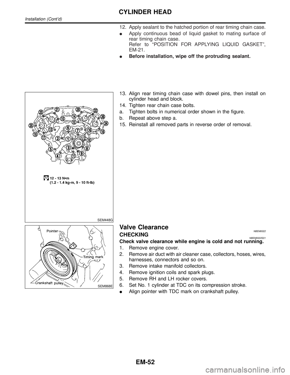
12. Apply sealant to the hatched portion of rear timing chain case.
IApply continuous bead of liquid gasket to mating surface of
rear timing chain case.
Refer to ªPOSITION FOR APPLYING LIQUID GASKETº,
EM-21.
IBefore installation, wipe off the protruding sealant.
SEM448G
13. Align rear timing chain case with dowel pins, then install on
cylinder head and block.
14. Tighten rear chain case bolts.
a. Tighten bolts in numerical order shown in the figure.
b. Repeat above step a.
15. Reinstall all removed parts in reverse order of removal.
SEM868E
Valve ClearanceNBEM0022CHECKINGNBEM0022S01Check valve clearance while engine is cold and not running.
1. Remove engine cover.
2. Remove air duct with air cleaner case, collectors, hoses, wires,
harnesses, connectors and so on.
3. Remove intake manifold collectors.
4. Remove ignition coils and spark plugs.
5. Remove RH and LH rocker covers.
6. Set No. 1 cylinder at TDC on its compression stroke.
IAlign pointer with TDC mark on crankshaft pulley.
CYLINDER HEAD
Installation (Cont'd)
EM-52
Page 1697 of 2395
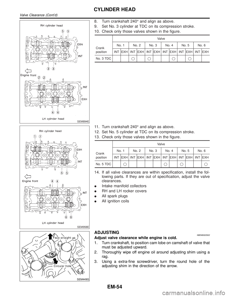
SEM894E
8. Turn crankshaft 240É and align as above.
9. Set No. 3 cylinder at TDC on its compression stroke.
10. Check only those valves shown in the figure.
Crank
positionValve
No. 1 No. 2 No. 3 No. 4 No. 5 No. 6
INT EXH INT EXH INT EXH INT EXH INT EXH INT EXH
No. 3 TDCqq qq
SEM958E
11. Turn crankshaft 240É and align as above.
12. Set No. 5 cylinder at TDC on its compression stroke.
13. Check only those valves shown in the figure.
Crank
positionValve
No. 1 No. 2 No. 3 No. 4 No. 5 No. 6
INT EXH INT EXH INT EXH INT EXH INT EXH INT EXH
No. 5 TDCqqqq
14. If all valve clearances are within specification, install the fol-
lowing parts. If they are out of specification, adjust the valve
clearances.
IIntake manifold collectors
IRH and LH rocker covers
IAll spark plugs
IAll ignition coils
SEM449G
ADJUSTINGNBEM0022S02Adjust valve clearance while engine is cold.
1. Turn crankshaft, to position cam lobe on camshaft of valve that
must be adjusted upward.
2. Thoroughly wipe off engine oil around adjusting shim using a
rag.
3. Using a extra-fine screwdriver, turn the round hole of the
adjusting shim in the direction of the arrow.
CYLINDER HEAD
Valve Clearance (Cont'd)
EM-54