Page 1561 of 2395
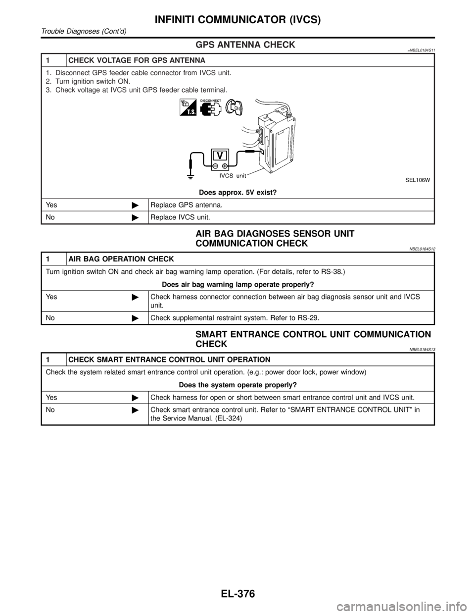
GPS ANTENNA CHECK=NBEL0184S11
1 CHECK VOLTAGE FOR GPS ANTENNA
1. Disconnect GPS feeder cable connector from IVCS unit.
2. Turn ignition switch ON.
3. Check voltage at IVCS unit GPS feeder cable terminal.
SEL106W
Does approx. 5V exist?
Ye s©Replace GPS antenna.
No©Replace IVCS unit.
AIR BAG DIAGNOSES SENSOR UNIT
COMMUNICATION CHECK
NBEL0184S12
1 AIR BAG OPERATION CHECK
Turn ignition switch ON and check air bag warning lamp operation. (For details, refer to RS-38.)
Does air bag warning lamp operate properly?
Ye s©Check harness connector connection between air bag diagnosis sensor unit and IVCS
unit.
No©Check supplemental restraint system. Refer to RS-29.
SMART ENTRANCE CONTROL UNIT COMMUNICATION
CHECK
NBEL0184S13
1 CHECK SMART ENTRANCE CONTROL UNIT OPERATION
Check the system related smart entrance control unit operation. (e.g.: power door lock, power window)
Does the system operate properly?
Ye s©Check harness for open or short between smart entrance control unit and IVCS unit.
No©Check smart entrance control unit. Refer to ªSMART ENTRANCE CONTROL UNITº in
the Service Manual. (EL-324)
INFINITI COMMUNICATOR (IVCS)
Trouble Diagnoses (Cont'd)
EL-376
Page 1565 of 2395
SEL528V
4. Touch ªBACKº key of CONSULT-II until ªSELECT SYSTEMº
appears, then turn off CONSULT-II.
5. Turn ignition switch to the OFF position.
6. Disconnect CONSULT-II DDL connector.
7. Start the engine.
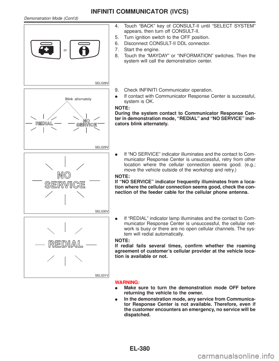
8. Touch the ªMAYDAYº or ªINFORMATIONº switches. Then the
system will call the demonstration center.
SEL529V
9. Check INFINITI Communicator operation.
IIf contact with Communicator Response Center is successful,
system is OK.
NOTE:
During the system contact to Communicator Response Cen-
ter in demonstration mode, ªREDIALº and ªNO SERVICEº indi-
cators blink alternately.
SEL530V
IIf ªNO SERVICEº indicator illuminates and the contact to Com-
municator Response Center is unsuccessful, retry from other
location where the cellular connection seems good. (e.g.;
move the vehicle outside of the workshop and retry.)
NOTE:
If ªNO SERVICEº indicator frequently illuminates from a loca-
tion where the cellular connection seems good, check the con-
nection of the feeder cable for the cellular phone antenna.
SEL531V
IIf ªREDIALº indicator lamp illuminates and the contact to Com-
municator Response Center is unsuccessful, the cellular net-
work is busy or there are no open cellular channels. The sys-
tem will redial automatically.
NOTE:
If redial fails several times, confirm whether the roaming
agreement of customer's cellular provider at the vehicle loca-
tion is available or not.
WARNING:
IMake sure to turn the demonstration mode OFF before
returning the vehicle to the owner.
IIn the demonstration mode, any service from Communica-
tor Response Center is not available. Therefore, even if
the customer encounters an emergency, no service will be
dispatched.
INFINITI COMMUNICATOR (IVCS)
Demonstration Mode (Cont'd)
EL-380
Page 1582 of 2395
Self-diagnosis ModeNBEL0231APPLICATION ITEMSNBEL0231S01
Mode DescriptionReference
page
Self DiagnosisSelf-diagnosis for display & NAVI control unit, CD-ROM
and GPS antenna connection.EL-398
Confirmation/
adjustmentDisplay Diagnosis Color and gray gradation of display can be checked in
this mode.EL-406
Diagnostic Signals from the Car Several input signals to display & NAVI control unit, can
be monitored in this mode.EL-404
NavigationCheck the map CD-
ROM versionThe version (parts number) of inserted CD-ROM can be
checked in this mode.EL-405
Error history Diagnosis results previously stored in the memory
(before turning ignition switch ON) are displayed in this
mode. Time and location when/where the errors
occurred are also displayed.EL-400
Longitude & Latitude Display the map. Use the joystick to adjust position. Lon-
gitude and latitude will be displayed.EL-407
Adjust the angle Turning angle of the vehicle on the display can be
adjusted in this mode.EL-408
Speed CalibrationUnder ordinary conditions, the navigation system dis-
tance measuring function will automatically compensate
for minute decreases in wheel and tire diameter caused
by tire wear or low pressure. Speed calibration immedi-
ately restores system accuracy in cases such as when
distance calibration is needed because of the use of tire
chains in inclement weather.EL-409
Initialize Location This mode is for initializing the current location. Use
when the vehicle is transported a long distance on a
trailer, etc.EL-433
SEL583X
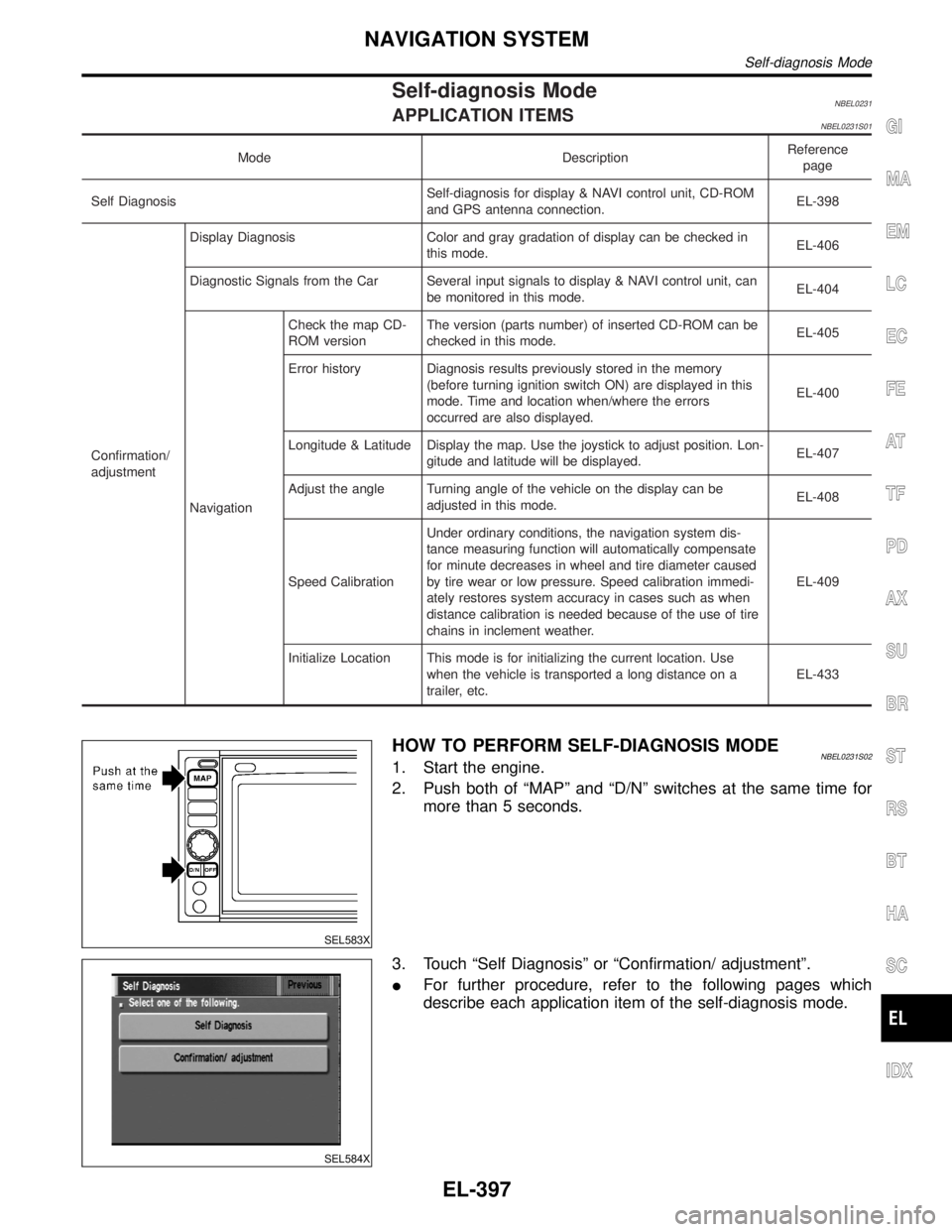
HOW TO PERFORM SELF-DIAGNOSIS MODENBEL0231S021. Start the engine.
2. Push both of ªMAPº and ªD/Nº switches at the same time for
more than 5 seconds.
SEL584X
3. Touch ªSelf Diagnosisº or ªConfirmation/ adjustmentº.
IFor further procedure, refer to the following pages which
describe each application item of the self-diagnosis mode.
GI
MA
EM
LC
EC
FE
AT
TF
PD
AX
SU
BR
ST
RS
BT
HA
SC
IDX
NAVIGATION SYSTEM
Self-diagnosis Mode
EL-397
Page 1589 of 2395
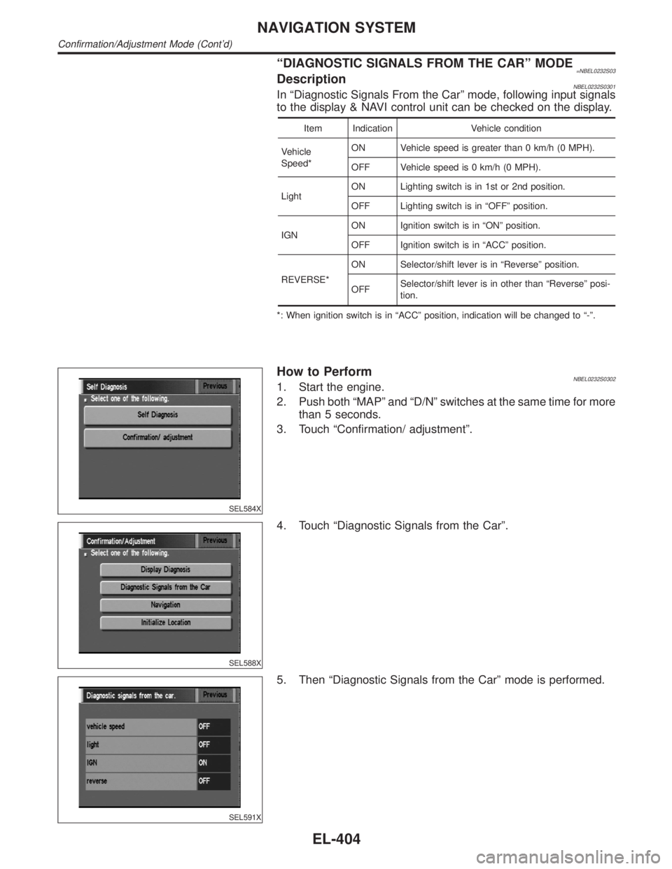
ªDIAGNOSTIC SIGNALS FROM THE CARº MODE=NBEL0232S03DescriptionNBEL0232S0301In ªDiagnostic Signals From the Carº mode, following input signals
to the display & NAVI control unit can be checked on the display.
Item Indication Vehicle condition
Vehicle
Speed*ON Vehicle speed is greater than 0 km/h (0 MPH).
OFF Vehicle speed is 0 km/h (0 MPH).
LightON Lighting switch is in 1st or 2nd position.
OFF Lighting switch is in ªOFFº position.
IGNON Ignition switch is in ªONº position.
OFF Ignition switch is in ªACCº position.
REVERSE*ON Selector/shift lever is in ªReverseº position.
OFFSelector/shift lever is in other than ªReverseº posi-
tion.
*: When ignition switch is in ªACCº position, indication will be changed to ª-º.
SEL584X
How to PerformNBEL0232S03021. Start the engine.
2. Push both ªMAPº and ªD/Nº switches at the same time for more
than 5 seconds.
3. Touch ªConfirmation/ adjustmentº.
SEL588X
4. Touch ªDiagnostic Signals from the Carº.
SEL591X
5. Then ªDiagnostic Signals from the Carº mode is performed.
NAVIGATION SYSTEM
Confirmation/Adjustment Mode (Cont'd)
EL-404
Page 1604 of 2395
DRIVING TEST=NBEL0234S03During the driving test, diagnose the system by checking the dif-
ference of symptoms with each sensor ON or OFF.
Test pattern 1
Test method in which current position adjustment is not made
according to GPS data.
IRemove the GPS antenna connector from the display & NAVI
control unit. Drive the vehicle.
Before driving the vehicle, perform ªADJUST CURRENT
LOCATIONº (EL-411).
Test pattern 2
Test procedure in which map matching is not used.
IBefore driving the vehicle, perform ªADJUST CURRENT
LOCATIONº (EL-411). With the ignition switch OFF and the
map CD-ROM removed from the display & NAVI control unit,
drive the vehicle. After driving the vehicle, reinstall the map
CD-ROM. Compare the saved driving tracks for the vehicle's
current location with roads on the map.
Example
when driving in the same area. Determine if this is the result of the
map matching function or the GPS function.>
,Perform test pattern 1.
display>
,Perform test patterns 1 and 2.
ICompare the map and the saved driving tracks. The precision
of the saved driving tracks is within several hundred meters.
,Perform test patterns 1 and 2.
IMake adjustments by driving the vehicle over a known course
(highway or other road where distances are clearly marked).
Calibrate the distance against the known distance. Use the
formula below.
Calibration value = Screen display distance/Actual distance
GI
MA
EM
LC
EC
FE
AT
TF
PD
AX
SU
BR
ST
RS
BT
HA
SC
IDX
NAVIGATION SYSTEM
Trouble diagnoses (Cont'd)
EL-419
Page 1605 of 2395
SEL693VD
POWER SUPPLY AND GROUND CIRCUIT CHECK FOR
DISPLAY & NAVI CONTROL UNIT
=NBEL0234S04Power Supply Circuit CheckNBEL0234S0401
Terminal Ignition switch
(+) (þ) OFF ACC ON
1 Ground Battery voltage Battery voltage Battery voltage
2 Ground Battery voltage Battery voltage Battery voltage
5 Ground 0V 0V Battery voltage
6 Ground 0V Battery voltage Battery voltage
If NG, check the following.
I7.5A fuse [No. 11, located in the fuse block (J/B)]
I10A fuse [No. 10, located in the fuse block (J/B)]
I15A fuse [No. 4, located in the fuse block (J/B)]
IHarness for open or short between fuse and display & NAVI
control unit
SEL694VD
Ground Circuit CheckNBEL0234S0402
Terminals Continuity
3 - Ground Yes
4 - Ground Yes
NAVIGATION SYSTEM
Trouble diagnoses (Cont'd)
EL-420
Page 1606 of 2395
VOICE GUIDE OPERATION CHECK=NBEL0234S05
1 PRELIMINARY CHECK
1. Turn ignition switch to ACC position.
2. Insert the music CD into the radio and CD player.
3. Try to play the music CD.
Is the sound emitted from all speakers?
YesorNo
Ye s©GO TO 2.
No©Repair or replace audio system.
Refer to ªAUDIOº in EL-160.
2 CHECK NAVI OPERATION ON SIGNAL
1. Disconnect audio unit connector.
2. Push ªVOICEº button.
3. Check voltage between terminal 28 and ground.
SEL645XA
OK or NG
OK©GO TO 3.
NG©Repair or replace harness or NAVI control unit.
3 CHECK VOICE SIGNAL CIRCUIT
1. Push ªVOICEº button.
2. Check voltage between NAVI control unit terminal 30 or 31 and ground.
SEL648X
OK or NG
OK©GO TO 4.
NG©Repair or replace NAVI control unit.
GI
MA
EM
LC
EC
FE
AT
TF
PD
AX
SU
BR
ST
RS
BT
HA
SC
IDX
NAVIGATION SYSTEM
Trouble diagnoses (Cont'd)
EL-421
Page 1607 of 2395
4 CHECK VOICE SIGNAL CIRCUIT
1. Turn ignition switch OFF.
2. Disconnect NAVI control unit connector and AUDIO unit connector.
3. Check continuity between NAVI control unit terminal 30 and AUDIO unit terminal 36.
4. Check continuity between NAVI control unit terminal 31 and AUDIO unit terminal 34.
SEL649X
YesorNo
Ye s©Repair or replace audio system.
Refer to ªAUDIOº in EL-160.
No©Repair or replace harness or connector.
NAVIGATION SYSTEM
Trouble diagnoses (Cont'd)
EL-422