2001 INFINITI QX4 ignition
[x] Cancel search: ignitionPage 1781 of 2395
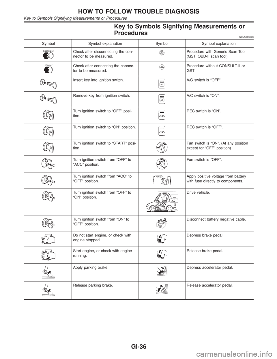
Key to Symbols Signifying Measurements or
Procedures
NBGI0005S02
Symbol Symbol explanation Symbol Symbol explanation
Check after disconnecting the con-
nector to be measured.Procedure with Generic Scan Tool
(GST, OBD-II scan tool)
Check after connecting the connec-
tor to be measured.Procedure without CONSULT-II or
GST
Insert key into ignition switch.A/C switch is ªOFFº.
Remove key from ignition switch.A/C switch is ªONº.
Turn ignition switch to ªOFFº posi-
tion.REC switch is ªONº.
Turn ignition switch to ªONº position.REC switch is ªOFFº.
Turn ignition switch to ªSTARTº posi-
tion.Fan switch is ªONº. (At any position
except for ªOFFº position)
Turn ignition switch from ªOFFº to
ªACCº position.Fan switch is ªOFFº.
Turn ignition switch from ªACCº to
ªOFFº position.Apply positive voltage from battery
with fuse directly to components.
Turn ignition switch from ªOFFº to
ªONº position.Drive vehicle.
Turn ignition switch from ªONº to
ªOFFº position.Disconnect battery negative cable.
Do not start engine, or check with
engine stopped.Depress brake pedal.
Start engine, or check with engine
running.Release brake pedal.
Apply parking brake.Depress accelerator pedal.
Release parking brake.Release accelerator pedal.
HOW TO FOLLOW TROUBLE DIAGNOSIS
Key to Symbols Signifying Measurements or Procedures
GI-36
Page 1783 of 2395
NBGI0006
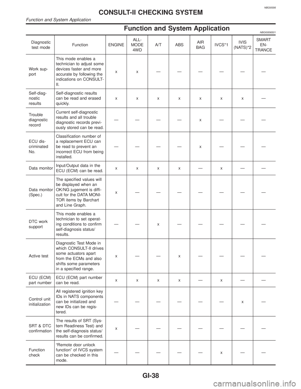
Function and System ApplicationNBGI0006S01
Diagnostic
test modeFunction ENGINEALL-
MODE
4WDA/T ABSAIR
BAGIVCS*1IVIS
(NATS)*2SMART
EN-
TRANCE
Work sup-
portThis mode enables a
technician to adjust some
devices faster and more
accurate by following the
indications on CONSULT-
II.x x ÐÐÐÐÐÐ
Self-diag-
nostic
resultsSelf-diagnostic results
can be read and erased
quickly.xxxxxxxÐ
Trouble
diagnostic
recordCurrent self-diagnostic
results and all trouble
diagnostic records previ-
ously stored can be read.ÐÐÐÐ x ÐÐÐ
ECU dis-
criminated
No.Classification number of
a replacement ECU can
be read to prevent an
incorrect ECU from being
installed.ÐÐÐÐ x ÐÐÐ
Data monitorInput/Output data in the
ECU (ECM) can be read.x x x xÐxÐÐ
Data monitor
(Spec.)The specified values will
be displayed when an
OK/NG jugement is diffi-
cult for the DATA MONI-
TOR items by Barchart
and Line Graph.x ÐÐÐÐÐÐÐ
DTC work
supportThis mode enables a
technician to set operat-
ing conditions to confirm
self-diagnosis status/
results.ÐÐ x ÐÐÐÐÐ
Active testDiagnostic Test Mode in
which CONSULT-II drives
some actuators apart
from the ECMs and also
shifts some parameters
in a specified range.x ÐÐ x ÐÐÐÐ
ECU (ECM)
part numberECU (ECM) part number
can be read.x x x xÐxÐÐ
Control unit
initializationAll registered ignition key
IDs in NATS components
can be initialized and
new IDs can be regis-
tered.ÐÐÐÐÐÐ x Ð
SRT & DTC
confirmationThe results of SRT (Sys-
tem Readiness Test) and
the self-diagnosis status/
results can be confirmed.x ÐÐÐÐÐÐÐ
Function
checkªRemote door unlock
functionº of IVCS system
can be checked in this
mode.ÐÐÐÐÐ x ÐÐ
CONSULT-II CHECKING SYSTEM
Function and System Application
GI-38
Page 1793 of 2395
SGI989
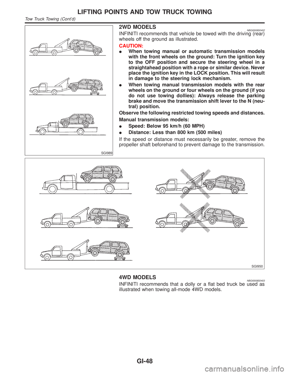
2WD MODELSNBGI0008S0402INFINITI recommends that vehicle be towed with the driving (rear)
wheels off the ground as illustrated.
CAUTION:
IWhen towing manual or automatic transmission models
with the front wheels on the ground: Turn the ignition key
to the OFF position and secure the steering wheel in a
straightahead position with a rope or similar device. Never
place the ignition key in the LOCK position. This will result
in damage to the steering lock mechanism.
IWhen towing manual transmission models with the rear
wheels on the ground or four wheels on the ground (if you
do not use towing dollies): Always release the parking
brake and move the transmission shift lever to the N (neu-
tral) position.
Observe the following restricted towing speeds and distances.
Manual transmission models:
ISpeed: Below 95 km/h (60 MPH)
IDistance: Less than 800 km (500 miles)
If the speed or distance must necessarily be greater, remove the
propeller shaft beforehand to prevent damage to the transmission.
SGI950
4WD MODELSNBGI0008S0403INFINITI recommends that a dolly or a flat bed truck be used as
illustrated when towing all-mode 4WD models.
LIFTING POINTS AND TOW TRUCK TOWING
Tow Truck Towing (Cont'd)
GI-48
Page 1796 of 2395
NBGI0010
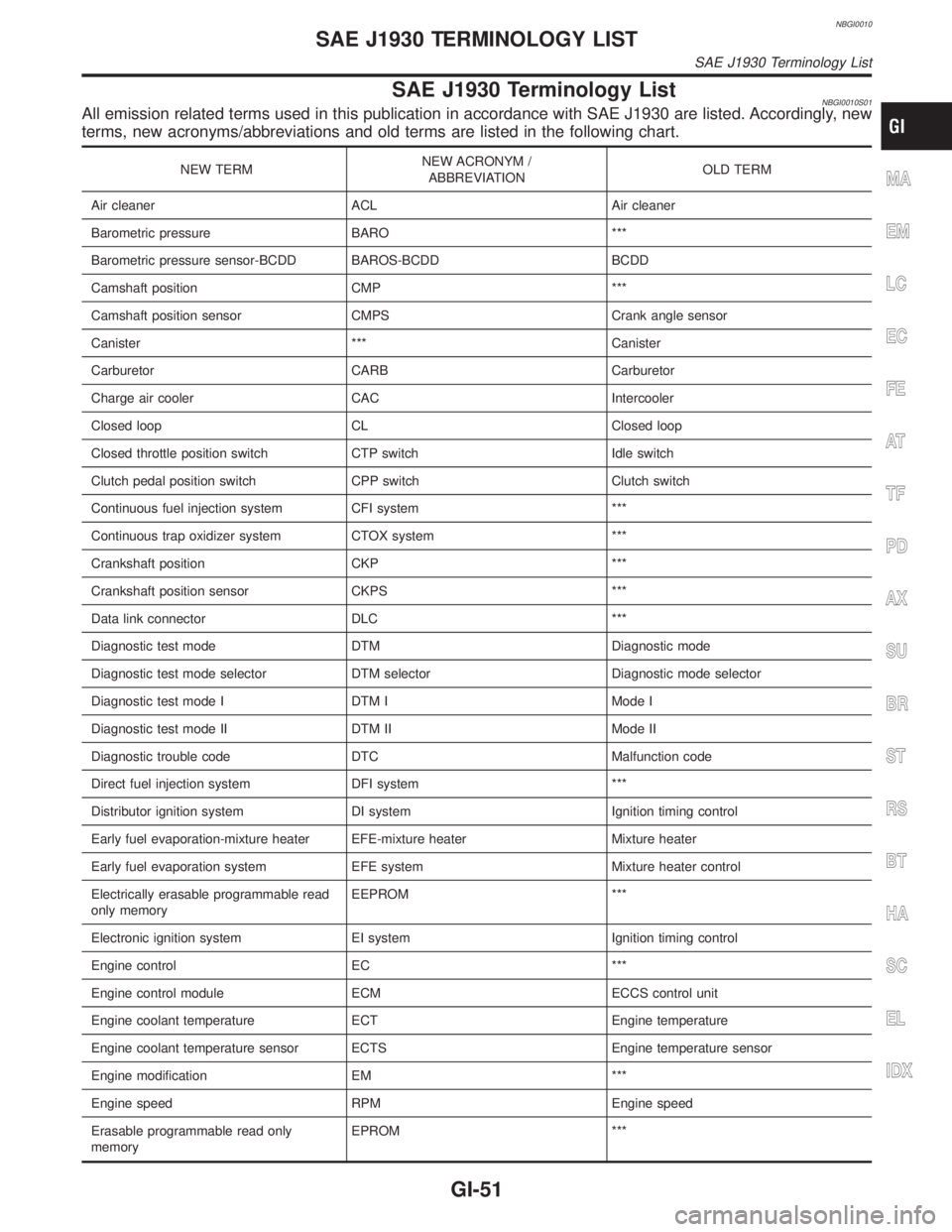
SAE J1930 Terminology ListNBGI0010S01All emission related terms used in this publication in accordance with SAE J1930 are listed. Accordingly, new
terms, new acronyms/abbreviations and old terms are listed in the following chart.
NEW TERMNEW ACRONYM /
ABBREVIATIONOLD TERM
Air cleaner ACL Air cleaner
Barometric pressure BARO ***
Barometric pressure sensor-BCDD BAROS-BCDD BCDD
Camshaft position CMP ***
Camshaft position sensor CMPS Crank angle sensor
Canister *** Canister
Carburetor CARB Carburetor
Charge air cooler CAC Intercooler
Closed loop CL Closed loop
Closed throttle position switch CTP switch Idle switch
Clutch pedal position switch CPP switch Clutch switch
Continuous fuel injection system CFI system ***
Continuous trap oxidizer system CTOX system ***
Crankshaft position CKP ***
Crankshaft position sensor CKPS ***
Data link connector DLC ***
Diagnostic test mode DTM Diagnostic mode
Diagnostic test mode selector DTM selector Diagnostic mode selector
Diagnostic test mode I DTM I Mode I
Diagnostic test mode II DTM II Mode II
Diagnostic trouble code DTC Malfunction code
Direct fuel injection system DFI system ***
Distributor ignition system DI system Ignition timing control
Early fuel evaporation-mixture heater EFE-mixture heater Mixture heater
Early fuel evaporation system EFE system Mixture heater control
Electrically erasable programmable read
only memoryEEPROM ***
Electronic ignition system EI system Ignition timing control
Engine control EC ***
Engine control module ECM ECCS control unit
Engine coolant temperature ECT Engine temperature
Engine coolant temperature sensor ECTS Engine temperature sensor
Engine modification EM ***
Engine speed RPM Engine speed
Erasable programmable read only
memoryEPROM ***MA
EM
LC
EC
FE
AT
TF
PD
AX
SU
BR
ST
RS
BT
HA
SC
EL
IDX
SAE J1930 TERMINOLOGY LIST
SAE J1930 Terminology List
GI-51
Page 1797 of 2395
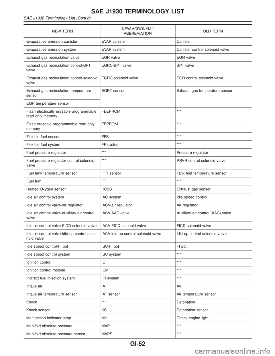
NEW TERMNEW ACRONYM /
ABBREVIATIONOLD TERM
Evaporative emission canister EVAP canister Canister
Evaporative emission system EVAP system Canister control solenoid valve
Exhaust gas recirculation valve EGR valve EGR valve
Exhaust gas recirculation control-BPT
valveEGRC-BPT valve BPT valve
Exhaust gas recirculation control-solenoid
valveEGRC-solenoid valve EGR control solenoid valve
Exhaust gas recirculation temperature
sensorEGRT sensor Exhaust gas temperature sensor
EGR temperature sensor
Flash electrically erasable programmable
read only memoryFEEPROM ***
Flash erasable programmable read only
memoryFEPROM ***
Flexible fuel sensor FFS ***
Flexible fuel system FF system ***
Fuel pressure regulator *** Pressure regulator
Fuel pressure regulator control solenoid
valve*** PRVR control solenoid valve
Fuel tank temperature sensor FTT sensor Tank fuel temperature sensor
Fuel trim FT ***
Heated Oxygen sensor HO2S Exhaust gas sensor
Idle air control system IAC system Idle speed control
Idle air control valve-air regulator IACV-air regulator Air regulator
Idle air control valve-auxiliary air control
valveIACV-AAC valve Auxiliary air control (AAC) valve
Idle air control valve-FICD solenoid valve IACV-FICD solenoid valve FICD solenoid valve
Idle air control valve-idle up control sole-
noid valveIACV-idle up control solenoid valve Idle up control solenoid valve
Idle speed control-FI pot ISC-FI pot FI pot
Idle speed control system ISC system ***
Ignition control IC ***
Ignition control module ICM ***
Indirect fuel injection system IFI system ***
Intake air IA Air
Intake air temperature sensor IAT sensor Air temperature sensor
Knock *** Detonation
Knock sensor KS Detonation sensor
Malfunction indicator lamp MIL Check engine light
Manifold absolute pressure MAP ***
Manifold absolute pressure sensor MAPS ***
SAE J1930 TERMINOLOGY LIST
SAE J1930 Terminology List (Cont'd)
GI-52
Page 1814 of 2395
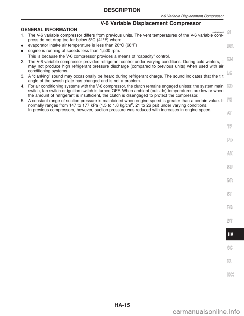
V-6 Variable Displacement Compressor
GENERAL INFORMATION=NBHA00861. The V-6 variable compressor differs from previous units. The vent temperatures of the V-6 variable com-
press do not drop too far below 5ÉC (41ÉF) when:
Ievaporator intake air temperature is less than 20ÉC (68ÉF)
Iengine is running at speeds less than 1,500 rpm.
This is because the V-6 compressor provides a means of ªcapacityº control.
2. The V-6 variable compressor provides refrigerant control under varying conditions. During cold winters, it
may not produce high refrigerant pressure discharge (compared to previous units) when used with air
conditioning systems.
3. A ªclankingº sound may occasionally be heard during refrigerant charge. The sound indicates that the tilt
angle of the swash plate has changed and is not a problem.
4. For air conditioning systems with the V-6 compressor, the clutch remains engaged unless: the system main
switch, fan switch or ignition switch is turned OFF. When ambient (outside) temperatures are low or when
the amount of refrigerant is insufficient, the clutch is disengaged to protect the compressor.
5. A constant range of suction pressure is maintained when engine speed is greater than a certain value. It
normally ranges from 147 to 177 kPa (1.5 to 1.8 kg/cm
2, 21 to 26 psi) under varying conditions.
In previous compressors, however, suction pressure was reduced with increases in engine speed.
GI
MA
EM
LC
EC
FE
AT
TF
PD
AX
SU
BR
ST
RS
BT
SC
EL
IDX
DESCRIPTION
V-6 Variable Displacement Compressor
HA-15
Page 1840 of 2395
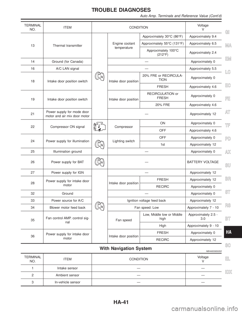
TERMINAL
NO.ITEM CONDITIONVoltage
V
13 Thermal transmitter
Engine coolant
temperatureApproximately 30ÉC (86ÉF) Approximately 9.4
Approximately 55ÉC (131ÉF) Approximately 6.5
Approximately 100ÉC
(212ÉF)Approximately 2.4
14 Ground (for Canada) Ð Approximately 0
16 A/C LAN signal Ð Approximately 5.5
18 Intake door position switch Intake door position20% FRE or RECIRCULA-
TIONApproximately 0
FRESH Approximately 4.6
19 Intake door position switch Intake door positionRECIRCULATION or
FRESHApproximately 0
20% FRE Approximately 4.6
21Power supply for mode door
motor and air mix door motorÐ Approximately 12
22 Compressor ON signal
CompressorON Approximately 0
OFF Approximately 4.6
24 Power supply for illumination
Lighting switchOFF Approximately 0
1st Approximately 12
25 Illumination ground Ð Approximately 0
26 Power supply for BAT
Ð BATTERY VOLTAGE
27 Power supply for IGN
Ð Approximately 12
28Power supply for intake door
motorIntake door positionFRESH Approximately 12
RECIRC Approximately 0
32 Ground Ð Approximately 0
33 Power source for A/C Ignition voltage feed back Approximately 12
34 Blower motor feed back Fan speed: Low Approximately7-10
35Fan control AMP. control sig-
nalFan speedLow, Middle low or Middle
highApproximately 2.5 -
3.0
High Approximately9-10
36Power supply for intake door
motorIntake door positionFRESH Approximately 0
RECIRC Approximately 12
With Navigation SystemNBHA0036S0202
TERMINAL
NO.ITEM CONDITIONVoltage
V
1 Intake sensor Ð Ð
2 Ambient sensor Ð Ð
3 In-vehicle sensor Ð Ð
GI
MA
EM
LC
EC
FE
AT
TF
PD
AX
SU
BR
ST
RS
BT
SC
EL
IDX
TROUBLE DIAGNOSES
Auto Amp. Terminals and Reference Value (Cont'd)
HA-41
Page 1843 of 2395

Self-diagnosis=NBHA0021INTRODUCTION AND GENERAL DESCRIPTIONNBHA0021S01The self-diagnostic system diagnoses sensors, door motors, blower motor, etc. by system line. Refer to appli-
cable sections (items) for details. Shifting from normal control to the self-diagnostic system is accomplished
by starting the engine (turning the ignition switch from ªOFFº to ªONº) and pressing ª
º switch for at least
5 seconds. The ª
º switch must be pressed within 10 seconds after starting the engine (ignition switch is
turned ªONº). This system will be canceled by either pressing
(AUTO) switch or turning the ignition switch
ªOFFº. Shifting from one step to another is accomplished by means of pushing
(HOT) or(COLD) switch,
as required.
Additionally shifting from STEP 5 to AUXILIARY MECHANISM is accomplished by means of pushing
(fan)
UP switch.
Without Navigation SystemNBHA0021S0101
RHA453GA
TROUBLE DIAGNOSES
Self-diagnosis
HA-44