Page 1126 of 2395
SEF485T
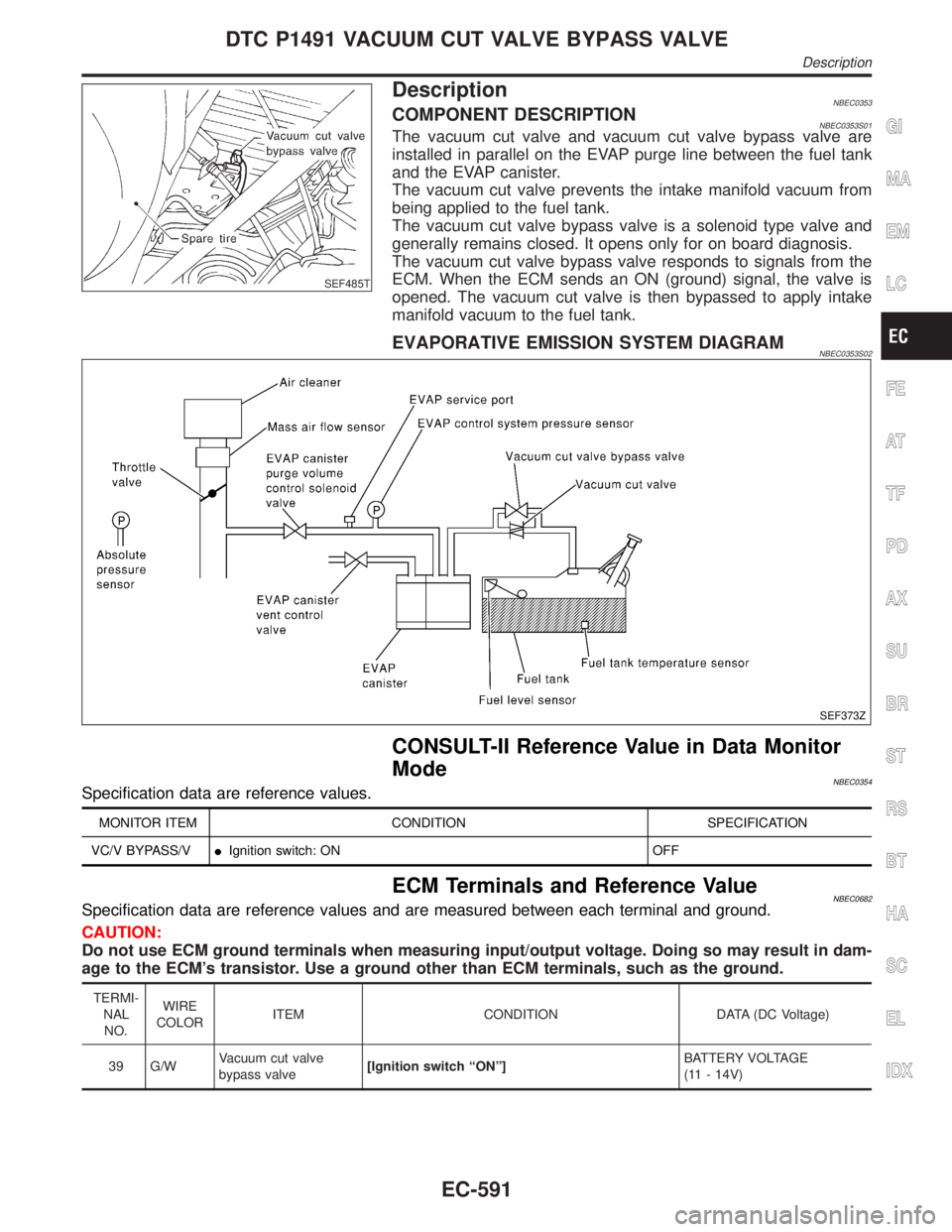
DescriptionNBEC0353COMPONENT DESCRIPTIONNBEC0353S01The vacuum cut valve and vacuum cut valve bypass valve are
installed in parallel on the EVAP purge line between the fuel tank
and the EVAP canister.
The vacuum cut valve prevents the intake manifold vacuum from
being applied to the fuel tank.
The vacuum cut valve bypass valve is a solenoid type valve and
generally remains closed. It opens only for on board diagnosis.
The vacuum cut valve bypass valve responds to signals from the
ECM. When the ECM sends an ON (ground) signal, the valve is
opened. The vacuum cut valve is then bypassed to apply intake
manifold vacuum to the fuel tank.
EVAPORATIVE EMISSION SYSTEM DIAGRAMNBEC0353S02
SEF373Z
CONSULT-II Reference Value in Data Monitor
Mode
NBEC0354Specification data are reference values.
MONITOR ITEM CONDITION SPECIFICATION
VC/V BYPASS/VIIgnition switch: ON OFF
ECM Terminals and Reference ValueNBEC0682Specification data are reference values and are measured between each terminal and ground.
CAUTION:
Do not use ECM ground terminals when measuring input/output voltage. Doing so may result in dam-
age to the ECM's transistor. Use a ground other than ECM terminals, such as the ground.
TERMI-
NAL
NO.WIRE
COLORITEM CONDITION DATA (DC Voltage)
39 G/WVacuum cut valve
bypass valve[Ignition switch ªONº]BATTERY VOLTAGE
(11 - 14V)
GI
MA
EM
LC
FE
AT
TF
PD
AX
SU
BR
ST
RS
BT
HA
SC
EL
IDX
DTC P1491 VACUUM CUT VALVE BYPASS VALVE
Description
EC-591
Page 1139 of 2395
AEC877A
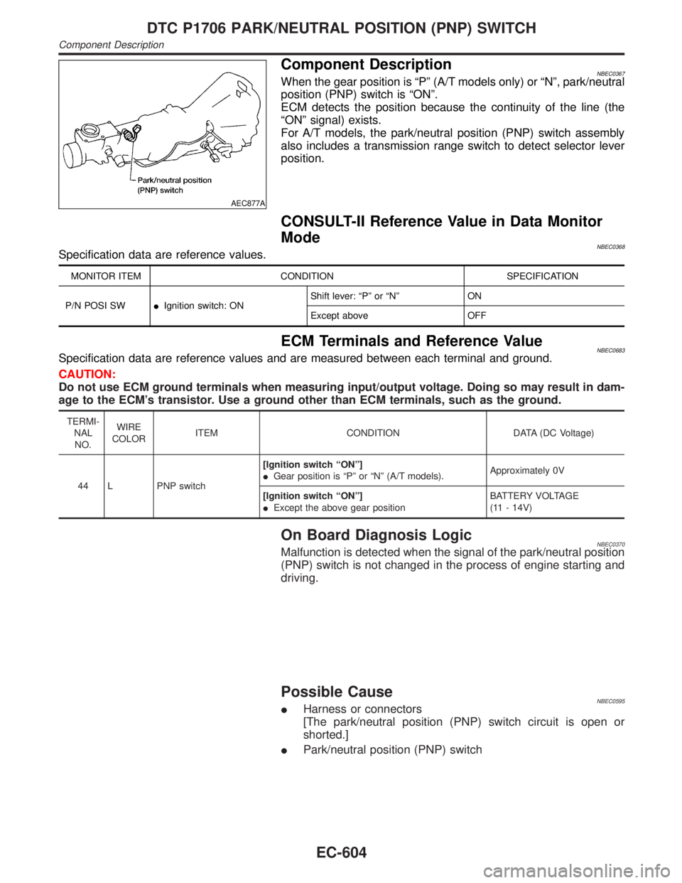
Component DescriptionNBEC0367When the gear position is ªPº (A/T models only) or ªNº, park/neutral
position (PNP) switch is ªONº.
ECM detects the position because the continuity of the line (the
ªONº signal) exists.
For A/T models, the park/neutral position (PNP) switch assembly
also includes a transmission range switch to detect selector lever
position.
CONSULT-II Reference Value in Data Monitor
Mode
NBEC0368Specification data are reference values.
MONITOR ITEM CONDITION SPECIFICATION
P/N POSI SWIIgnition switch: ONShift lever: ªPº or ªNº ON
Except above OFF
ECM Terminals and Reference ValueNBEC0683Specification data are reference values and are measured between each terminal and ground.
CAUTION:
Do not use ECM ground terminals when measuring input/output voltage. Doing so may result in dam-
age to the ECM's transistor. Use a ground other than ECM terminals, such as the ground.
TERMI-
NAL
NO.WIRE
COLORITEM CONDITION DATA (DC Voltage)
44 L PNP switch[Ignition switch ªONº]
IGear position is ªPº or ªNº (A/T models).Approximately 0V
[Ignition switch ªONº]
IExcept the above gear positionBATTERY VOLTAGE
(11 - 14V)
On Board Diagnosis LogicNBEC0370Malfunction is detected when the signal of the park/neutral position
(PNP) switch is not changed in the process of engine starting and
driving.
Possible CauseNBEC0595IHarness or connectors
[The park/neutral position (PNP) switch circuit is open or
shorted.]
IPark/neutral position (PNP) switch
DTC P1706 PARK/NEUTRAL POSITION (PNP) SWITCH
Component Description
EC-604
Page 1156 of 2395
CONSULT-II Reference Value in Data Monitor
Mode
NBEC0388Specification data are reference values.
MONITOR ITEM CONDITION SPECIFICATION
START SIGNALIIgnition switch: ON,START,ON OFF,ON,OFF
ECM Terminals and Reference ValueNBEC0688Specification data are reference values and are measured between each terminal and ground.
CAUTION:
Do not use ECM ground terminals when measuring input/output voltage. Doing so may result in dam-
age to the ECM's transistor. Use a ground other than ECM terminals, such as the ground.
TERMI-
NAL
NO.WIRE
COLORITEM CONDITION DATA (DC Voltage)
42 B/Y Start signal[Ignition switch ªONº]Approximately 0V
[Ignition switch ªSTARTº]9 - 12V
GI
MA
EM
LC
FE
AT
TF
PD
AX
SU
BR
ST
RS
BT
HA
SC
EL
IDX
START SIGNAL
CONSULT-II Reference Value in Data Monitor Mode
EC-621
Page 1161 of 2395
ECM Terminals and Reference Value=NBEC0686Specification data are reference values and are measured between each terminal and ground.
CAUTION:
Do not use ECM ground terminals when measuring input/output voltage. Doing so may result in dam-
age to the ECM's transistor. Use a ground other than ECM terminals, such as the ground.
TERMI-
NAL
NO.WIRE
COLORITEM CONDITION DATA (DC Voltage)
28 R/L Fuel pump relay[Ignition switch ªONº]
IFor 1 second after turning ignition switch ªONº
[Engine is running]0 - 1.5V
[Ignition switch ªONº]
I1 second passed after turning ignition switch
ªONº.BATTERY VOLTAGE
(11 - 14V)
FUEL PUMP
ECM Terminals and Reference Value
EC-626
Page 1174 of 2395
SEF029Z
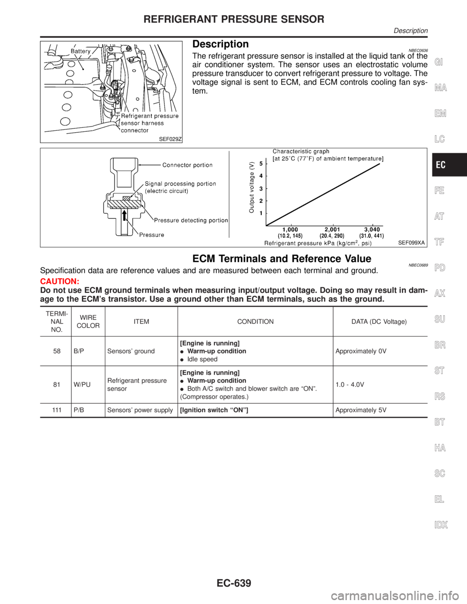
DescriptionNBEC0636The refrigerant pressure sensor is installed at the liquid tank of the
air conditioner system. The sensor uses an electrostatic volume
pressure transducer to convert refrigerant pressure to voltage. The
voltage signal is sent to ECM, and ECM controls cooling fan sys-
tem.
SEF099XA
ECM Terminals and Reference ValueNBEC0689Specification data are reference values and are measured between each terminal and ground.
CAUTION:
Do not use ECM ground terminals when measuring input/output voltage. Doing so may result in dam-
age to the ECM's transistor. Use a ground other than ECM terminals, such as the ground.
TERMI-
NAL
NO.WIRE
COLORITEM CONDITION DATA (DC Voltage)
58 B/P Sensors' ground[Engine is running]
IWarm-up condition
IIdle speedApproximately 0V
81 W/PURefrigerant pressure
sensor[Engine is running]
IWarm-up condition
IBoth A/C switch and blower switch are ªONº.
(Compressor operates.)1.0 - 4.0V
111 P/B Sensors' power supply[Ignition switch ªONº]Approximately 5V
GI
MA
EM
LC
FE
AT
TF
PD
AX
SU
BR
ST
RS
BT
HA
SC
EL
IDX
REFRIGERANT PRESSURE SENSOR
Description
EC-639
Page 1227 of 2395
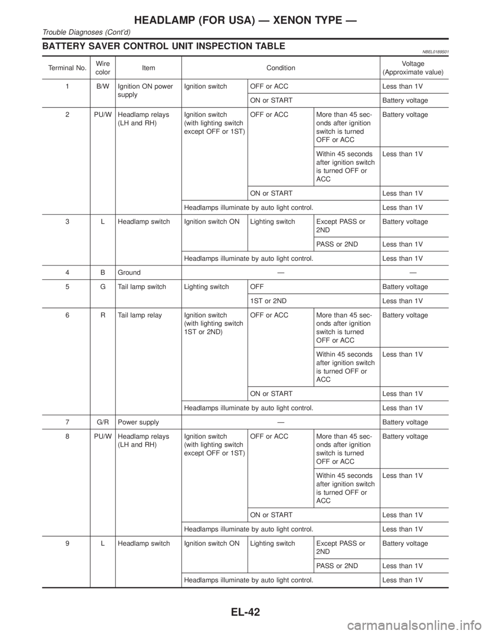
BATTERY SAVER CONTROL UNIT INSPECTION TABLENBEL0189S01
Terminal No.Wire
colorItem ConditionVoltage
(Approximate value)
1 B/W Ignition ON power
supplyIgnition switch OFF or ACC Less than 1V
ON or START Battery voltage
2 PU/W Headlamp relays
(LH and RH)Ignition switch
(with lighting switch
except OFF or 1ST)OFF or ACC More than 45 sec-
onds after ignition
switch is turned
OFF or ACCBattery voltage
Within 45 seconds
after ignition switch
is turned OFF or
ACCLess than 1V
ON or START Less than 1V
Headlamps illuminate by auto light control. Less than 1V
3 L Headlamp switch Ignition switch ON Lighting switch Except PASS or
2NDBattery voltage
PASS or 2ND Less than 1V
Headlamps illuminate by auto light control. Less than 1V
4 B Ground Ð Ð
5 G Tail lamp switch Lighting switch OFF Battery voltage
1ST or 2ND Less than 1V
6 R Tail lamp relay Ignition switch
(with lighting switch
1ST or 2ND)OFF or ACC More than 45 sec-
onds after ignition
switch is turned
OFF or ACCBattery voltage
Within 45 seconds
after ignition switch
is turned OFF or
ACCLess than 1V
ON or START Less than 1V
Headlamps illuminate by auto light control. Less than 1V
7 G/R Power supply Ð Battery voltage
8 PU/W Headlamp relays
(LH and RH)Ignition switch
(with lighting switch
except OFF or 1ST)OFF or ACC More than 45 sec-
onds after ignition
switch is turned
OFF or ACCBattery voltage
Within 45 seconds
after ignition switch
is turned OFF or
ACCLess than 1V
ON or START Less than 1V
Headlamps illuminate by auto light control. Less than 1V
9 L Headlamp switch Ignition switch ON Lighting switch Except PASS or
2NDBattery voltage
PASS or 2ND Less than 1V
Headlamps illuminate by auto light control. Less than 1V
HEADLAMP (FOR USA) Ð XENON TYPE Ð
Trouble Diagnoses (Cont'd)
EL-42
Page 1228 of 2395
Terminal No.Wire
colorItem ConditionVoltage
(Approximate value)
10 R/Y RAP signal Ignition switch OFF or ACC
(After more than 45 seconds with ignition
switch turned OFF or ACC)Less than 1V
ON or START Battery voltage
11 B Ground Ð Ð
13 G Tail lamp switch Lighting switch OFF Battery voltage
1ST or 2ND Less than 1V
14 R Tail lamp relay Ignition switch
(with lighting switch
1ST or 2ND)OFF or ACC More than 45 sec-
onds after ignition
switch is turned
OFF or ACCBattery voltage
Within 45 seconds
after ignition switch
is turned OFF or
ACCLess than 1V
ON or START Less than 1V
Headlamps illuminate by auto light control. Less than 1V
Bulb Replacement/Xenon TypeNBEL0190CAUTION:
IAfter replacing a new xenon bulb, be sure to make aiming
adjustments.
IHold only the plastic base when handling the bulb. Never
touch the glass envelope.
IDo not leave headlamp reflector without bulb for a long
period of time. Dust, moisture, smoke, etc. entering head-
lamp body may affect the performance of the headlamp.
Remove headlamp bulb from the headlamp reflector just
before a replacement bulb is installed.
1. Disconnect negative battery cable.
2. Disconnect headlamp connector.
3. Remove headlamp assembly.
WARNING:
Never service a xenon headlamp without disconnecting nega-
tive battery cable and with wet hands.
SEL349X
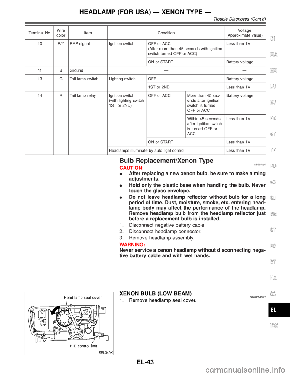
XENON BULB (LOW BEAM)NBEL0190S011. Remove headlamp seal cover.
GI
MA
EM
LC
EC
FE
AT
TF
PD
AX
SU
BR
ST
RS
BT
HA
SC
IDX
HEADLAMP (FOR USA) Ð XENON TYPE Ð
Trouble Diagnoses (Cont'd)
EL-43
Page 1233 of 2395
BATTERY SAVER CONTROLNBEL0192S02When the ignition switch is turned from ON (or START) to OFF (or ACC) positions while headlamps are
illuminated, The RAP signal is supplied to terminal 10 of the headlamp battery saver control unit from smart
entrance control unit terminal 5.
After counting 45 seconds by the RAP signal from the smart entrance control unit to headlamp battery saver
control unit, the ground supply to terminal 2 of headlamp LH and RH relays from headlamp battery saver con-
trol unit terminals 2 and 8 is terminated.
Then headlamps are turned off.
The headlamps are turned off when LH or RH door is opened even if 45 seconds have not passed after the
ignition switch is turned from ON (or START) to OFF (or ACC) positions while headlamps are illuminated.
When the lighting switch is turned from OFF to 2ND after headlamps are turned to off by the battery saver
control, ground is supply
Ito headlamp battery saver control unit terminals 5 and 13 from lighting switch terminal 11, and
Ito headlamp LH and RH relays terminal 2 from headlamp battery saver control unit terminals 2 and 8
Ithrough headlamp battery saver control unit terminals 3 and 9, and
Ithrough lighting switch terminal 12.
Then headlamps illuminate again.
AUTO LIGHT OPERATIONNBEL0192S03For auto light operation, refer to ªHEADLAMPº (EL-33).
DAYTIME LIGHT OPERATIONNBEL0192S04With the engine running, the lighting switch in the OFF or 1ST position and parking brake released, power is
supplied
Ithrough daytime light control unit terminals 3 and 7
Ito terminal 1 of RH headlamp
Ithrough terminal 2 of RH headlamp
Ito daytime light control unit terminal 9
Ithrough daytime light control unit terminal 6
Ito terminal 1 of LH headlamp.
Ground is supplied to terminal 2 of LH headlamp.
Ithrough daytime light control unit terminals 10 and 16
Ithrough body grounds E13 and E41.
Because the high beam headlamps are now wired in series, they operate at half illumination.
HEADLAMP (FOR CANADA) Ð DAYTIME LIGHT SYSTEM Ð
System Description (Cont'd)
EL-48