2001 INFINITI QX4 ignition wire
[x] Cancel search: ignition wirePage 916 of 2395

SEF053V
SEF954S
Component DescriptionNBEC0235The EVAP control system pressure sensor detects pressure in the
purge line. The sensor output voltage to the ECM increases as
pressure increases. The EVAP control system pressure sensor is
not used to control the engine system. It is used only for on board
diagnosis.
CONSULT-II Reference Value in Data Monitor
Mode
NBEC0236Specification data are reference values.
MONITOR ITEM CONDITION SPECIFICATION
EVAP SYS PRESIIgnition switch: ON Approx. 3.4V
ECM Terminals and Reference ValueNBEC0668Specification data are reference values and are measured between each terminal and ground.
CAUTION:
Do not use ECM ground terminals when measuring input/output voltage. Doing so may result in dam-
age to the ECM's transistor. Use a ground other than ECM terminals, such as the ground.
TERMI-
NAL
NO.WIRE
COLORITEM CONDITION DATA (DC Voltage)
58 B/P Sensors' ground[Engine is running]
IWarm-up condition
IIdle speedApproximately 0V
84 L/GEVAP control system
pressure sensor[Ignition switch ªONº]Approximately 3.4V
111 P/B Sensors' power supply[Ignition switch ªONº]Approximately 5V
GI
MA
EM
LC
FE
AT
TF
PD
AX
SU
BR
ST
RS
BT
HA
SC
EL
IDX
DTC P0450 EVAPORATIVE EMISSION (EVAP) CONTROL SYSTEM PRESSURE
SENSOR
Component Description
EC-381
Page 958 of 2395

CONSULT-II Reference Value in Data Monitor
Mode
NBEC0250Specification data are reference values.
MONITOR ITEM CONDITION SPECIFICATION
IACV-AAC/VIEngine: After warming up
IAir conditioner switch: ªOFFº
IShift lever: ªNº
INo-loadIdle 14 - 20 step
2,000 rpm Ð
ECM Terminals and Reference ValueNBEC0670Specification data are reference values and are measured between each terminal and ground.
CAUTION:
Do not use ECM ground terminals when measuring input/output voltage. Doing so may result in dam-
age to the ECM's transistor. Use a ground other than ECM terminals, such as the ground.
TERMI-
NAL
NO.WIRE
COLORITEM CONDITION DATA (DC Voltage)
6
7
8
17PU/G
GY
Y
GY/LIACV-AAC valve[Engine is running]
IIdle speed0.1 - 14V
On Board Diagnosis LogicNBEC0252Malfunction is detected when
(Malfunction A)the IACV-AAC valve does not operate properly,
(Malfunction B)the IACV-AAC valve does not operate properly.
Possible CauseNBEC0515MALFUNCTION ANBEC0515S01IHarness or connectors
(The IACV-AAC valve circuit is open.)
IIACV-AAC valve
MALFUNCTION BNBEC0515S02IHarness or connectors
(The IACV-AAC valve circuit is shorted.)
IAir control valve (Power steering)
IIACV-AAC valve
DTC Confirmation ProcedureNBEC0253NOTE:
IIf ªDTC Confirmation Procedureº has been previously
conducted, always turn ignition switch ªOFFº and wait at least
10 seconds before conducting the next test.
IPerform ªPROCEDURE FOR MALFUNCTION Aº first. If 1st
trip DTC cannot be confirmed, perform ªPROCEDURE
FOR MALFUNCTION Bº.
GI
MA
EM
LC
FE
AT
TF
PD
AX
SU
BR
ST
RS
BT
HA
SC
EL
IDX
DTC P0505 IDLE AIR CONTROL VALVE (IACV) Ð AUXILIARY AIR CONTROL
(AAC) VALVE
CONSULT-II Reference Value in Data Monitor Mode
EC-423
Page 975 of 2395

System DescriptionNBEC0264This circuit line (LAN) is used to control the smooth shifting up and down of A/T during the hard acceleration/
deceleration.
Pulse signals are exchanged between ECM and TCM (Transmission Control Module).
Be sure to erase the malfunction information such as DTC not only in TCM but also ECM after the A/T
related repair.
ECM Terminals and Reference ValueNBEC0672Specification data are reference values and are measured between each terminal and ground.
CAUTION:
Do not use ECM ground terminals when measuring input/output voltage. Doing so may result in dam-
age to the ECM's transistor. Use a ground other than ECM terminals, such as the ground.
TERMI-
NAL
NO.WIRE
COLORITEM CONDITION DATA (DC Voltage)
114 G/RCommunication line
(LAN)[Engine is running]
IIdle speedApproximately 2V
On Board Diagnosis LogicNBEC0266Malfunction is detected when ECM receives incorrect voltage from
TCM (Transmission Control Module) continuously.
Possible CauseNBEC0517IHarness or connectors
[The communication line circuit between ECM and TCM
(Transmission Control Module) is open or shorted.]
ITCM
IDead (Weak) battery
SEF058Y
DTC Confirmation ProcedureNBEC0267NOTE:
If ªDTC Confirmation Procedureº has been previously conducted,
always turn ignition switch ªOFFº and wait at least 10 seconds
before conducting the next test.
TESTING CONDITION:
Before performing the following procedure, confirm that bat-
tery voltage is more than 10.5V at idle.
WITH CONSULT-IINBEC0267S011) Turn ignition switch ªONº.
DTC P0600 A/T COMMUNICATION LINE
System Description
EC-440
Page 1018 of 2395
![INFINITI QX4 2001 Factory Service Manual TERMI-
NAL
NO.WIRE
COLORITEM CONDITION DATA (DC Voltage)
89 ORIntake valve timing
control position sen-
sors (LH)[Engine is running]
IWarm-up condition
IIdle speedApproximately 0.5V
SEF351Z
[Engine is INFINITI QX4 2001 Factory Service Manual TERMI-
NAL
NO.WIRE
COLORITEM CONDITION DATA (DC Voltage)
89 ORIntake valve timing
control position sen-
sors (LH)[Engine is running]
IWarm-up condition
IIdle speedApproximately 0.5V
SEF351Z
[Engine is](/manual-img/42/57027/w960_57027-1017.png)
TERMI-
NAL
NO.WIRE
COLORITEM CONDITION DATA (DC Voltage)
89 ORIntake valve timing
control position sen-
sors (LH)[Engine is running]
IWarm-up condition
IIdle speedApproximately 0.5V
SEF351Z
[Engine is running]
IWarm-up condition
IEngine speed is 2,000 rpm.Approximately 0.5V
SEF352Z
On Board Diagnosis LogicNBEC0708Malfunction is detected when an excessively high or low voltage
from the sensor is sent to ECM.
Possible CauseNBEC0709IHarness or connectors
(Intake valve timing control position sensor circuit is open or
shorted)
IIntake valve timing control position sensor.
ICrankshaft position sensor (REF)
ICrankshaft position sensor (POS)
ICamshaft position sensor (PHASE)
SEF353Z
DTC Confirmation ProcedureNBEC0710NOTE:
If ªDTC Confirmation Procedureº has been previously
conducted, always turn ignition switch ªOFFº and wait at least
10 seconds before conducting the next test.
WITH CONSULT-IINBEC0710S011) Turn ignition switch ªONº.
2) Select ªDATA MONITORº mode with CONSULT-II.
3) Maintain the following conditions for at least 10 seconds.
GI
MA
EM
LC
FE
AT
TF
PD
AX
SU
BR
ST
RS
BT
HA
SC
EL
IDX
DTC P1140 (RIGHT, -B1), P1145 (LEFT, -B2) INTAKE VALVE TIMING CONTROL
POSITION SENSOR (CIRCUIT)
ECM Terminals and Reference Value (Cont'd)
EC-483
Page 1034 of 2395

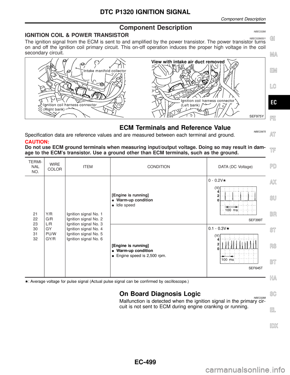
Component DescriptionNBEC0286IGNITION COIL & POWER TRANSISTORNBEC0286S01The ignition signal from the ECM is sent to and amplified by the power transistor. The power transistor turns
on and off the ignition coil primary circuit. This on-off operation induces the proper high voltage in the coil
secondary circuit.
SEF975Y
ECM Terminals and Reference ValueNBEC0675Specification data are reference values and are measured between each terminal and ground.
CAUTION:
Do not use ECM ground terminals when measuring input/output voltage. Doing so may result in dam-
age to the ECM's transistor. Use a ground other than ECM terminals, such as the ground.
TERMI-
NAL
NO.WIRE
COLORITEM CONDITION DATA (DC Voltage)
21
22
23
30
31
32Y/R
G/R
L/R
GY
PU/W
GY/RIgnition signal No. 1
Ignition signal No. 2
Ignition signal No. 3
Ignition signal No. 4
Ignition signal No. 5
Ignition signal No. 6[Engine is running]
IWarm-up condition
IIdle speed0 - 0.2VH
SEF399T
[Engine is running]
IWarm-up condition
IEngine speed is 2,500 rpm.0.1 - 0.3VH
SEF645T
H: Average voltage for pulse signal (Actual pulse signal can be confirmed by oscilloscope.)
On Board Diagnosis LogicNBEC0288Malfunction is detected when the ignition signal in the primary cir-
cuit is not sent to ECM during engine cranking or running.
GI
MA
EM
LC
FE
AT
TF
PD
AX
SU
BR
ST
RS
BT
HA
SC
EL
IDX
DTC P1320 IGNITION SIGNAL
Component Description
EC-499
Page 1088 of 2395

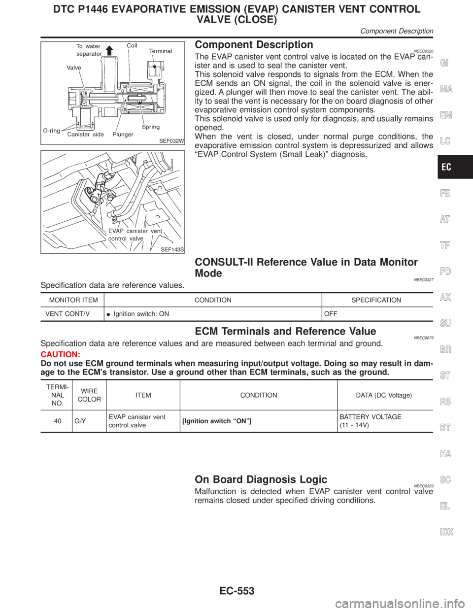
SEF032W
SEF143S
Component DescriptionNBEC0326The EVAP canister vent control valve is located on the EVAP can-
ister and is used to seal the canister vent.
This solenoid valve responds to signals from the ECM. When the
ECM sends an ON signal, the coil in the solenoid valve is ener-
gized. A plunger will then move to seal the canister vent. The abil-
ity to seal the vent is necessary for the on board diagnosis of other
evaporative emission control system components.
This solenoid valve is used only for diagnosis, and usually remains
opened.
When the vent is closed, under normal purge conditions, the
evaporative emission control system is depressurized and allows
ªEVAP Control System (Small Leak)º diagnosis.
CONSULT-II Reference Value in Data Monitor
Mode
NBEC0327Specification data are reference values.
MONITOR ITEM CONDITION SPECIFICATION
VENT CONT/VIIgnition switch: ON OFF
ECM Terminals and Reference ValueNBEC0679Specification data are reference values and are measured between each terminal and ground.
CAUTION:
Do not use ECM ground terminals when measuring input/output voltage. Doing so may result in dam-
age to the ECM's transistor. Use a ground other than ECM terminals, such as the ground.
TERMI-
NAL
NO.WIRE
COLORITEM CONDITION DATA (DC Voltage)
40 G/YEVAP canister vent
control valve[Ignition switch ªONº]BATTERY VOLTAGE
(11 - 14V)
On Board Diagnosis LogicNBEC0329Malfunction is detected when EVAP canister vent control valve
remains closed under specified driving conditions.
GI
MA
EM
LC
FE
AT
TF
PD
AX
SU
BR
ST
RS
BT
HA
SC
EL
IDX
DTC P1446 EVAPORATIVE EMISSION (EVAP) CANISTER VENT CONTROL
VALVE (CLOSE)
Component Description
EC-553
Page 1108 of 2395

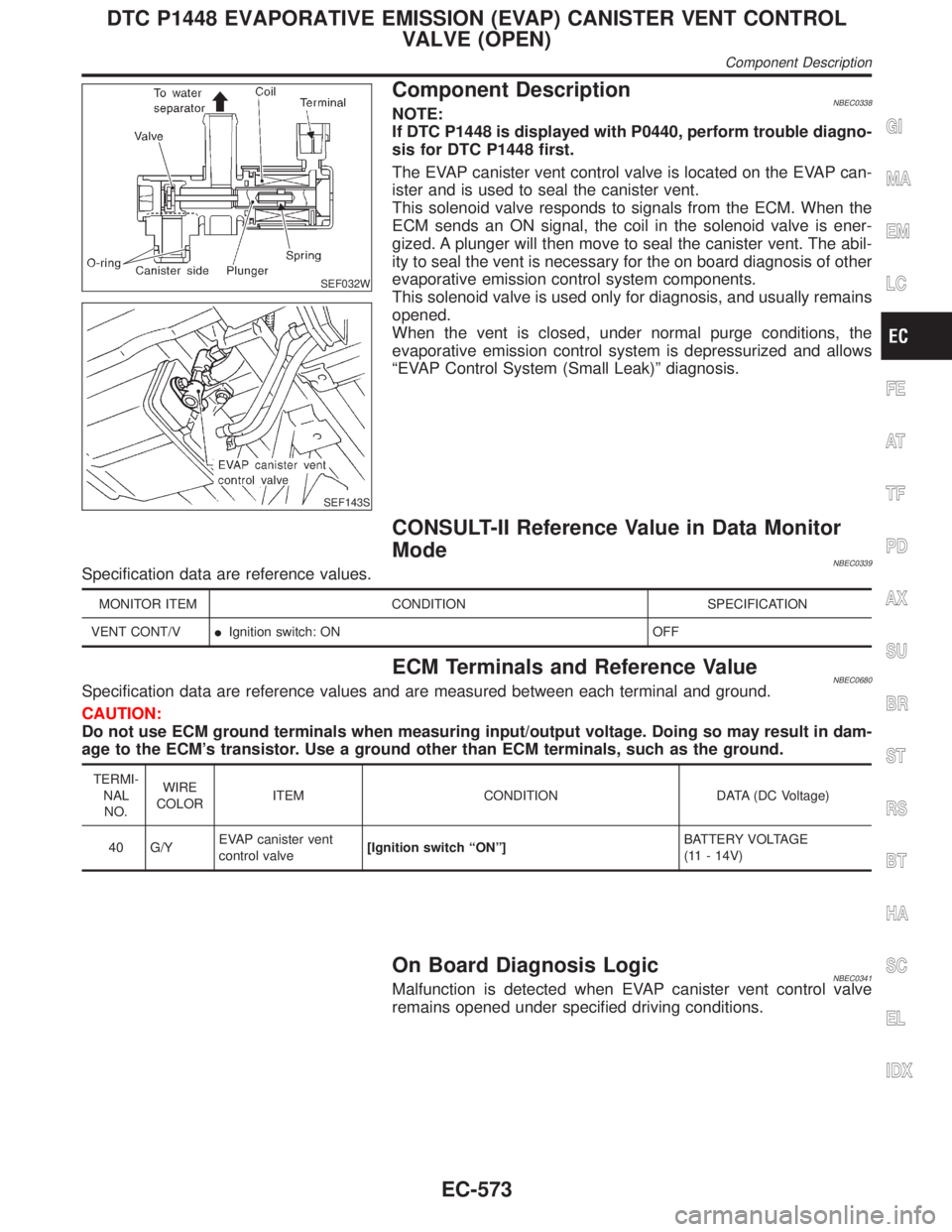
SEF032W
SEF143S
Component DescriptionNBEC0338NOTE:
If DTC P1448 is displayed with P0440, perform trouble diagno-
sis for DTC P1448 first.
The EVAP canister vent control valve is located on the EVAP can-
ister and is used to seal the canister vent.
This solenoid valve responds to signals from the ECM. When the
ECM sends an ON signal, the coil in the solenoid valve is ener-
gized. A plunger will then move to seal the canister vent. The abil-
ity to seal the vent is necessary for the on board diagnosis of other
evaporative emission control system components.
This solenoid valve is used only for diagnosis, and usually remains
opened.
When the vent is closed, under normal purge conditions, the
evaporative emission control system is depressurized and allows
ªEVAP Control System (Small Leak)º diagnosis.
CONSULT-II Reference Value in Data Monitor
Mode
NBEC0339Specification data are reference values.
MONITOR ITEM CONDITION SPECIFICATION
VENT CONT/VIIgnition switch: ON OFF
ECM Terminals and Reference ValueNBEC0680Specification data are reference values and are measured between each terminal and ground.
CAUTION:
Do not use ECM ground terminals when measuring input/output voltage. Doing so may result in dam-
age to the ECM's transistor. Use a ground other than ECM terminals, such as the ground.
TERMI-
NAL
NO.WIRE
COLORITEM CONDITION DATA (DC Voltage)
40 G/YEVAP canister vent
control valve[Ignition switch ªONº]BATTERY VOLTAGE
(11 - 14V)
On Board Diagnosis LogicNBEC0341Malfunction is detected when EVAP canister vent control valve
remains opened under specified driving conditions.
GI
MA
EM
LC
FE
AT
TF
PD
AX
SU
BR
ST
RS
BT
HA
SC
EL
IDX
DTC P1448 EVAPORATIVE EMISSION (EVAP) CANISTER VENT CONTROL
VALVE (OPEN)
Component Description
EC-573
Page 1120 of 2395

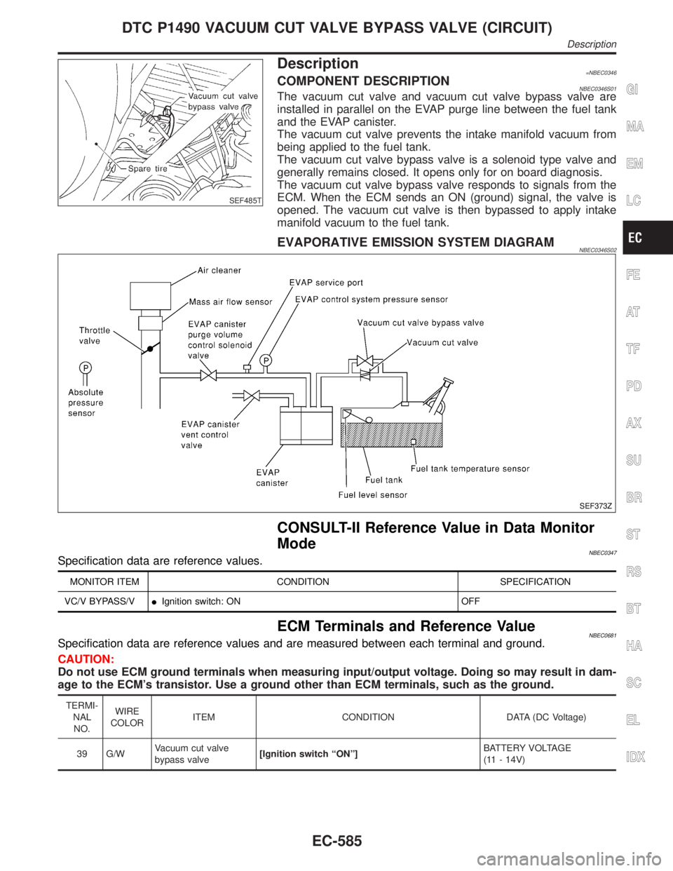
SEF485T
Description=NBEC0346COMPONENT DESCRIPTIONNBEC0346S01The vacuum cut valve and vacuum cut valve bypass valve are
installed in parallel on the EVAP purge line between the fuel tank
and the EVAP canister.
The vacuum cut valve prevents the intake manifold vacuum from
being applied to the fuel tank.
The vacuum cut valve bypass valve is a solenoid type valve and
generally remains closed. It opens only for on board diagnosis.
The vacuum cut valve bypass valve responds to signals from the
ECM. When the ECM sends an ON (ground) signal, the valve is
opened. The vacuum cut valve is then bypassed to apply intake
manifold vacuum to the fuel tank.
EVAPORATIVE EMISSION SYSTEM DIAGRAMNBEC0346S02
SEF373Z
CONSULT-II Reference Value in Data Monitor
Mode
NBEC0347Specification data are reference values.
MONITOR ITEM CONDITION SPECIFICATION
VC/V BYPASS/VIIgnition switch: ON OFF
ECM Terminals and Reference ValueNBEC0681Specification data are reference values and are measured between each terminal and ground.
CAUTION:
Do not use ECM ground terminals when measuring input/output voltage. Doing so may result in dam-
age to the ECM's transistor. Use a ground other than ECM terminals, such as the ground.
TERMI-
NAL
NO.WIRE
COLORITEM CONDITION DATA (DC Voltage)
39 G/WVacuum cut valve
bypass valve[Ignition switch ªONº]BATTERY VOLTAGE
(11 - 14V)
GI
MA
EM
LC
FE
AT
TF
PD
AX
SU
BR
ST
RS
BT
HA
SC
EL
IDX
DTC P1490 VACUUM CUT VALVE BYPASS VALVE (CIRCUIT)
Description
EC-585