2001 INFINITI QX4 charge
[x] Cancel search: chargePage 1916 of 2395
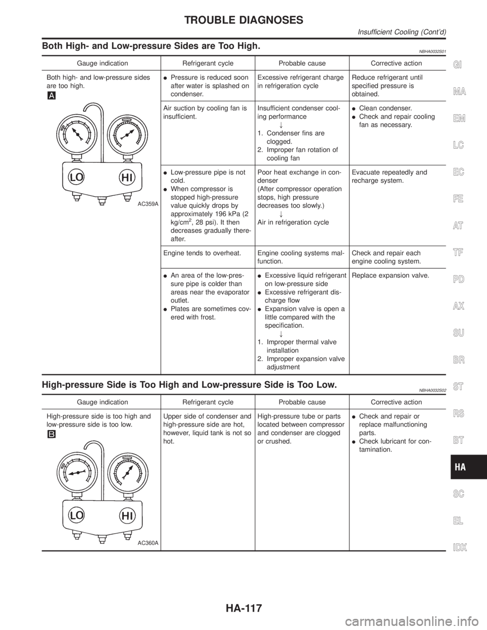
Both High- and Low-pressure Sides are Too High.NBHA0032S01
Gauge indication Refrigerant cycle Probable cause Corrective action
Both high- and low-pressure sides
are too high.
AC359A
IPressure is reduced soon
after water is splashed on
condenser.Excessive refrigerant charge
in refrigeration cycleReduce refrigerant until
specified pressure is
obtained.
Air suction by cooling fan is
insufficient.Insufficient condenser cool-
ing performance
"
1. Condenser fins are
clogged.
2. Improper fan rotation of
cooling fanIClean condenser.
ICheck and repair cooling
fan as necessary.
ILow-pressure pipe is not
cold.
IWhen compressor is
stopped high-pressure
value quickly drops by
approximately 196 kPa (2
kg/cm
2, 28 psi). It then
decreases gradually there-
after.Poor heat exchange in con-
denser
(After compressor operation
stops, high pressure
decreases too slowly.)
"
Air in refrigeration cycleEvacuate repeatedly and
recharge system.
Engine tends to overheat. Engine cooling systems mal-
function.Check and repair each
engine cooling system.
IAn area of the low-pres-
sure pipe is colder than
areas near the evaporator
outlet.
IPlates are sometimes cov-
ered with frost.IExcessive liquid refrigerant
on low-pressure side
IExcessive refrigerant dis-
charge flow
IExpansion valve is open a
little compared with the
specification.
"
1. Improper thermal valve
installation
2. Improper expansion valve
adjustmentReplace expansion valve.
High-pressure Side is Too High and Low-pressure Side is Too Low.NBHA0032S02
Gauge indication Refrigerant cycle Probable cause Corrective action
High-pressure side is too high and
low-pressure side is too low.
AC360A
Upper side of condenser and
high-pressure side are hot,
however, liquid tank is not so
hot.High-pressure tube or parts
located between compressor
and condenser are clogged
or crushed.ICheck and repair or
replace malfunctioning
parts.
ICheck lubricant for con-
tamination.
GI
MA
EM
LC
EC
FE
AT
TF
PD
AX
SU
BR
ST
RS
BT
SC
EL
IDX
TROUBLE DIAGNOSES
Insufficient Cooling (Cont'd)
HA-117
Page 1918 of 2395
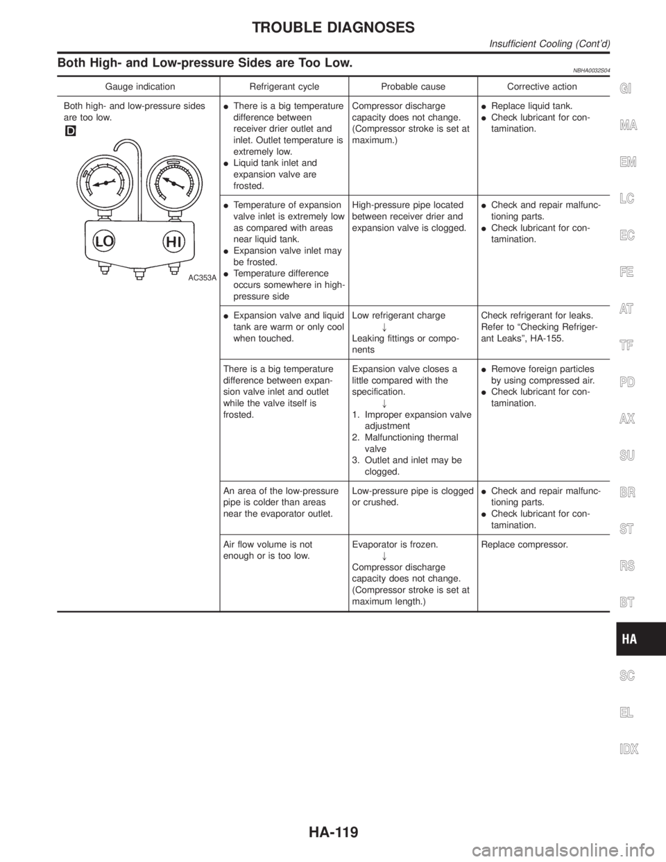
Both High- and Low-pressure Sides are Too Low.NBHA0032S04
Gauge indication Refrigerant cycle Probable cause Corrective action
Both high- and low-pressure sides
are too low.
AC353A
IThere is a big temperature
difference between
receiver drier outlet and
inlet. Outlet temperature is
extremely low.
ILiquid tank inlet and
expansion valve are
frosted.Compressor discharge
capacity does not change.
(Compressor stroke is set at
maximum.)IReplace liquid tank.
ICheck lubricant for con-
tamination.
ITemperature of expansion
valve inlet is extremely low
as compared with areas
near liquid tank.
IExpansion valve inlet may
be frosted.
ITemperature difference
occurs somewhere in high-
pressure sideHigh-pressure pipe located
between receiver drier and
expansion valve is clogged.ICheck and repair malfunc-
tioning parts.
ICheck lubricant for con-
tamination.
IExpansion valve and liquid
tank are warm or only cool
when touched.Low refrigerant charge
"
Leaking fittings or compo-
nentsCheck refrigerant for leaks.
Refer to ªChecking Refriger-
ant Leaksº, HA-155.
There is a big temperature
difference between expan-
sion valve inlet and outlet
while the valve itself is
frosted.Expansion valve closes a
little compared with the
specification.
"
1. Improper expansion valve
adjustment
2. Malfunctioning thermal
valve
3. Outlet and inlet may be
clogged.IRemove foreign particles
by using compressed air.
ICheck lubricant for con-
tamination.
An area of the low-pressure
pipe is colder than areas
near the evaporator outlet.Low-pressure pipe is clogged
or crushed.ICheck and repair malfunc-
tioning parts.
ICheck lubricant for con-
tamination.
Air flow volume is not
enough or is too low.Evaporator is frozen.
"
Compressor discharge
capacity does not change.
(Compressor stroke is set at
maximum length.)Replace compressor.
GI
MA
EM
LC
EC
FE
AT
TF
PD
AX
SU
BR
ST
RS
BT
SC
EL
IDX
TROUBLE DIAGNOSES
Insufficient Cooling (Cont'd)
HA-119
Page 1919 of 2395
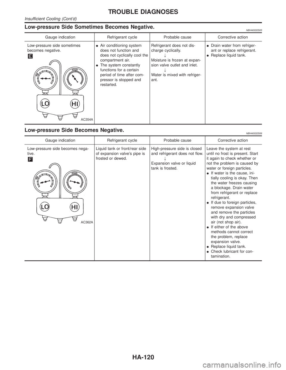
Low-pressure Side Sometimes Becomes Negative.NBHA0032S05
Gauge indication Refrigerant cycle Probable cause Corrective action
Low-pressure side sometimes
becomes negative.
AC354A
IAir conditioning system
does not function and
does not cyclically cool the
compartment air.
IThe system constantly
functions for a certain
period of time after com-
pressor is stopped and
restarted.Refrigerant does not dis-
charge cyclically.
"
Moisture is frozen at expan-
sion valve outlet and inlet.
"
Water is mixed with refriger-
ant.IDrain water from refriger-
ant or replace refrigerant.
IReplace liquid tank.
Low-pressure Side Becomes Negative.NBHA0032S06
Gauge indication Refrigerant cycle Probable cause Corrective action
Low-pressure side becomes nega-
tive.
AC362A
Liquid tank or front/rear side
of expansion valve's pipe is
frosted or dewed.High-pressure side is closed
and refrigerant does not flow.
"
Expansion valve or liquid
tank is frosted.Leave the system at rest
until no frost is present. Start
it again to check whether or
not the problem is caused by
water or foreign particles.
IIf water is the cause, ini-
tially cooling is okay. Then
the water freezes causing
a blockage. Drain water
from refrigerant or replace
refrigerant.
IIf due to foreign particles,
remove expansion valve
and remove the particles
with dry and compressed
air (not shop air).
IIf either of the above
methods cannot correct
the problem, replace
expansion valve.
IReplace liquid tank.
ICheck lubricant for con-
tamination.
TROUBLE DIAGNOSES
Insufficient Cooling (Cont'd)
HA-120
Page 1931 of 2395
Temperature ÉC (ÉF) Resistance kW
35 (95) 1.51
40 (104) 1.27
45 (113) 1.07
If NG, replace ambient sensor.
RHA103G
In-vehicle Sensor Circuit
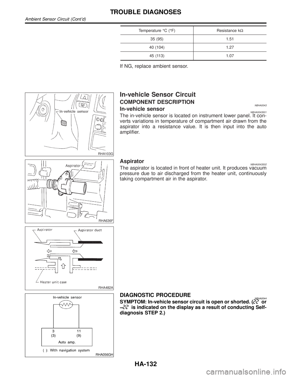
COMPONENT DESCRIPTIONNBHA0043In-vehicle sensorNBHA0043S01The in-vehicle sensor is located on instrument lower panel. It con-
verts variations in temperature of compartment air drawn from the
aspirator into a resistance value. It is then input into the auto
amplifier.
RHA636F
RHA482A
AspiratorNBHA0043S02The aspirator is located in front of heater unit. It produces vacuum
pressure due to air discharged from the heater unit, continuously
taking compartment air in the aspirator.
RHA056GH
DIAGNOSTIC PROCEDURENBHA0044SYMPTOM: In-vehicle sensor circuit is open or shorted. (or
þ
is indicated on the display as a result of conducting Self-
diagnosis STEP 2.)
TROUBLE DIAGNOSES
Ambient Sensor Circuit (Cont'd)
HA-132
Page 1943 of 2395
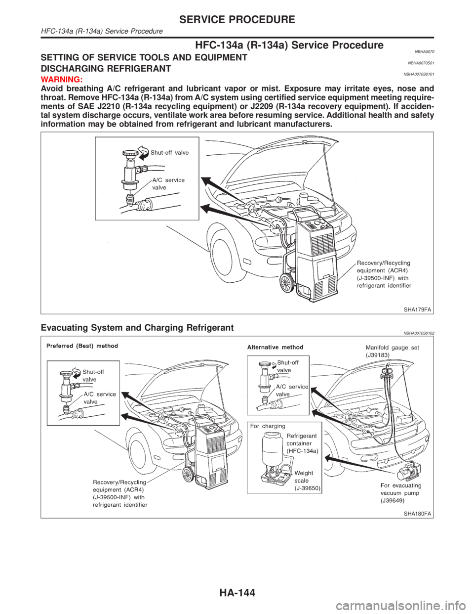
HFC-134a (R-134a) Service ProcedureNBHA0070SETTING OF SERVICE TOOLS AND EQUIPMENTNBHA0070S01DISCHARGING REFRIGERANTNBHA0070S0101WARNING:
Avoid breathing A/C refrigerant and lubricant vapor or mist. Exposure may irritate eyes, nose and
throat. Remove HFC-134a (R-134a) from A/C system using certified service equipment meeting require-
ments of SAE J2210 (R-134a recycling equipment) or J2209 (R-134a recovery equipment). If acciden-
tal system discharge occurs, ventilate work area before resuming service. Additional health and safety
information may be obtained from refrigerant and lubricant manufacturers.
SHA179FA
Evacuating System and Charging RefrigerantNBHA0070S0102
SHA180FA
SERVICE PROCEDURE
HFC-134a (R-134a) Service Procedure
HA-144
Page 1947 of 2395
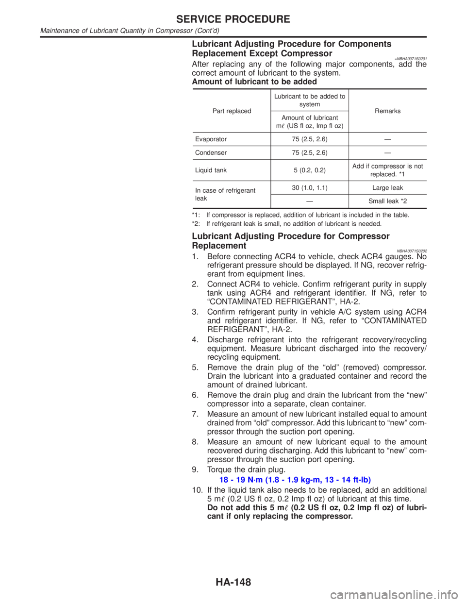
Lubricant Adjusting Procedure for Components
Replacement Except Compressor
=NBHA0071S0201After replacing any of the following major components, add the
correct amount of lubricant to the system.
Amount of lubricant to be added
Part replacedLubricant to be added to
system
Remarks
Amount of lubricant
m(US fl oz, Imp fl oz)
Evaporator 75 (2.5, 2.6) Ð
Condenser 75 (2.5, 2.6) Ð
Liquid tank 5 (0.2, 0.2)Add if compressor is not
replaced. *1
In case of refrigerant
leak30 (1.0, 1.1) Large leak
Ð Small leak *2
*1: If compressor is replaced, addition of lubricant is included in the table.
*2: If refrigerant leak is small, no addition of lubricant is needed.
Lubricant Adjusting Procedure for Compressor
Replacement
NBHA0071S02021. Before connecting ACR4 to vehicle, check ACR4 gauges. No
refrigerant pressure should be displayed. If NG, recover refrig-
erant from equipment lines.
2. Connect ACR4 to vehicle. Confirm refrigerant purity in supply
tank using ACR4 and refrigerant identifier. If NG, refer to
ªCONTAMINATED REFRIGERANTº, HA-2.
3. Confirm refrigerant purity in vehicle A/C system using ACR4
and refrigerant identifier. If NG, refer to ªCONTAMINATED
REFRIGERANTº, HA-2.
4. Discharge refrigerant into the refrigerant recovery/recycling
equipment. Measure lubricant discharged into the recovery/
recycling equipment.
5. Remove the drain plug of the ªoldº (removed) compressor.
Drain the lubricant into a graduated container and record the
amount of drained lubricant.
6. Remove the drain plug and drain the lubricant from the ªnewº
compressor into a separate, clean container.
7. Measure an amount of new lubricant installed equal to amount
drained from ªoldº compressor. Add this lubricant to ªnewº com-
pressor through the suction port opening.
8. Measure an amount of new lubricant equal to the amount
recovered during discharging. Add this lubricant to ªnewº com-
pressor through the suction port opening.
9. Torque the drain plug.
18 - 19 N´m (1.8 - 1.9 kg-m, 13 - 14 ft-lb)
10. If the liquid tank also needs to be replaced, add an additional
5m(0.2 US fl oz, 0.2 Imp fl oz) of lubricant at this time.
Do not add this 5 m(0.2 US fl oz, 0.2 Imp fl oz) of lubri-
cant if only replacing the compressor.
SERVICE PROCEDURE
Maintenance of Lubricant Quantity in Compressor (Cont'd)
HA-148
Page 1956 of 2395
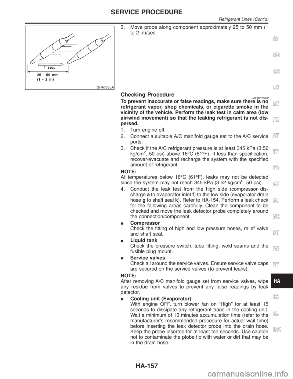
SHA708EA
3. Move probe along component approximately 25 to 50 mm (1
to 2 in)/sec.
Checking ProcedureNBHA0115S02To prevent inaccurate or false readings, make sure there is no
refrigerant vapor, shop chemicals, or cigarette smoke in the
vicinity of the vehicle. Perform the leak test in calm area (low
air/wind movement) so that the leaking refrigerant is not dis-
persed.
1. Turn engine off.
2. Connect a suitable A/C manifold gauge set to the A/C service
ports.
3. Check if the A/C refrigerant pressure is at least 345 kPa (3.52
kg/cm
2, 50 psi) above 16ÉC (61ÉF). If less than specification,
recover/evacuate and recharge the system with the specified
amount of refrigerant.
NOTE:
At temperatures below 16ÉC (61ÉF), leaks may not be detected
since the system may not reach 345 kPa (3.52 kg/cm
2, 50 psi).
4. Conduct the leak test from the high side (compressor dis-
chargeato evaporator inletf) to the low side (evaporator drain
hosegto shaft sealk). Refer to HA-154. Perform a leak check
for the following areas carefully. Clean the component to be
checked and move the leak detector probe completely around
the connection/component.
ICompressor
Check the fitting of high and low pressure hoses, relief valve
and shaft seal.
ILiquid tank
Check the pressure switch, tube fitting, weld seams and the
fusible plug mount.
IService valves
Check all around the service valves. Ensure service valve caps
are secured on the service valves (to prevent leaks).
NOTE:
After removing A/C manifold gauge set from service valves, wipe
any residue from valves to prevent any false readings by leak
detector.
ICooling unit (Evaporator)
With engine OFF, turn blower fan on ªHighº for at least 15
seconds to dissipate any refrigerant trace in the cooling unit.
Wait a minimum of 10 minutes accumulation time (refer to the
manufacturer's recommended procedure for actual wait time)
before inserting the leak detector probe into the drain hose.
Keep the probe inserted for at least ten seconds. Use caution
not to contaminate the ptobe tip with water or dirt that may be
in the drain hose.
GI
MA
EM
LC
EC
FE
AT
TF
PD
AX
SU
BR
ST
RS
BT
SC
EL
IDX
SERVICE PROCEDURE
Refrigerant Lines (Cont'd)
HA-157
Page 1957 of 2395
5. If a leak detector detects a leak, verify at least once by blow-
ing compressed air into area of suspected leak, then repeat
check as outlined above.
6. Do not stop when one leak is found. Continue to check for
additional leaks at all system components.
If no leaks are found, perform steps7-10.
7. Start engine.
8. Set the heater A/C control as follows:
1) A/C switch ON.
2) Face mode
3) Recirculation switch ON
4) Max cold temperature
5) Fan speed high
9. Run engine at 1,500 rpm for at least 2 minutes.
10. Turn engine off and perform leak check again following steps
4 through 6 above.
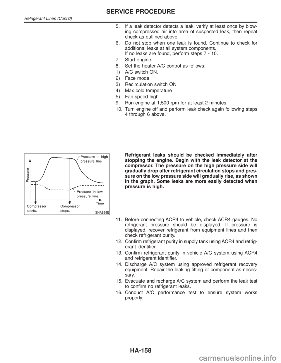
SHA839E
Refrigerant leaks should be checked immediately after
stopping the engine. Begin with the leak detector at the
compressor. The pressure on the high pressure side will
gradually drop after refrigerant circulation stops and pres-
sure on the low pressure side will gradually rise, as shown
in the graph. Some leaks are more easily detected when
pressure is high.
11. Before connecting ACR4 to vehicle, check ACR4 gauges. No
refrigerant pressure should be displayed. If pressure is
displayed, recover refrigerant from equipment lines and then
check refrigerant purity.
12. Confirm refrigerant purity in supply tank using ACR4 and refrig-
erant identifier.
13. Confirm refrigerant purity in vehicle A/C system using ACR4
and refrigerant identifier.
14. Discharge A/C system using approved refrigerant recovery
equipment. Repair the leaking fitting or component as neces-
sary.
15. Evacuate and recharge A/C system and perform the leak test
to confirm no refrigerant leaks.
16. Conduct A/C performance test to ensure system works
properly.
SERVICE PROCEDURE
Refrigerant Lines (Cont'd)
HA-158