Page 1807 of 2395

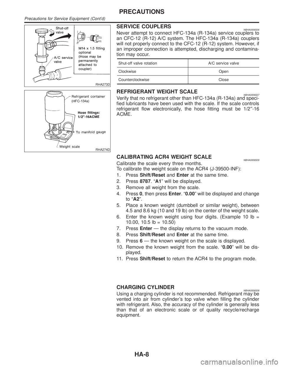
RHA273D
SERVICE COUPLERSNBHA0006S06Never attempt to connect HFC-134a (R-134a) service couplers to
an CFC-12 (R-12) A/C system. The HFC-134a (R-134a) couplers
will not properly connect to the CFC-12 (R-12) system. However, if
an improper connection is attempted, discharging and contamina-
tion may occur.
Shut-off valve rotation A/C service valve
Clockwise Open
Counterclockwise Close
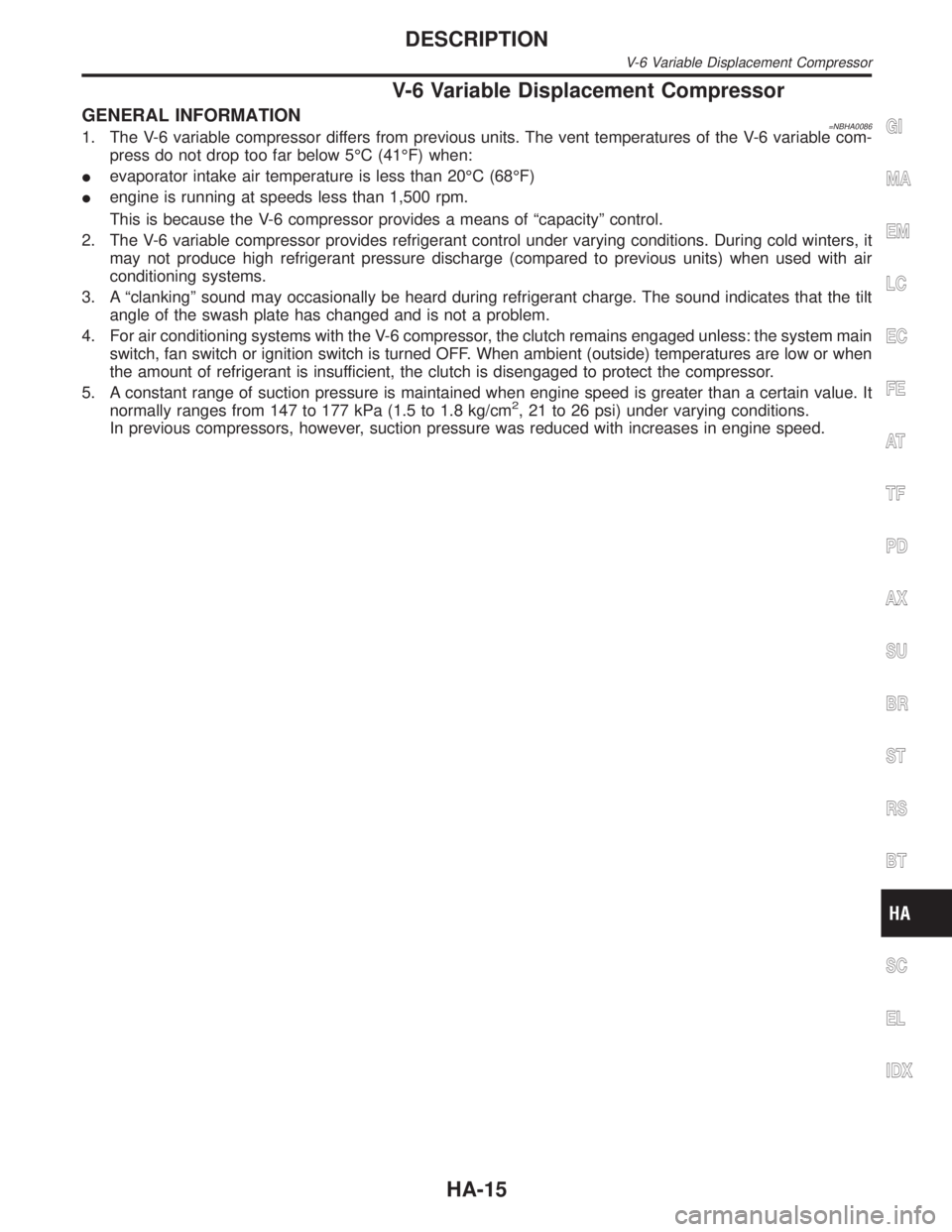
RHA274D
REFRIGERANT WEIGHT SCALENBHA0006S07Verify that no refrigerant other than HFC-134a (R-134a) and speci-
fied lubricants have been used with the scale. If the scale controls
refrigerant flow electronically, the hose fitting must be 1/2²-16
ACME.
CALIBRATING ACR4 WEIGHT SCALENBHA0006S09Calibrate the scale every three months.
To calibrate the weight scale on the ACR4 (J-39500-INF):
1. PressShift/ResetandEnterat the same time.
2. Press8787.ªA1º will be displayed.
3. Remove all weight from the scale.
4. Press0, then pressEnter.ª0.00º will be displayed and change
to ªA2º.
5. Place a known weight (dumbbell or similar weight), between
4.5 and 8.6 kg (10 and 19 lb) on the center of the weight scale.
6. Enter the known weight using four digits. (Example 10 lb =
10.00, 10.5 lb = 10.50)
7. PressEnterÐ the display returns to the vacuum mode.
8. PressShift/ResetandEnterat the same time.
9. Press6Ð the known weight on the scale is displayed.
10. Remove the known weight from the scale. ª0.00º will be dis-
played.
11. PressShift/Resetto return the ACR4 to the program mode.
CHARGING CYLINDERNBHA0006S08Using a charging cylinder is not recommended. Refrigerant may be
vented into air from cylinder's top valve when filling the cylinder
with refrigerant. Also, the accuracy of the cylinder is generally less
than that of an electronic scale or of quality recycle/recharge
equipment.
PRECAUTIONS
Precautions for Service Equipment (Cont'd)
HA-8
Page 1814 of 2395

V-6 Variable Displacement Compressor
GENERAL INFORMATION=NBHA00861. The V-6 variable compressor differs from previous units. The vent temperatures of the V-6 variable com-
press do not drop too far below 5ÉC (41ÉF) when:
Ievaporator intake air temperature is less than 20ÉC (68ÉF)
Iengine is running at speeds less than 1,500 rpm.
This is because the V-6 compressor provides a means of ªcapacityº control.
2. The V-6 variable compressor provides refrigerant control under varying conditions. During cold winters, it
may not produce high refrigerant pressure discharge (compared to previous units) when used with air
conditioning systems.
3. A ªclankingº sound may occasionally be heard during refrigerant charge. The sound indicates that the tilt
angle of the swash plate has changed and is not a problem.
4. For air conditioning systems with the V-6 compressor, the clutch remains engaged unless: the system main
switch, fan switch or ignition switch is turned OFF. When ambient (outside) temperatures are low or when
the amount of refrigerant is insufficient, the clutch is disengaged to protect the compressor.
5. A constant range of suction pressure is maintained when engine speed is greater than a certain value. It
normally ranges from 147 to 177 kPa (1.5 to 1.8 kg/cm
2, 21 to 26 psi) under varying conditions.
In previous compressors, however, suction pressure was reduced with increases in engine speed.
GI
MA
EM
LC
EC
FE
AT
TF
PD
AX
SU
BR
ST
RS
BT
SC
EL
IDX
DESCRIPTION
V-6 Variable Displacement Compressor
HA-15
Page 1815 of 2395
DESCRIPTION=NBHA0087GeneralNBHA0087S01The variable compressor is basically a swash plate type that changes piston stroke in response to the required
cooling capacity.
The tilt of the swash plate allows the piston's stroke to change so that refrigerant discharge can be continu-
ously changed from 14.5 to 184 cm
3(0.885 to 11.228 cu in).
RHA037DD
DESCRIPTION
V-6 Variable Displacement Compressor (Cont'd)
HA-16
Page 1817 of 2395

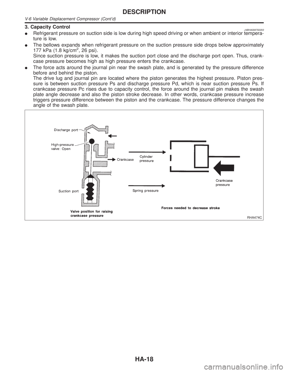
3. Capacity Control=NBHA0087S0203IRefrigerant pressure on suction side is low during high speed driving or when ambient or interior tempera-
ture is low.
IThe bellows expands when refrigerant pressure on the suction pressure side drops below approximately
177 kPa (1.8 kg/cm
2, 26 psi).
Since suction pressure is low, it makes the suction port close and the discharge port open. Thus, crank-
case pressure becomes high as high pressure enters the crankcase.
IThe force acts around the journal pin near the swash plate, and is generated by the pressure difference
before and behind the piston.
The drive lug and journal pin are located where the piston generates the highest pressure. Piston pres-
sure is between suction pressure Ps and discharge pressure Pd, which is near suction pressure Ps. If
crankcase pressure Pc rises due to capacity control, the force around the journal pin makes the swash
plate angle decrease and also the piston stroke decrease. In other words, crankcase pressure increase
triggers pressure difference between the piston and the crankcase. The pressure difference changes the
angle of the swash plate.
RHA474C
DESCRIPTION
V-6 Variable Displacement Compressor (Cont'd)
HA-18
Page 1823 of 2395

RHA328HA
DISPLAY SCREENNBHA0016S01Displays the operational status of the system.
AUTO SWITCHNBHA0016S02The compressor, intake doors, air mix door, outlet doors, and blower speed are automatically controlled so
that the in-vehicle temperature will reach, and be maintained at the set temperature selected by the operator.
ECON SWITCHNBHA0016S03By pressing the ECON switch, the display should indicate ECON and the compressor always turns OFF. With
the compressor OFF, the system will not remove heat (cool) or de-humidify. The system will maintain the in-
vehicle temperature at the set temperature when the set temperature is above the ambient (outside) tempera-
ture. The system will set the intake doors to the outside air position.
TEMPERATURE SWITCH (POTENTIO TEMPERATURE CONTROL) WITHOUT NAVIGATION
SYSTEM
NBHA0016S04Increases or decreases the set temperature.
OFF SWITCHNBHA0016S05The compressor and blower are OFF, the intake doors are set to the outside air position, and the air outlet
doors are set to the foot (80% foot and 20% defrost) position.
FAN SWITCHNBHA0016S06Manually controls the blower speed. Four speeds are available for manual control (as shown on the display
screen):
low
, medium low, medium high, high
RECIRCULATION (REC) SWITCHNBHA0016S07OFF position: Outside air is drawn into the passenger compartment.
ON position: Interior air is recirculated inside the vehicle.
DEFROSTER (DEF) SWITCHNBHA0016S08Positions the air outlet doors to the defrost position. Also positions the intake doors to the outside air position.
MODE SWITCHNBHA0016S09Controls the air discharge outlets.
TEMPERATURE DIAL (POTENTIO TEMPERATURE CONTROL) WITH NAVIGATION SYSTEMNBHA0016S10Increases or decreases the set temperature.
AMB (AMBIENT) SWITCH (WITH NAVIGATION SYSTEM)NBHA0016S11Shows the ambient (outside) air temperature on the display screen for 5 seconds.
DESCRIPTION
Control Operation (Cont'd)
HA-24
Page 1824 of 2395
Discharge Air FlowNBHA0017
RHA043G
GI
MA
EM
LC
EC
FE
AT
TF
PD
AX
SU
BR
ST
RS
BT
SC
EL
IDX
DESCRIPTION
Discharge Air Flow
HA-25
Page 1847 of 2395
8 CHECK ACTUATORS
Refer to the following chart and confirm discharge air flow, air temperature, blower motor voltage and compressor opera-
tion.
Checks must be made visually, by listening to any noise, or by touching air outlets with your hand, etc. for
improper operation.
MTBL0200
MTBL0044
OK or NG
OK©GO TO 9.
NG©IAir outlet does not change.
Go to ªMode Door Motorº (HA-75).
IIntake door does not change.
Go to ªIntake Door Motorº (HA-87).
IBlower motor operation is malfunctioning.
Go to ªBlower Motorº (HA-95).
IMagnet clutch does not engage.
Go to ªMagnet Clutchº (HA-104).
IDischarge air temperature does not change.
Go to ªAir Mix Door Motorº (HA-82).
TROUBLE DIAGNOSES
Self-diagnosis (Cont'd)
HA-48
Page 1857 of 2395
8 CHECK ACTUATORS
Refer to the following chart and confirm discharge air flow, air temperature, blower motor voltage and compressor opera-
tion.
Checks must be made visually, by listening to any noise, or by touching air outlets with your hand, etc. for
improper operation.
MTBL0200
MTBL0044
OK or NG
OK©GO TO 9.
NG©IAir outlet does not change.
Go to ªMode Door Motorº (HA-75).
IIntake door does not change.
Go to ªIntake Door Motorº (HA-87).
IBlower motor operation is malfunctioning.
Go to ªBlower Motorº (HA-95).
IMagnet clutch does not engage.
Go to ªMagnet Clutchº (HA-104).
IDischarge air temperature does not change.
Go to ªAir Mix Door Motorº (HA-82).
TROUBLE DIAGNOSES
Self-diagnosis (Cont'd)
HA-58