Page 1145 of 2395

DescriptionNBEC0596SYSTEM DESCRIPTIONNBEC0596S01
Sensor Input Signal to ECMECM func-
tionActuator
Mass air flow sensor Amount of intake air
VIAS con-
trolVIAS control solenoid valve Throttle position sensor Throttle position
Closed throttle position Throttle valve idle position
Ignition switch Start signal
Crankshaft position sensor (POS) Engine speed (POS signal)
Crankshaft position sensor (REF) Engine speed (REF signal)
Engine coolant temperature sensor Engine coolant temperature
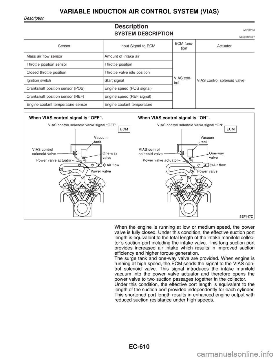
SEF447Z
When the engine is running at low or medium speed, the power
valve is fully closed. Under this condition, the effective suction port
length is equivalent to the total length of the intake manifold collec-
tor's suction port including the intake valve. This long suction port
provides increased air intake which results in improved suction
efficiency and higher torque generation.
The surge tank and one-way valve are provided. When engine is
running at high speed, the ECM sends the signal to the VIAS con-
trol solenoid valve. This signal introduces the intake manifold
vacuum into the power valve actuator and therefore opens the
power valve to two suction passages together in the collector.
Under this condition, the effective port length is equivalent to the
length of the suction port provided independently for each cylinder.
This shortened port length results in enhanced engine output with
reduced suction resistance under high speeds.
VARIABLE INDUCTION AIR CONTROL SYSTEM (VIAS)
Description
EC-610
Page 1149 of 2395

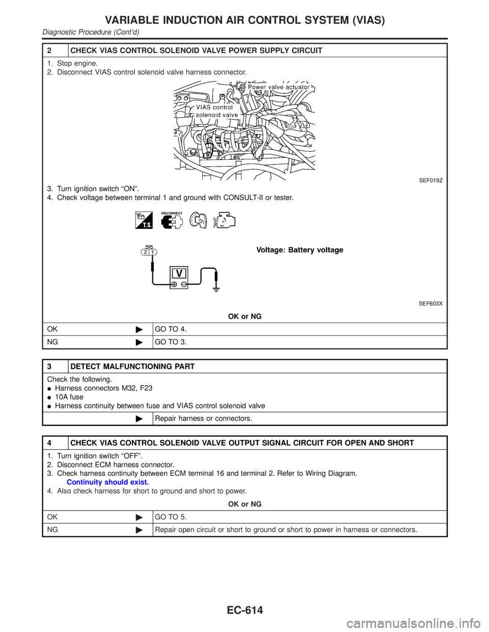
2 CHECK VIAS CONTROL SOLENOID VALVE POWER SUPPLY CIRCUIT
1. Stop engine.
2. Disconnect VIAS control solenoid valve harness connector.
SEF019Z
3. Turn ignition switch ªONº.
4. Check voltage between terminal 1 and ground with CONSULT-II or tester.
SEF603X
OK or NG
OK©GO TO 4.
NG©GO TO 3.
3 DETECT MALFUNCTIONING PART
Check the following.
IHarness connectors M32, F23
I10A fuse
IHarness continuity between fuse and VIAS control solenoid valve
©Repair harness or connectors.
4 CHECK VIAS CONTROL SOLENOID VALVE OUTPUT SIGNAL CIRCUIT FOR OPEN AND SHORT
1. Turn ignition switch ªOFFº.
2. Disconnect ECM harness connector.
3. Check harness continuity between ECM terminal 16 and terminal 2. Refer to Wiring Diagram.
Continuity should exist.
4. Also check harness for short to ground and short to power.
OK or NG
OK©GO TO 5.
NG©Repair open circuit or short to ground or short to power in harness or connectors.
VARIABLE INDUCTION AIR CONTROL SYSTEM (VIAS)
Diagnostic Procedure (Cont'd)
EC-614
Page 1153 of 2395
Diagnostic ProcedureNBEC0387
1 INSPECTION START
Turn ignition switch to ªSTARTº.
Is any cylinder ignited?
YesorNo
Ye s©GO TO 2.
No©GO TO 3.
2 CHECK OVERALL FUNCTION
With CONSULT-II
1. Start engine.
2. Perform ªPOWER BALANCEº in ªACTIVE TESTº mode with CONSULT-II.
SEF190Y
3. Make sure that each circuit produces a momentary engine speed drop.
Without CONSULT-II
1. Start engine.
2. Listen to each injector operating sound.
MEC703B
Clicking noise should be heard.
OK or NG
OK©INSPECTION END
NG©GO TO 3.
INJECTOR
Diagnostic Procedure
EC-618
Page 1154 of 2395
3 CHECK INJECTOR POWER SUPPLY CIRCUIT
1. Turn ignition switch ªOFFº.
SEF023Z
2. Turn ignition switch ªONº.
3. Check voltage between injector terminal 1 and ground with CONSULT-II or tester.
SEF364Z
OK or NG
OK©GO TO 5.
NG©GO TO 4.
4 DETECT MALFUNCTIONING PART
Check the following.
IHarness connectors M33, F22
IHarness connectors F5, F100
IFuse block (J/B) connector M10
I10A fuse
IHarness for open or short between injector and fuse
©Repair harness or connectors.
5 CHECK INJECTOR OUTPUT SIGNAL CIRCUIT FOR OPEN AND SHORT
1. Turn ignition switch ªOFFº.
2. Disconnect ECM harness connector.
3. Check harness continuity between injector terminal 2 and ECM terminals 103, 104, 107, 101, 105, 102. Refer to Wiring
Diagram.
Continuity should exist.
4. Also check harness for short to ground and short to power.
OK or NG
OK©GO TO 7.
NG©GO TO 6.
GI
MA
EM
LC
FE
AT
TF
PD
AX
SU
BR
ST
RS
BT
HA
SC
EL
IDX
INJECTOR
Diagnostic Procedure (Cont'd)
EC-619
Page 1156 of 2395
CONSULT-II Reference Value in Data Monitor
Mode
NBEC0388Specification data are reference values.
MONITOR ITEM CONDITION SPECIFICATION
START SIGNALIIgnition switch: ON,START,ON OFF,ON,OFF
ECM Terminals and Reference ValueNBEC0688Specification data are reference values and are measured between each terminal and ground.
CAUTION:
Do not use ECM ground terminals when measuring input/output voltage. Doing so may result in dam-
age to the ECM's transistor. Use a ground other than ECM terminals, such as the ground.
TERMI-
NAL
NO.WIRE
COLORITEM CONDITION DATA (DC Voltage)
42 B/Y Start signal[Ignition switch ªONº]Approximately 0V
[Ignition switch ªSTARTº]9 - 12V
GI
MA
EM
LC
FE
AT
TF
PD
AX
SU
BR
ST
RS
BT
HA
SC
EL
IDX
START SIGNAL
CONSULT-II Reference Value in Data Monitor Mode
EC-621
Page 1158 of 2395
Diagnostic ProcedureNBEC0391
1 INSPECTION START
Do you have CONSULT-II?
YesorNo
Ye s©GO TO 2.
No©GO TO 3.
2 CHECK OVERALL FUNCTION
With CONSULT-II
1. Turn ignition switch ªONº.
2. Check ªSTART SIGNALº in ªDATA MONITORº mode with CONSULT-II under the following conditions.
SEF072Y
OK or NG
OK©INSPECTION END
NG©GO TO 4.
3 CHECK OVERALL FUNCTION
Without CONSULT-II
Check voltage between ECM terminal 42 and ground under the following conditions.
SEF362X
OK or NG
OK©INSPECTION END
NG©GO TO 4.
4 CHECK STARTING SYSTEM
Turn ignition switch ªOFFº, then turn it to ªSTARTº.
Does starter motor operate?
YesorNo
Ye s©GO TO 5.
No©Refer to SC-10, ªSTARTING SYSTEMº.
GI
MA
EM
LC
FE
AT
TF
PD
AX
SU
BR
ST
RS
BT
HA
SC
EL
IDX
START SIGNAL
Diagnostic Procedure
EC-623
Page 1159 of 2395

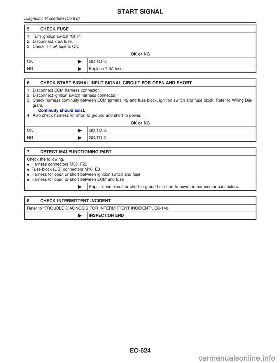
5 CHECK FUSE
1. Turn ignition switch ªOFFº.
2. Disconnect 7.5A fuse.
3. Check if 7.5A fuse is OK.
OK or NG
OK©GO TO 6.
NG©Replace 7.5A fuse.
6 CHECK START SIGNAL INPUT SIGNAL CIRCUIT FOR OPEN AND SHORT
1. Disconnect ECM harness connector.
2. Disconnect ignition switch harness connector.
3. Check harness continuity between ECM terminal 42 and fuse block, ignition switch and fuse block. Refer to Wiring Dia-
gram.
Continuity should exist.
4. Also check harness for short to ground and short to power.
OK or NG
OK©GO TO 8.
NG©GO TO 7.
7 DETECT MALFUNCTIONING PART
Check the following.
IHarness connectors M32, F23
IFuse block (J/B) connectors M10, E3
IHarness for open or short between ignition switch and fuse
IHarness for open or short between ECM and fuse
©Repair open circuit or short to ground or short to power in harness or connectors.
8 CHECK INTERMITTENT INCIDENT
Refer to ªTROUBLE DIAGNOSIS FOR INTERMITTENT INCIDENTº, EC-140.
©INSPECTION END
START SIGNAL
Diagnostic Procedure (Cont'd)
EC-624
Page 1160 of 2395

System DescriptionNBEC0392
Sensor Input Signal to ECMECM func-
tionActuator
Crankshaft position sensor (POS) Engine speed (POS signal)
Fuel pump
controlFuel pump relay Crankshaft position sensor (REF) Engine speed (REF signal)
Ignition switch Start signal
The ECM activates the fuel pump for several seconds after the ignition switch is turned on to improve engine
startability. If the ECM receives a 120É signal from the crankshaft position sensor (REF), it knows that the
engine is rotating, and causes the pump to operate. If the 120É signal is not received when the ignition switch
is on, the engine stalls. The ECM stops pump operation and prevents battery discharging, thereby improving
safety. The ECM does not directly drive the fuel pump. It controls the ON/OFF fuel pump relay, which in turn
controls the fuel pump.
Condition Fuel pump operation
Ignition switch is turned to ON. Operates for 1 second.
Engine running and cranking Operates.
When engine is stopped Stops in 1.5 seconds.
Except as shown aboveStops.
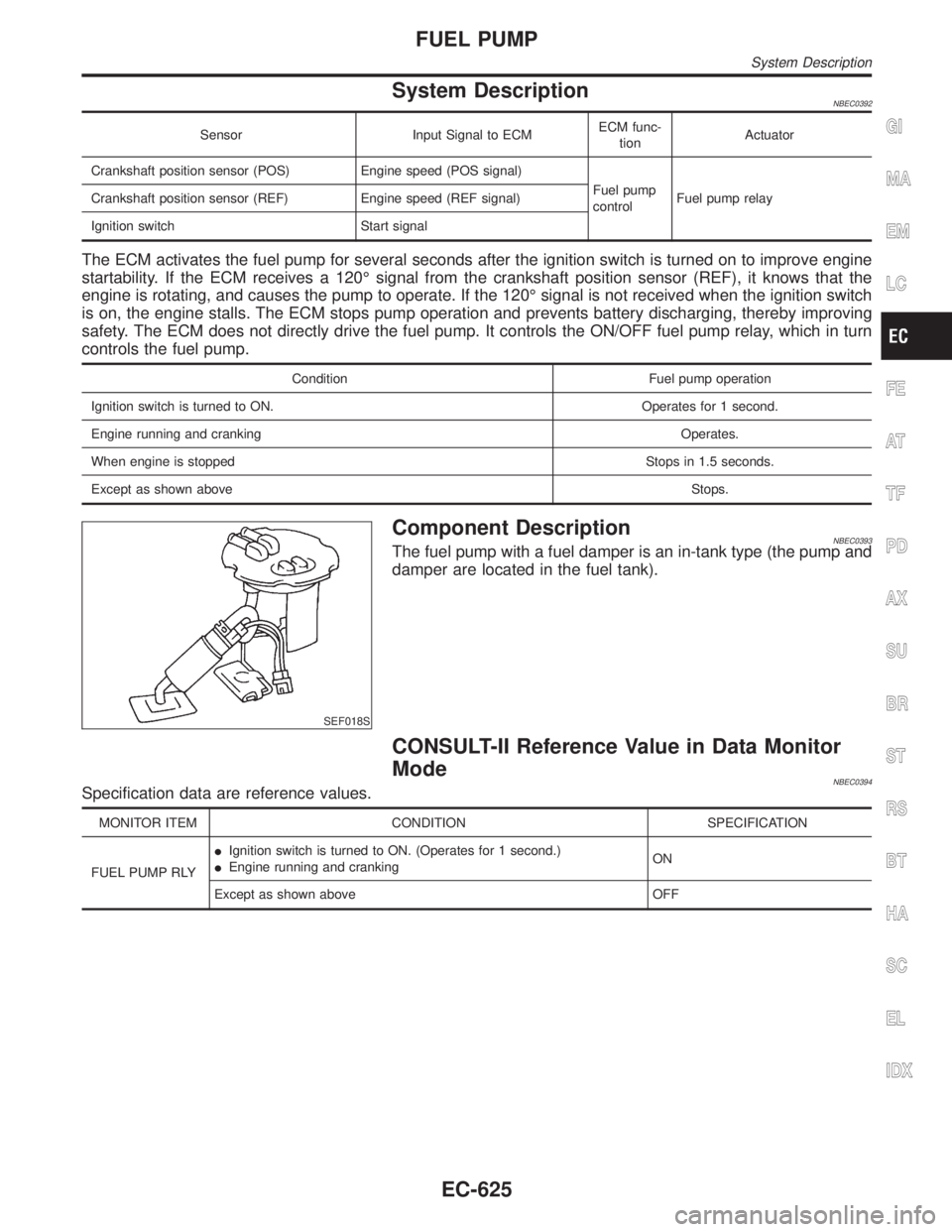
SEF018S
Component DescriptionNBEC0393The fuel pump with a fuel damper is an in-tank type (the pump and
damper are located in the fuel tank).
CONSULT-II Reference Value in Data Monitor
Mode
NBEC0394Specification data are reference values.
MONITOR ITEM CONDITION SPECIFICATION
FUEL PUMP RLYIIgnition switch is turned to ON. (Operates for 1 second.)
IEngine running and crankingON
Except as shown above OFF
GI
MA
EM
LC
FE
AT
TF
PD
AX
SU
BR
ST
RS
BT
HA
SC
EL
IDX
FUEL PUMP
System Description
EC-625