Page 1134 of 2395
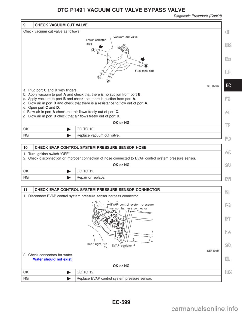
9 CHECK VACUUM CUT VALVE
Check vacuum cut valve as follows:
SEF379Q
a. Plug portCandDwith fingers.
b. Apply vacuum to portAand check that there is no suction from portB.
c. Apply vacuum to portBand check that there is suction from portA.
d. Blow air in portBand check that there is a resistance to flow out of portA.
e. Open portCandD.
f. Blow air in portAcheck that air flows freely out of portC.
g. Blow air in portBcheck that air flows freely out of portD.
OK or NG
OK©GO TO 10.
NG©Replace vacuum cut valve.
10 CHECK EVAP CONTROL SYSTEM PRESSURE SENSOR HOSE
1. Turn ignition switch ªOFFº.
2. Check disconnection or improper connection of hose connected to EVAP control system pressure sensor.
OK or NG
OK©GO TO 11.
NG©Repair or replace.
11 CHECK EVAP CONTROL SYSTEM PRESSURE SENSOR CONNECTOR
1. Disconnect EVAP control system pressure sensor harness connector.
SEF495R
2. Check connectors for water.
Water should not exist.
OK or NG
OK©GO TO 12.
NG©Replace EVAP control system pressure sensor.
GI
MA
EM
LC
FE
AT
TF
PD
AX
SU
BR
ST
RS
BT
HA
SC
EL
IDX
DTC P1491 VACUUM CUT VALVE BYPASS VALVE
Diagnostic Procedure (Cont'd)
EC-599
Page 1135 of 2395
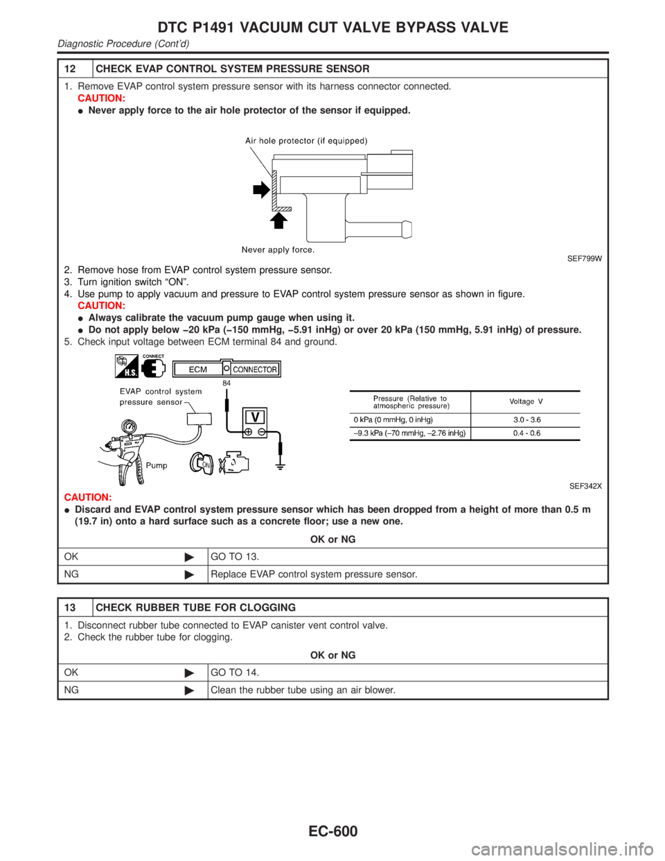
12 CHECK EVAP CONTROL SYSTEM PRESSURE SENSOR
1. Remove EVAP control system pressure sensor with its harness connector connected.
CAUTION:
INever apply force to the air hole protector of the sensor if equipped.
SEF799W
2. Remove hose from EVAP control system pressure sensor.
3. Turn ignition switch ªONº.
4. Use pump to apply vacuum and pressure to EVAP control system pressure sensor as shown in figure.
CAUTION:
IAlways calibrate the vacuum pump gauge when using it.
IDo not apply below þ20 kPa (þ150 mmHg, þ5.91 inHg) or over 20 kPa (150 mmHg, 5.91 inHg) of pressure.
5. Check input voltage between ECM terminal 84 and ground.
SEF342X
CAUTION:
IDiscard and EVAP control system pressure sensor which has been dropped from a height of more than 0.5 m
(19.7 in) onto a hard surface such as a concrete floor; use a new one.
OK or NG
OK©GO TO 13.
NG©Replace EVAP control system pressure sensor.
13 CHECK RUBBER TUBE FOR CLOGGING
1. Disconnect rubber tube connected to EVAP canister vent control valve.
2. Check the rubber tube for clogging.
OK or NG
OK©GO TO 14.
NG©Clean the rubber tube using an air blower.
DTC P1491 VACUUM CUT VALVE BYPASS VALVE
Diagnostic Procedure (Cont'd)
EC-600
Page 1136 of 2395
14 CHECK EVAP CANISTER VENT CONTROL VALVE-I
1. Remove EVAP canister vent control valve from EVAP canister.
2. Check portionBof EVAP canister vent control valve for being rusted.
SEF337X
OK or NG
OK©GO TO 15.
NG©Replace EVAP canister vent control valve.
15 CHECK EVAP CANISTER VENT CONTROL VALVE-II
With CONSULT-II
1. Reconnect harness disconnected connectors.
2. Turn ignition switch ON.
3. Perform ªVENT CONTROL/Vº in ªACTIVE TESTº mode.
4. Check air passage continuity and operation delay time.
SEF991Y
Without CONSULT-II
Check air passage continuity and operation delay time under the following conditions.
SEF339X
Make sure new O-ring is installed properly.
OK or NG
OK©GO TO 17.
NG©GO TO 16.
GI
MA
EM
LC
FE
AT
TF
PD
AX
SU
BR
ST
RS
BT
HA
SC
EL
IDX
DTC P1491 VACUUM CUT VALVE BYPASS VALVE
Diagnostic Procedure (Cont'd)
EC-601
Page 1138 of 2395
Component DescriptionNBEC0361The malfunction information related to A/T (Automatic Transmission) is transferred through the line (circuit)
from TCM (Transmission control module) to ECM. Therefore, be sure to erase the malfunction information such
as DTC not only in TCM (Transmission control module) but also ECM after the A/T related repair.
On Board Diagnosis LogicNBEC0363Malfunction is detected when an incorrect signal from TCM (Trans-
mission control module) is sent to ECM.
Possible CauseNBEC0594IHarness or connectors
[The communication line circuit between ECM and TCM
(Transmission control module) is open or shorted.]
IDead (Weak) battery
ITCM (Transmission control module)
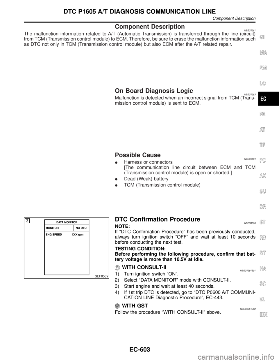
SEF058Y
DTC Confirmation ProcedureNBEC0364NOTE:
If ªDTC Confirmation Procedureº has been previously conducted,
always turn ignition switch ªOFFº and wait at least 10 seconds
before conducting the next test.
TESTING CONDITION:
Before performing the following procedure, confirm that bat-
tery voltage is more than 10.5V at idle.
WITH CONSULT-IINBEC0364S011) Turn ignition switch ªONº.
2) Select ªDATA MONITORº mode with CONSULT-II.
3) Start engine and wait at least 40 seconds.
4) If 1st trip DTC is detected, go to ªDTC P0600 A/T COMMUNI-
CATION LINE Diagnostic Procedureº, EC-443.
WITH GSTNBEC0364S02Follow the procedure ªWITH CONSULT-IIº above.
GI
MA
EM
LC
FE
AT
TF
PD
AX
SU
BR
ST
RS
BT
HA
SC
EL
IDX
DTC P1605 A/T DIAGNOSIS COMMUNICATION LINE
Component Description
EC-603
Page 1139 of 2395
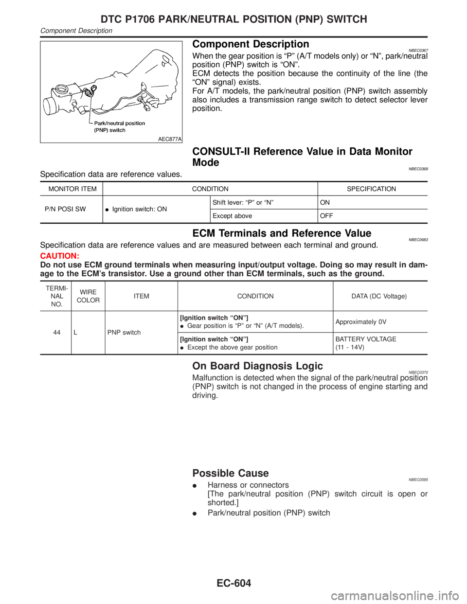
AEC877A
Component DescriptionNBEC0367When the gear position is ªPº (A/T models only) or ªNº, park/neutral
position (PNP) switch is ªONº.
ECM detects the position because the continuity of the line (the
ªONº signal) exists.
For A/T models, the park/neutral position (PNP) switch assembly
also includes a transmission range switch to detect selector lever
position.
CONSULT-II Reference Value in Data Monitor
Mode
NBEC0368Specification data are reference values.
MONITOR ITEM CONDITION SPECIFICATION
P/N POSI SWIIgnition switch: ONShift lever: ªPº or ªNº ON
Except above OFF
ECM Terminals and Reference ValueNBEC0683Specification data are reference values and are measured between each terminal and ground.
CAUTION:
Do not use ECM ground terminals when measuring input/output voltage. Doing so may result in dam-
age to the ECM's transistor. Use a ground other than ECM terminals, such as the ground.
TERMI-
NAL
NO.WIRE
COLORITEM CONDITION DATA (DC Voltage)
44 L PNP switch[Ignition switch ªONº]
IGear position is ªPº or ªNº (A/T models).Approximately 0V
[Ignition switch ªONº]
IExcept the above gear positionBATTERY VOLTAGE
(11 - 14V)
On Board Diagnosis LogicNBEC0370Malfunction is detected when the signal of the park/neutral position
(PNP) switch is not changed in the process of engine starting and
driving.
Possible CauseNBEC0595IHarness or connectors
[The park/neutral position (PNP) switch circuit is open or
shorted.]
IPark/neutral position (PNP) switch
DTC P1706 PARK/NEUTRAL POSITION (PNP) SWITCH
Component Description
EC-604
Page 1140 of 2395

DTC Confirmation ProcedureNBEC0371CAUTION:
Always drive vehicle at a safe speed.
NOTE:
If ªDTC Confirmation Procedureº has been previously conducted,
always turn ignition switch ªOFFº and wait at least 10 seconds
before conducting the next test.
SEF212Y
SEF213Y
WITH CONSULT-IINBEC0371S011) Turn ignition switch ªONº.
2) Select ªP/N POSI SWº in ªDATA MONITORº mode with CON-
SULT-II. Then check the ªP/N POSI SWº signal under the fol-
lowing conditions.
Position (Selector lever) Known-good signal
ªNº and ªPº position ON
Except the above position OFF
If NG, go to ªDiagnostic Procedureº, EC-608.
If OK, go to following step.
3) Select ªDATA MONITORº mode with CONSULT-II.
4) Start engine and warm it up to normal operating temperature.
5) Maintain the following conditions for at least 60 consecutive
seconds.
ENG SPEED 1,500 - 2,500 rpm
COOLAN TEMP/S More than 70ÉC (158ÉF)
B/FUEL SCHDL 3.6 - 12 msec
VHCL SPEED SE 70 - 100 km/h (43 - 62 MPH)
Selector lever Suitable position
6) If 1st trip DTC is detected, go to ªDiagnostic Procedureº,
EC-608.
GI
MA
EM
LC
FE
AT
TF
PD
AX
SU
BR
ST
RS
BT
HA
SC
EL
IDX
DTC P1706 PARK/NEUTRAL POSITION (PNP) SWITCH
DTC Confirmation Procedure
EC-605
Page 1141 of 2395
SEF359X
Overall Function Check=NBEC0372Use this procedure to check the overall function of the park/neutral
position (PNP) switch circuit. During this check, a 1st trip DTC
might not be confirmed.
WITH GSTNBEC0372S011) Turn ignition switch ªONº.
2) Check voltage between ECM terminal 44 and body ground
under the following conditions.
Condition (Gear position) Voltage V (Known good data)
ªPº and ªNº position Approx. 0
Except the above position Battery voltage
3) If NG, go to ªDiagnostic Procedureº, EC-608.
DTC P1706 PARK/NEUTRAL POSITION (PNP) SWITCH
Overall Function Check
EC-606
Page 1143 of 2395
Diagnostic ProcedureNBEC0374
1 CHECK PNP SWITCH GROUND CIRCUIT FOR OPEN AND SHORT
1. Turn ignition switch ªOFFº.
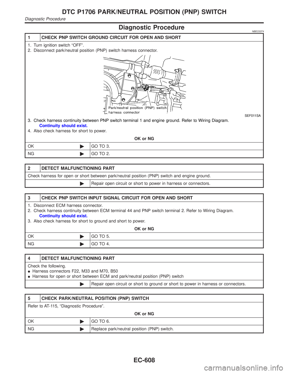
2. Disconnect park/neutral position (PNP) switch harness connector.
SEF011SA
3. Check harness continuity between PNP switch terminal 1 and engine ground. Refer to Wiring Diagram.
Continuity should exist.
4. Also check harness for short to power.
OK or NG
OK©GO TO 3.
NG©GO TO 2.
2 DETECT MALFUNCTIONING PART
Check harness for open or short between park/neutral position (PNP) switch and engine ground.
©Repair open circuit or short to power in harness or connectors.
3 CHECK PNP SWITCH INPUT SIGNAL CIRCUIT FOR OPEN AND SHORT
1. Disconnect ECM harness connector.
2. Check harness continuity between ECM terminal 44 and PNP switch terminal 2. Refer to Wiring Diagram.
Continuity should exist.
3. Also check harness for short to ground and short to power.
OK or NG
OK©GO TO 5.
NG©GO TO 4.
4 DETECT MALFUNCTIONING PART
Check the following.
IHarness connectors F22, M33 and M70, B50
IHarness for open or short between ECM and park/neutral position (PNP) switch
©Repair open circuit or short to ground or short to power in harness or connectors.
5 CHECK PARK/NEUTRAL POSITION (PNP) SWITCH
Refer to AT-115, ªDiagnostic Procedureº.
OK or NG
OK©GO TO 6.
NG©Replace park/neutral position (PNP) switch.
DTC P1706 PARK/NEUTRAL POSITION (PNP) SWITCH
Diagnostic Procedure
EC-608