2001 INFINITI QX4 cooling
[x] Cancel search: coolingPage 1918 of 2395
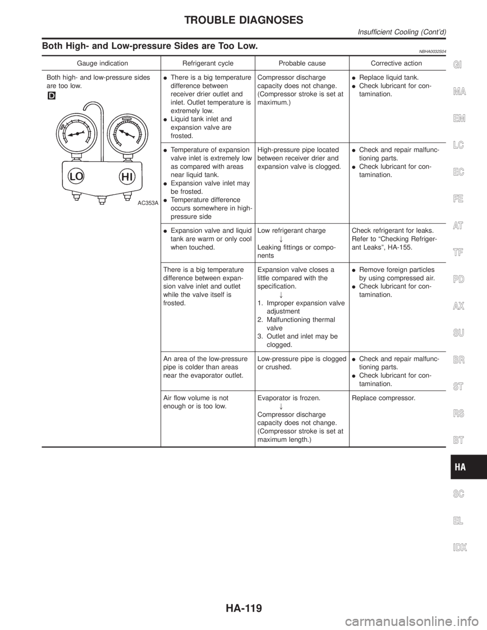
Both High- and Low-pressure Sides are Too Low.NBHA0032S04
Gauge indication Refrigerant cycle Probable cause Corrective action
Both high- and low-pressure sides
are too low.
AC353A
IThere is a big temperature
difference between
receiver drier outlet and
inlet. Outlet temperature is
extremely low.
ILiquid tank inlet and
expansion valve are
frosted.Compressor discharge
capacity does not change.
(Compressor stroke is set at
maximum.)IReplace liquid tank.
ICheck lubricant for con-
tamination.
ITemperature of expansion
valve inlet is extremely low
as compared with areas
near liquid tank.
IExpansion valve inlet may
be frosted.
ITemperature difference
occurs somewhere in high-
pressure sideHigh-pressure pipe located
between receiver drier and
expansion valve is clogged.ICheck and repair malfunc-
tioning parts.
ICheck lubricant for con-
tamination.
IExpansion valve and liquid
tank are warm or only cool
when touched.Low refrigerant charge
"
Leaking fittings or compo-
nentsCheck refrigerant for leaks.
Refer to ªChecking Refriger-
ant Leaksº, HA-155.
There is a big temperature
difference between expan-
sion valve inlet and outlet
while the valve itself is
frosted.Expansion valve closes a
little compared with the
specification.
"
1. Improper expansion valve
adjustment
2. Malfunctioning thermal
valve
3. Outlet and inlet may be
clogged.IRemove foreign particles
by using compressed air.
ICheck lubricant for con-
tamination.
An area of the low-pressure
pipe is colder than areas
near the evaporator outlet.Low-pressure pipe is clogged
or crushed.ICheck and repair malfunc-
tioning parts.
ICheck lubricant for con-
tamination.
Air flow volume is not
enough or is too low.Evaporator is frozen.
"
Compressor discharge
capacity does not change.
(Compressor stroke is set at
maximum length.)Replace compressor.
GI
MA
EM
LC
EC
FE
AT
TF
PD
AX
SU
BR
ST
RS
BT
SC
EL
IDX
TROUBLE DIAGNOSES
Insufficient Cooling (Cont'd)
HA-119
Page 1919 of 2395
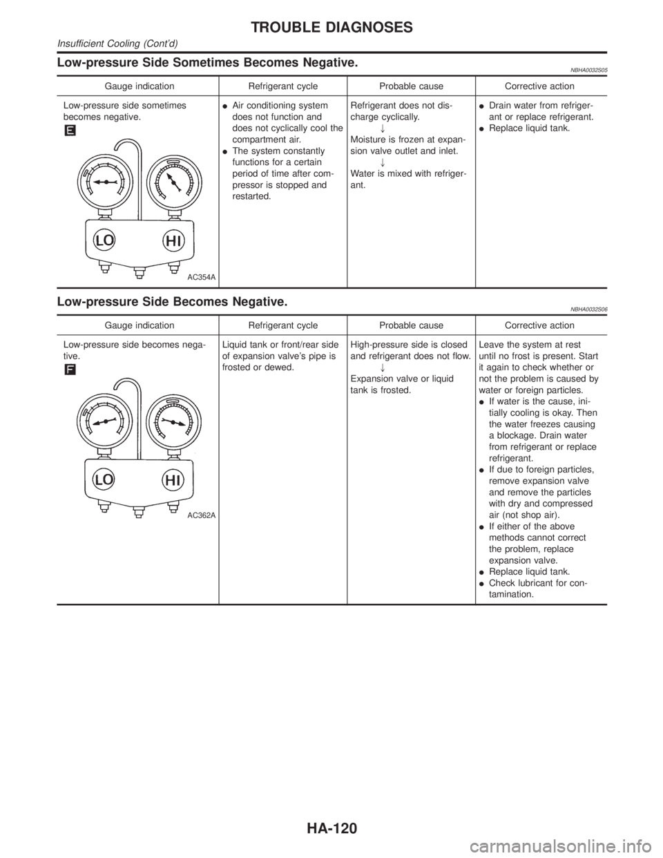
Low-pressure Side Sometimes Becomes Negative.NBHA0032S05
Gauge indication Refrigerant cycle Probable cause Corrective action
Low-pressure side sometimes
becomes negative.
AC354A
IAir conditioning system
does not function and
does not cyclically cool the
compartment air.
IThe system constantly
functions for a certain
period of time after com-
pressor is stopped and
restarted.Refrigerant does not dis-
charge cyclically.
"
Moisture is frozen at expan-
sion valve outlet and inlet.
"
Water is mixed with refriger-
ant.IDrain water from refriger-
ant or replace refrigerant.
IReplace liquid tank.
Low-pressure Side Becomes Negative.NBHA0032S06
Gauge indication Refrigerant cycle Probable cause Corrective action
Low-pressure side becomes nega-
tive.
AC362A
Liquid tank or front/rear side
of expansion valve's pipe is
frosted or dewed.High-pressure side is closed
and refrigerant does not flow.
"
Expansion valve or liquid
tank is frosted.Leave the system at rest
until no frost is present. Start
it again to check whether or
not the problem is caused by
water or foreign particles.
IIf water is the cause, ini-
tially cooling is okay. Then
the water freezes causing
a blockage. Drain water
from refrigerant or replace
refrigerant.
IIf due to foreign particles,
remove expansion valve
and remove the particles
with dry and compressed
air (not shop air).
IIf either of the above
methods cannot correct
the problem, replace
expansion valve.
IReplace liquid tank.
ICheck lubricant for con-
tamination.
TROUBLE DIAGNOSES
Insufficient Cooling (Cont'd)
HA-120
Page 1938 of 2395

SHA930E
RHA584E
Intake Sensor Circuit
COMPONENT DESCRIPTIONNBHA0105Intake SensorNBHA0105S01The intake sensor is located on the cooling unit. It converts tem-
perature of air after it passes through the evaporator into a resis-
tance value which is then input to the auto amp.
After disconnecting intake sensor harness connector, measure
resistance between terminals 1 and 2 at sensor harness side, using
the table below.
Temperature ÉC (ÉF) Resistance kW
þ15 (5) 12.73
þ10 (14) 9.92
þ5 (23) 7.80
0 (32) 6.19
5 (41) 4.95
10 (50) 3.99
15 (59) 3.24
20 (68) 2.65
25 (77) 2.19
30 (86) 1.81
35 (95) 1.51
40 (104) 1.27
45 (113) 1.07
If NG, replace intake sensor.
GI
MA
EM
LC
EC
FE
AT
TF
PD
AX
SU
BR
ST
RS
BT
SC
EL
IDX
TROUBLE DIAGNOSES
Sunload Sensor Circuit (Cont'd)
HA-139
Page 1945 of 2395
Maintenance of Lubricant Quantity in
Compressor
NBHA0071The lubricant in the compressor circulates through the system with
the refrigerant. Add lubricant to compressor when replacing any
component or after a large gas leakage occurred. It is important to
maintain the specified amount.
If lubricant quantity is not maintained properly, the following mal-
functions may result:
ILack of lubricant: May lead to a seized compressor
IExcessive lubricant: Inadequate cooling (thermal exchange
interference)
LUBRICANTNBHA0071S01Name: Nissan A/C System Oil Type S
Part number: KLH00-PAGS0
CHECKING AND ADJUSTINGNBHA0071S02Adjust the lubricant quantity according to the test group shown
below.
1 CHECK LUBRICANT RETURN OPERATION
Can lubricant return operation be performed?
IA/C system works properly.
IThere is no evidence of a large amount of lubricant leakage.
YesorNo
Ye s©GO TO 2.
No©GO TO 3.
2 PERFORM LUBRICANT RETURN OPERATION, PROCEEDING AS FOLLOWS:
1. Start engine, and set the following conditions:
ITest condition
Engine speed: Idling to 1,200 rpm
A/C or AUTO switch: ON
Blower speed: Max. position
Temp. control: Optional [Set so that intake air temperature is 25 to 30ÉC (77 to 86ÉF).]
2.Next item is for V-5 or V-6 compressor. Connect the manifold gauge, and check that the high pressure side
pressure is 588 kPa (6 kg/cm
2, 85 psi) or higher.
If less than the reference level, attach a cover to the front face of the condenser to raise the pressure.
3. Perform lubricant return operation for about 10 minutes.
4. Stop engine.
CAUTION:
If excessive lubricant leakage is noted, do not perform the lubricant return operation.
OK©GO TO 3.
3 CHECK COMPRESSOR
Should the compressor be replaced?
YesorNo
Ye s©Go to ªLubricant Adjustment Procedure for Compressor Replacementº, (HA-148).
No©GO TO 4.
SERVICE PROCEDURE
Maintenance of Lubricant Quantity in Compressor
HA-146
Page 1956 of 2395
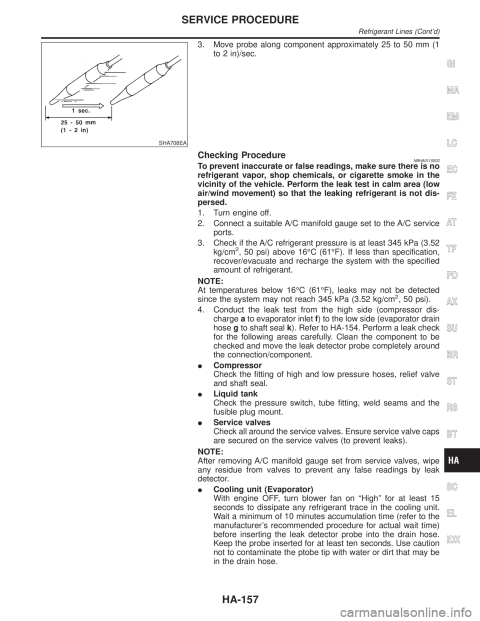
SHA708EA
3. Move probe along component approximately 25 to 50 mm (1
to 2 in)/sec.
Checking ProcedureNBHA0115S02To prevent inaccurate or false readings, make sure there is no
refrigerant vapor, shop chemicals, or cigarette smoke in the
vicinity of the vehicle. Perform the leak test in calm area (low
air/wind movement) so that the leaking refrigerant is not dis-
persed.
1. Turn engine off.
2. Connect a suitable A/C manifold gauge set to the A/C service
ports.
3. Check if the A/C refrigerant pressure is at least 345 kPa (3.52
kg/cm
2, 50 psi) above 16ÉC (61ÉF). If less than specification,
recover/evacuate and recharge the system with the specified
amount of refrigerant.
NOTE:
At temperatures below 16ÉC (61ÉF), leaks may not be detected
since the system may not reach 345 kPa (3.52 kg/cm
2, 50 psi).
4. Conduct the leak test from the high side (compressor dis-
chargeato evaporator inletf) to the low side (evaporator drain
hosegto shaft sealk). Refer to HA-154. Perform a leak check
for the following areas carefully. Clean the component to be
checked and move the leak detector probe completely around
the connection/component.
ICompressor
Check the fitting of high and low pressure hoses, relief valve
and shaft seal.
ILiquid tank
Check the pressure switch, tube fitting, weld seams and the
fusible plug mount.
IService valves
Check all around the service valves. Ensure service valve caps
are secured on the service valves (to prevent leaks).
NOTE:
After removing A/C manifold gauge set from service valves, wipe
any residue from valves to prevent any false readings by leak
detector.
ICooling unit (Evaporator)
With engine OFF, turn blower fan on ªHighº for at least 15
seconds to dissipate any refrigerant trace in the cooling unit.
Wait a minimum of 10 minutes accumulation time (refer to the
manufacturer's recommended procedure for actual wait time)
before inserting the leak detector probe into the drain hose.
Keep the probe inserted for at least ten seconds. Use caution
not to contaminate the ptobe tip with water or dirt that may be
in the drain hose.
GI
MA
EM
LC
EC
FE
AT
TF
PD
AX
SU
BR
ST
RS
BT
SC
EL
IDX
SERVICE PROCEDURE
Refrigerant Lines (Cont'd)
HA-157
Page 1958 of 2395
Belt
TENSION ADJUSTMENTNBHA0079IRefer to MA-13, ªChecking Drive Beltsº.
RHA042G
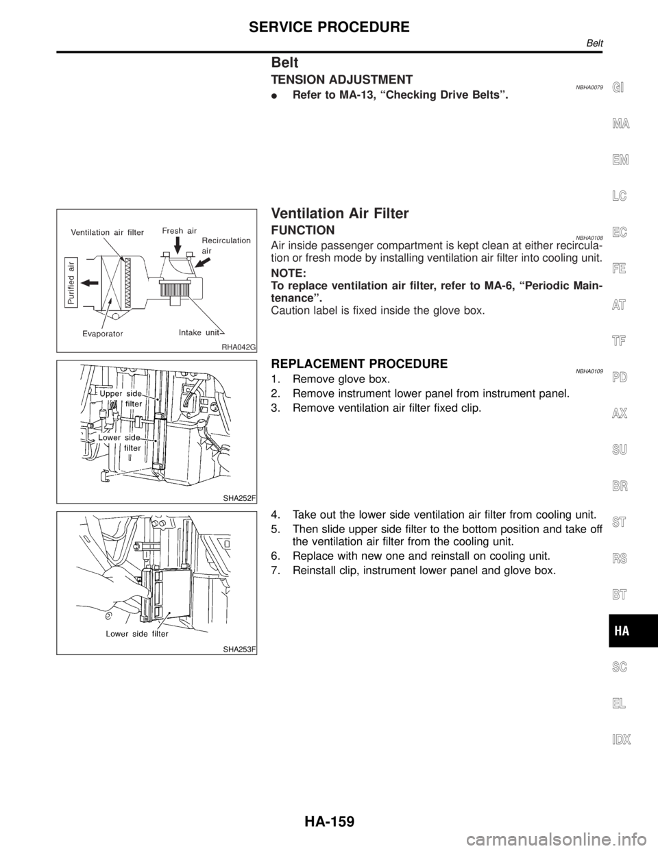
Ventilation Air Filter
FUNCTIONNBHA0108Air inside passenger compartment is kept clean at either recircula-
tion or fresh mode by installing ventilation air filter into cooling unit.
NOTE:
To replace ventilation air filter, refer to MA-6, ªPeriodic Main-
tenanceº.
Caution label is fixed inside the glove box.
SHA252F
REPLACEMENT PROCEDURENBHA01091. Remove glove box.
2. Remove instrument lower panel from instrument panel.
3. Remove ventilation air filter fixed clip.
SHA253F
4. Take out the lower side ventilation air filter from cooling unit.
5. Then slide upper side filter to the bottom position and take off
the ventilation air filter from the cooling unit.
6. Replace with new one and reinstall on cooling unit.
7. Reinstall clip, instrument lower panel and glove box.
GI
MA
EM
LC
EC
FE
AT
TF
PD
AX
SU
BR
ST
RS
BT
SC
EL
IDX
SERVICE PROCEDURE
Belt
HA-159
Page 1962 of 2395
Brake fluid change ...........................................BR-7
Brake fluid level .............................................MA-25
Brake fluid level and line check .......................BR-7
Brake hydraulic line ..........................................BR-9
Brake inspection ............................................MA-25
Brake lines and cables inspection .................MA-25
Brake lining wear temporary checking ..........MA-26
Brake master cylinder ....................................BR-16
Brake pedal ....................................................BR-14
Bulb specifications ........................................EL-456
Bumper, front ..................................................BT-12
Bumper, rear ...................................................BT-15
BYPS/V - Wiring diagram ....................EC-587, 594
C
Camshaft inspection ......................................EM-42
Camshaft position sensor (PHASE) .............EC-342
Canister-See EVAP canister ..........................EC-32
Center bearing assembly (propeller
shaft) .............................................................PD-9
Center bearing disassembly (propeller
shaft) .............................................................PD-7
Center case (Transfer) ..................................TF-123
CHARGE - Wiring diagram ............................SC-20
Charging system ............................................SC-19
Chassis and body maintenance ....................MA-21
CHIME - Wiring diagram...............................EL-127
CIGAR - Wiring diagram ...............................EL-148
Cigarette lighter.............................................EL-148
Circuit breaker.................................................EL-16
CKPS - Wiring diagram ................................EC-334
Closed loop control (Left bank) ....................EC-491
Closed loop control (Right bank) .................EC-491
Closed throttle position switch .....................EC-431
Clutch drum (Transfer) ..................................TF-125
Clutch force release limit adjustment .............TF-39
Clutch pressure switch (Transfer) .................TF-111
Coil spring (front)..............................................SU-8
Coil spring (rear) ............................................SU-18
Collision diagnosis..........................................RS-59
Combination lamp, front, removal and
installation ...................................................BT-12
Combination lamp, rear, removal and
installation ...................................................BT-35
Combination meter..........................................EL-94
Combination meter removal and instal-
lation - See Instrument panel ......................BT-21
Combination switch .........................................EL-28
COMPAS - Wiring diagram ...........................EL-111
Compass .......................................................EL-110
Component Location (auto A/C).....................HA-27
Compression pressure ...................................EM-14
Compressor clutch removal and
installation .................................................HA-150
Compressor precaution ....................................HA-6
Compressor special service tool ....................HA-10
Connecting rod...............................................EM-65
Connecting rod bearing clearance.................EM-69
Connecting rod bushing clearance ................EM-70Connector inspection .......................................GI-21
Console box - See Instrument panel ..............BT-21
CONSULT for ABS .........................................BR-43
CONSULT for all-mode 4WD ..........................TF-30
CONSULT for engine .....................................EC-81
CONSULT-II general information .....................GI-38
Control valve (A/T) ........................................AT-301
Control valve (Transfer) ................................TF-128
Converter housing installation .......................AT-278
Coolant mixture ratio......................................MA-12
Coolant replacement ......................................MA-14
Cooling circuit (engine) ...................................LC-10
``Crankcase emission control system -
See positive crankcase ventilation''............EC-38
Crankshaft ......................................................EM-67
Crankshaft position sensor (POS) ...............EC-334
Crankshaft position sensor (POS)
chipping ....................................................EC-517
Crankshaft position sensor (REF) ................EC-510
Cruise control - See ASCD ...........................EL-221
Cylinder block ................................................EM-61
Cylinder head .................................................EM-38
Cylinder head bolt tightening .........................EM-49
D
Data link connector for Consult......................EC-81
Daytime light system.......................................EL-46
Daytime running light - See Daytime
light system .................................................EL-46
DEF - Wiring diagram ...................................EL-153
Detonation sensor - See Knock sensor .......EC-328
Diagnostic trouble code (DTC) for OBD
system ....................................................EC-8, 60
Diagnostic trouble code (DTC) inspec-
tion priority chart .......................................EC-116
Differential carrier assembly.....................PD-30, 57
Differential carrier disassembly ......................PD-44
Differential gear oil replacement ....................MA-24
Dimensions ......................................................GI-43
D/LOCK - Wiring diagram .............................EL-256
Dome light - See Interior lamp .......................EL-88
Door glass .......................................................BT-18
Door lock .........................................................BT-18
Door mirror ......................................................BT-56
Door trim .........................................................BT-30
Door, front .......................................................BT-18
Door, rear ........................................................BT-20
Drive belt inspection ......................................MA-13
Drive chain (Transfer) ...................................TF-125
Drive pinion diff. inspection ......................PD-23, 47
Drive pinion height ...................................PD-25, 53
Drive plate runout ..........................................EM-70
Drive shaft (front)............................................AX-10
Dropping resistor (A/T) ..................................AT-167
DTC work support ..........................................EC-93
DTRL - Wiring diagram ...................................EL-51
GI
MA
EM
LC
EC
FE
AT
TF
PD
AX
SU
BR
ST
RS
BT
HA
SC
EL
ALPHABETICAL INDEX
IDX-3
Page 1970 of 2395
ENGINE LUBRICATION &
COOLING SYSTEMS
SECTION
LC
CONTENTS
ENGINE LUBRICATION SYSTEM..................................2
Precautions ..................................................................2
LIQUID GASKET APPLICATION PROCEDURE............2
Preparation ..................................................................2
SPECIAL SERVICE TOOLS........................................2
COMMERCIAL SERVICE TOOL..................................3
Lubrication Circuit ........................................................3
Oil Pressure Check......................................................4
Oil Pump ......................................................................5
REMOVAL AND INSTALLATION.................................5
DISASSEMBLY AND ASSEMBLY................................5
OIL PUMP INSPECTION............................................6
REGULATOR VALVE INSPECTION............................6
OIL FILTER...............................................................7
Oil Cooler .....................................................................7
REMOVAL AND INSTALLATION.................................7
INSPECTION.............................................................8
Service Data and Specifications (SDS).......................8
OIL PRESSURE........................................................8
REGULATOR VALVE.................................................8
OIL PUMP.................................................................8
ENGINE COOLING SYSTEM..........................................9
Precautions ..................................................................9
LIQUID GASKET APPLICATION PROCEDURE............9
Preparation ..................................................................9
SPECIAL SERVICE TOOLS........................................9
Cooling Circuit ...........................................................10
System Check............................................................ 11
CHECKING COOLING SYSTEM HOSES................... 11
CHECKING RADIATOR............................................ 11
CHECKING RADIATOR CAP.................................... 11
CHECKING COOLING SYSTEM FOR LEAKS............12
Water Pump ...............................................................12
REMOVAL AND INSTALLATION...............................12
REMOVAL...............................................................12
INSPECTION...........................................................14
INSTALLATION........................................................14
Thermostat .................................................................16
REMOVAL AND INSTALLATION...............................16
INSPECTION...........................................................16
Water Control Valve ...................................................17
REMOVAL AND INSTALLATION...............................17
INSPECTION...........................................................18
Radiator .....................................................................19
REMOVAL AND INSTALLATION...............................19
Cooling Fan (Crankshaft driven) ...............................20
REMOVAL AND INSTALLATION...............................20
INSPECTION...........................................................20
Refilling Engine Coolant ............................................20
Radiator (Aluminum type) ..........................................21
PREPARATION.......................................................21
DISASSEMBLY........................................................21
ASSEMBLY.............................................................22
INSPECTION...........................................................23
Overheating Cause Analysis .....................................24
Service Data and Specifications (SDS).....................25
THERMOSTAT........................................................25
WATER CONTROL VALVE.......................................25
RADIATOR..............................................................25
GI
MA
EM
EC
FE
AT
TF
PD
AX
SU
BR
ST
RS
BT
HA
SC
EL
IDX