2001 INFINITI QX4 tow
[x] Cancel search: towPage 2012 of 2395
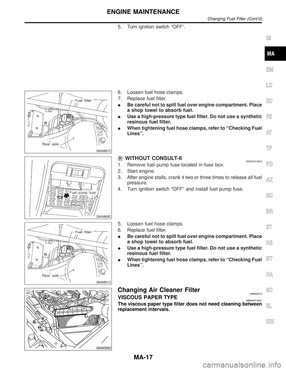
5. Turn ignition switch ªOFFº.
SMA861C
6. Loosen fuel hose clamps.
7. Replace fuel filter.
IBe careful not to spill fuel over engine compartment. Place
a shop towel to absorb fuel.
IUse a high-pressure type fuel filter. Do not use a synthetic
resinous fuel filter.
IWhen tightening fuel hose clamps, refer to ªChecking Fuel
Linesº.
SMA869C
WITHOUT CONSULT-IINBMA0013S021. Remove fuel pump fuse located in fuse box.
2. Start engine.
3. After engine stalls, crank it two or three times to release all fuel
pressure.
4. Turn ignition switch ªOFFº and install fuel pump fuse.
SMA861C
5. Loosen fuel hose clamps.
6. Replace fuel filter.
IBe careful not to spill fuel over engine compartment. Place
a shop towel to absorb fuel.
IUse a high-pressure type fuel filter. Do not use a synthetic
resinous fuel filter.
IWhen tightening fuel hose clamps, refer to ªChecking Fuel
Linesº.
SMA095D
Changing Air Cleaner FilterNBMA0014VISCOUS PAPER TYPENBMA0014S01The viscous paper type filter does not need cleaning between
replacement intervals.
GI
EM
LC
EC
FE
AT
TF
PD
AX
SU
BR
ST
RS
BT
HA
SC
EL
IDX
ENGINE MAINTENANCE
Changing Fuel Filter (Cont'd)
MA-17
Page 2034 of 2395
SPD131
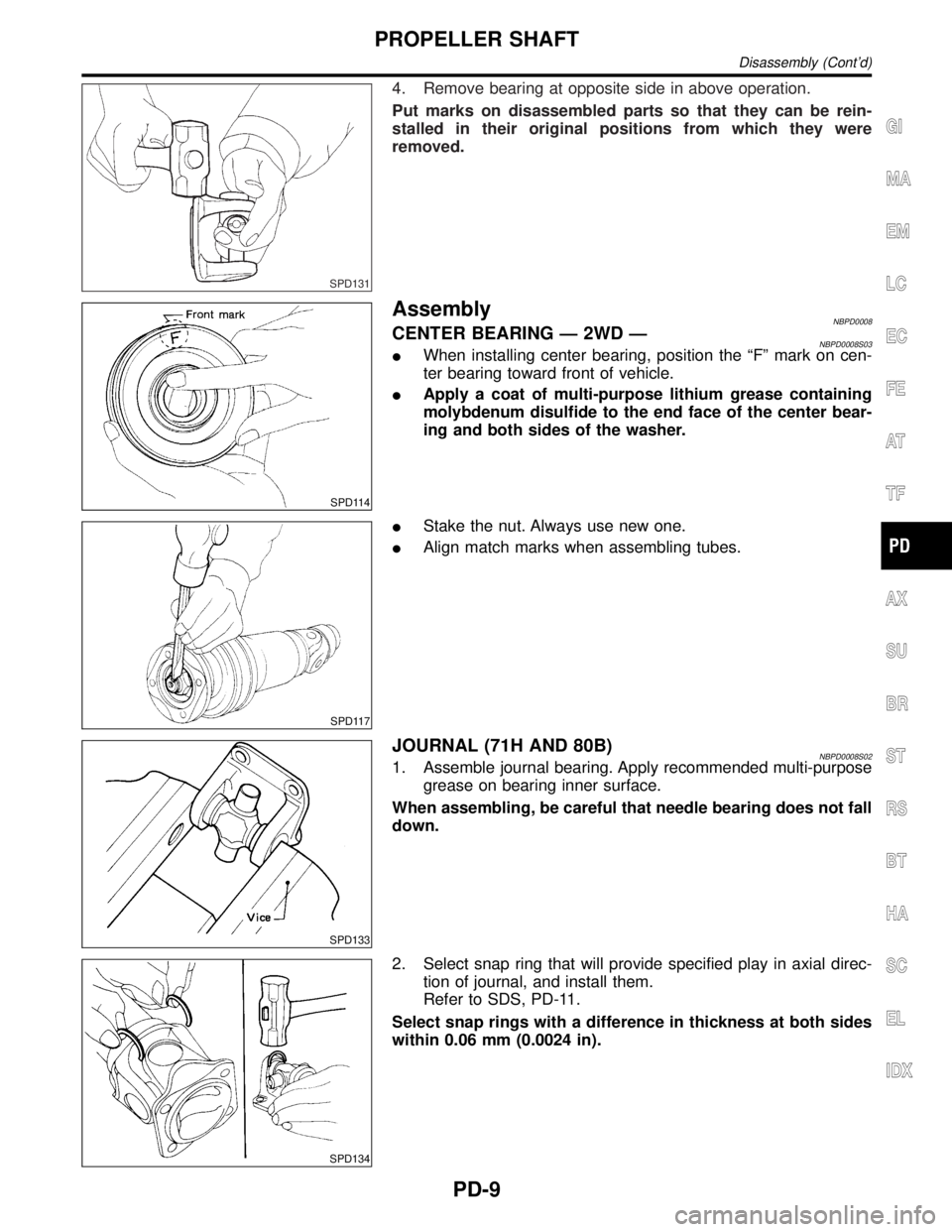
4. Remove bearing at opposite side in above operation.
Put marks on disassembled parts so that they can be rein-
stalled in their original positions from which they were
removed.
SPD114
AssemblyNBPD0008CENTER BEARING Ð 2WD ÐNBPD0008S03IWhen installing center bearing, position the ªFº mark on cen-
ter bearing toward front of vehicle.
IApply a coat of multi-purpose lithium grease containing
molybdenum disulfide to the end face of the center bear-
ing and both sides of the washer.
SPD117
IStake the nut. Always use new one.
IAlign match marks when assembling tubes.
SPD133
JOURNAL (71H AND 80B)NBPD0008S021. Assemble journal bearing. Apply recommended multi-purpose
grease on bearing inner surface.
When assembling, be careful that needle bearing does not fall
down.
SPD134
2. Select snap ring that will provide specified play in axial direc-
tion of journal, and install them.
Refer to SDS, PD-11.
Select snap rings with a difference in thickness at both sides
within 0.06 mm (0.0024 in).
GI
MA
EM
LC
EC
FE
AT
TF
AX
SU
BR
ST
RS
BT
HA
SC
EL
IDX
PROPELLER SHAFT
Disassembly (Cont'd)
PD-9
Page 2093 of 2395
Front Seat Belt
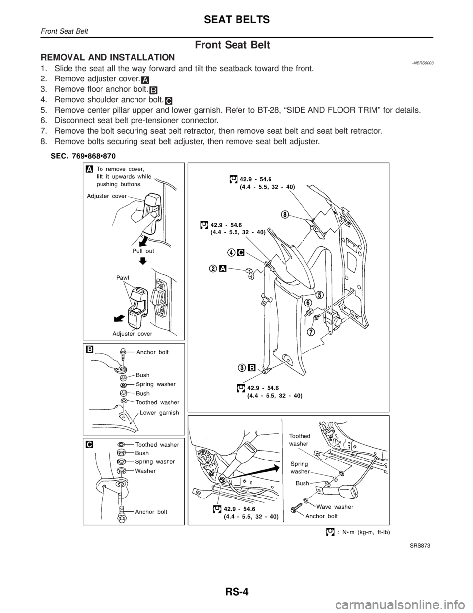
REMOVAL AND INSTALLATION=NBRS00031. Slide the seat all the way forward and tilt the seatback toward the front.
2. Remove adjuster cover.
3. Remove floor anchor bolt.
4. Remove shoulder anchor bolt.
5. Remove center pillar upper and lower garnish. Refer to BT-28, ªSIDE AND FLOOR TRIMº for details.
6. Disconnect seat belt pre-tensioner connector.
7. Remove the bolt securing seat belt retractor, then remove seat belt and seat belt retractor.
8. Remove bolts securing seat belt adjuster, then remove seat belt adjuster.
SRS873
SEAT BELTS
Front Seat Belt
RS-4
Page 2099 of 2395
Precautions
SUPPLEMENTAL RESTRAINT SYSTEM (SRS) ªAIR BAGº AND ªSEAT BELT
PRE-TENSIONERº
NBRS0005The Supplemental Restraint System such as ªAIR BAGº and ªSEAT BELT PRE-TENSIONERº used along with
a seat belt, helps to reduce the risk or severity of injury to the driver and front passenger for certain types of
collision. The SRS composition which is available to INFINITI QX4 is as follows:
IFor a frontal collision
The Supplemental Restraint System consists of driver air bag module (located in the center of the steer-
ing wheel), front passenger air bag module (located on the instrument panel on passenger side), seat belt
pre-tensioners, a diagnosis sensor unit, warning lamp, wiring harness and spiral cable.
IFor a side collision
The Supplemental Restraint System consists of side air bag module (located in the outer side of front seat),
satellite sensor, diagnosis sensor unit (one of components of air bags for a frontal collision), wiring harness,
warning lamp (one of components of air bags for a frontal collision).
WARNING:
ITo avoid rendering the SRS inoperative, which could increase the risk of personal injury or death
in the event of a collision which would result in air bag inflation, all maintenance must be performed
by an authorized INFINITI dealer.
IImproper maintenance, including incorrect removal and installation of the SRS, can lead to per-
sonal injury caused by unintentional activation of the system.
IDo not use electrical test equipment on any circuit related to the SRS unless instructed to in this
Service Manual. Spiral cable and wiring harnesses covered with yellow insulation tape either just
before the harness connectors or for the complete harness are related to the SRS.
PRECAUTIONS FOR SRS ªAIR BAGº AND ªSEAT BELT PRE-TENSIONERº SERVICENBRS0006IDo not use electrical test equipment to check SRS circuits unless instructed to in this Service Manual.
IBefore servicing the SRS, turn ignition switch ªOFFº, disconnect both battery cables and wait at least 3
minutes.
For approximately 3 minutes after the cables are removed, it is still possible for the air bag and seat belt
pre-tensioner to deploy. Therefore, do not work on any SRS connectors or wires until at least 3 minutes
have passed.
IDiagnosis sensor unit must always be installed with their arrow marks ªgº pointing towards the front of
the vehicle for proper operation. Also check diagnosis sensor unit for cracks, deformities or rust before
installation and replace as required.
IThe spiral cable must be aligned with the neutral position since its rotations are limited. Do not attempt to
turn steering wheel or column after removal of steering gear.
IHandle air bag module carefully. Always place driver and passenger air bag modules with the pad side
facing upward and side air bag module (built-in type) standing with the stud bolt side setting bottom.
IConduct self-diagnosis to check entire SRS for proper function after replacing any components.
IAfter air bag inflates, the front instrument panel assembly should be replaced if damaged.
WIRING DIAGRAMS AND TROUBLE DIAGNOSISNBRS0007When you read wiring diagrams, refer to the following:
IGI-11, ªHOW TO READ WIRING DIAGRAMSº
IEL-9, ªPOWER SUPPLY ROUTINGº for power distribution circuit
When you perform trouble diagnosis, refer to the following:
IGI-35, ªHOW TO FOLLOW TEST GROUPS IN TROUBLE DIAGNOSESº
IGI-24, ªHOW TO PERFORM EFFICIENT DIAGNOSIS FOR AN ELECTRICAL INCIDENTº
SUPPLEMENTAL RESTRAINT SYSTEM (SRS)
Precautions
RS-10
Page 2183 of 2395
Supplemental Restraint System (SRS) ªAIR
BAGº and ªSEAT BELT PRE-TENSIONERº
NBST0044The Supplemental Restraint System such as ªAIR BAGº and ªSEAT BELT PRE-TENSIONERº used along with
a seat belt, helps to reduce the risk or severity of injury to the driver and front passenger for certain types of
collision. The SRS system composition which is available to INFINITI QX4 is as follows:
IFor a frontal collision
The Supplemental Restraint System consists of driver air bag module (located in the center of the steer-
ing wheel), front passenger air bag module (located on the instrument panel on passenger side), seat belt
pre-tensioners, a diagnosis sensor unit, warning lamp, wiring harness and spiral cable.
IFor a side collision
The Supplemental Restraint System consists of side air bag module (located in the outer side of front seat),
satellite sensor, diagnosis sensor unit (one of components of air bags for a frontal collision), wiring harness,
warning lamp (one of components of air bags for a frontal collision).
Information necessary to service the system safely is included in theRS sectionof this Service Manual.
WARNING:
ITo avoid rendering the SRS inoperative, which could increase the risk of personal injury or death
in the event of a collision which would result in air bag inflation, all maintenance must be performed
by an authorized INFINITI dealer.
IImproper maintenance, including incorrect removal and installation of the SRS, can lead to per-
sonal injury caused by unintentional activation of the system. For removal of Spiral Cable and Air
Bag Module, see the RS section.
IDo not use electrical test equipment on any circuit related to the SRS unless instructed to in this
Service Manual. Spiral cable and wiring harnesses covered with yellow insulation tape either just
before the harness connectors or for the complete harness are related to the SRS.
Precautions for Steering SystemNBST0002IBefore disassembly, thoroughly clean the outside of the unit.
IDisassembly should be done in a clean work area. It is important to prevent the internal parts from
becoming contaminated by dirt or other foreign matter.
IPlace disassembled parts in order, on a parts rack, for easier and proper assembly.
IUse nylon cloths or paper towels to clean the parts; common shop rags can leave lint that might
interfere with their operation.
IBefore inspection or reassembly, carefully clean all parts with a general purpose, non-flammable
solvent.
IBefore assembly, apply a coat of recommended power steering fluid* to hydraulic parts. Vaseline
may be applied to O-rings and seals. Do not use any grease.
IReplace all gaskets, seals and O-rings. Avoid damaging O-rings, seals and gaskets during instal-
lation. Perform functional tests whenever designated.
*: Genuine Nissan PSF II or equivalent. Refer to MA-11, ªFluids and Lubricantsº.
PRECAUTIONS
Supplemental Restraint System (SRS) ªAIR BAGº and ªSEAT BELT PRE-TENSIONERº
ST-2
Page 2209 of 2395
DisassemblyNBST0034CAUTION:
IParts which can be disassembled are strictly limited.
Never disassemble parts other than those specified.
IDisassemble in as clean a place as possible.
IClean your hands before disassembly.
IDo not use rags; use nylon cloths or paper towels.
IFollow the procedures and cautions in the Service
Manual.
IWhen disassembling and reassembling, do not let foreign
matter enter or contact the parts.
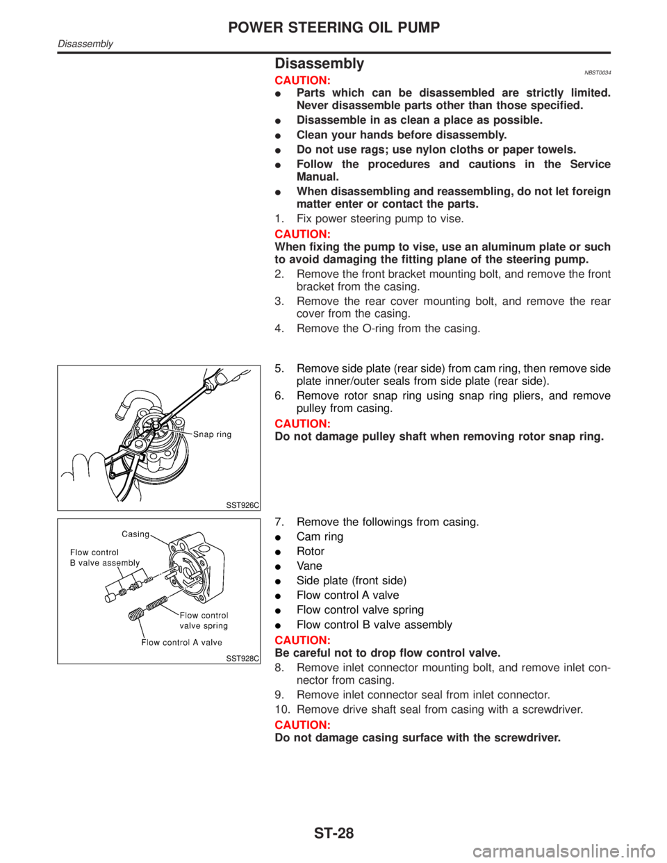
1. Fix power steering pump to vise.
CAUTION:
When fixing the pump to vise, use an aluminum plate or such
to avoid damaging the fitting plane of the steering pump.
2. Remove the front bracket mounting bolt, and remove the front
bracket from the casing.
3. Remove the rear cover mounting bolt, and remove the rear
cover from the casing.
4. Remove the O-ring from the casing.
SST926C
5. Remove side plate (rear side) from cam ring, then remove side
plate inner/outer seals from side plate (rear side).
6. Remove rotor snap ring using snap ring pliers, and remove
pulley from casing.
CAUTION:
Do not damage pulley shaft when removing rotor snap ring.
SST928C
7. Remove the followings from casing.
ICam ring
IRotor
IVane
ISide plate (front side)
IFlow control A valve
IFlow control valve spring
IFlow control B valve assembly
CAUTION:
Be careful not to drop flow control valve.
8. Remove inlet connector mounting bolt, and remove inlet con-
nector from casing.
9. Remove inlet connector seal from inlet connector.
10. Remove drive shaft seal from casing with a screwdriver.
CAUTION:
Do not damage casing surface with the screwdriver.
POWER STEERING OIL PUMP
Disassembly
ST-28
Page 2211 of 2395
SST930C
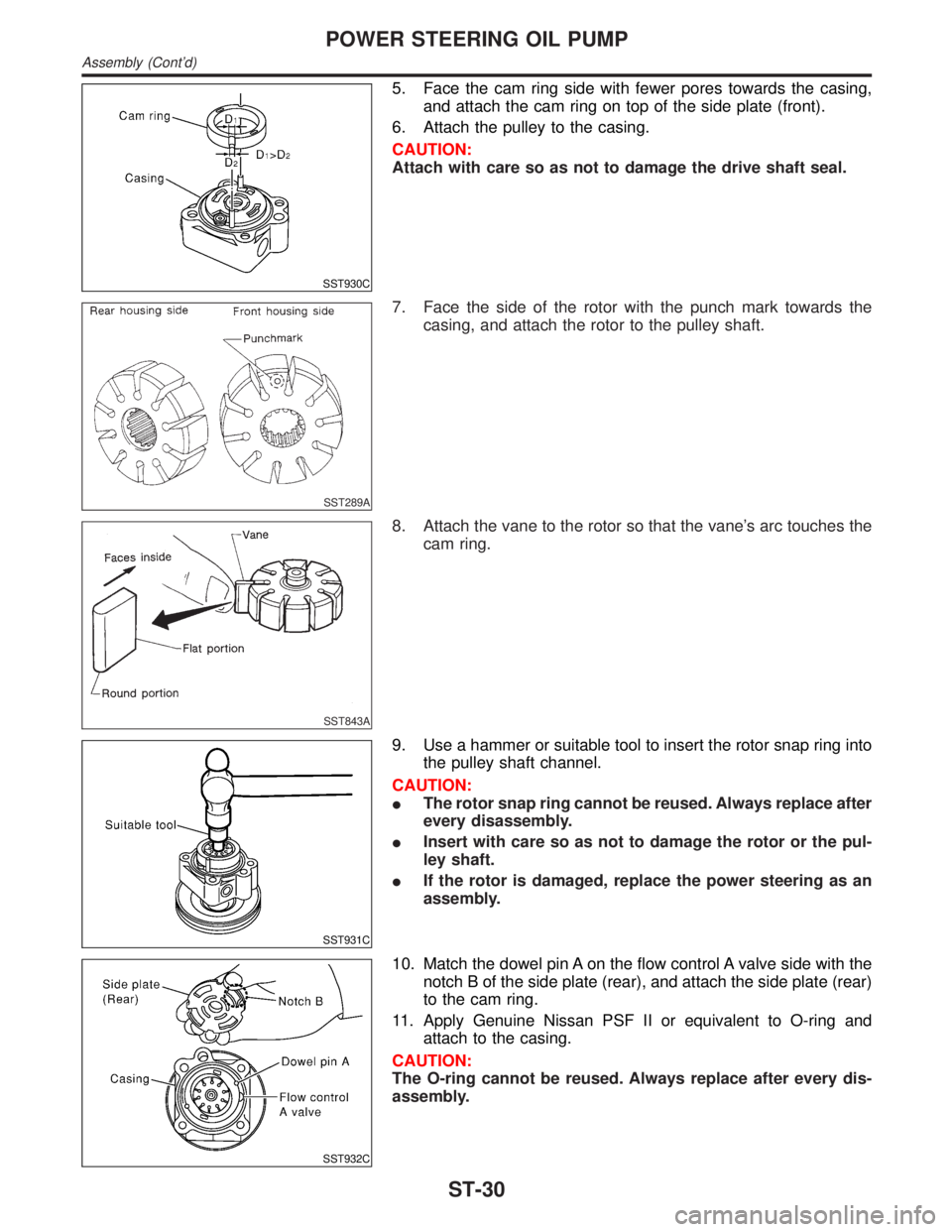
5. Face the cam ring side with fewer pores towards the casing,
and attach the cam ring on top of the side plate (front).
6. Attach the pulley to the casing.
CAUTION:
Attach with care so as not to damage the drive shaft seal.
SST289A
7. Face the side of the rotor with the punch mark towards the
casing, and attach the rotor to the pulley shaft.
SST843A
8. Attach the vane to the rotor so that the vane's arc touches the
cam ring.
SST931C
9. Use a hammer or suitable tool to insert the rotor snap ring into
the pulley shaft channel.
CAUTION:
IThe rotor snap ring cannot be reused. Always replace after
every disassembly.
IInsert with care so as not to damage the rotor or the pul-
ley shaft.
IIf the rotor is damaged, replace the power steering as an
assembly.
SST932C
10. Match the dowel pin A on the flow control A valve side with the
notch B of the side plate (rear), and attach the side plate (rear)
to the cam ring.
11. Apply Genuine Nissan PSF II or equivalent to O-ring and
attach to the casing.
CAUTION:
The O-ring cannot be reused. Always replace after every dis-
assembly.
POWER STEERING OIL PUMP
Assembly (Cont'd)
ST-30
Page 2239 of 2395

MEF040DB
IBefore replacing Transfer control unit, perform Transfer
control unit input/output signal inspection and make sure
whether Transfer control unit functions properly or not.
(See page TF-55.)
Service NoticeNBTF00021) Before proceeding with disassembly, thoroughly clean the outside of the all-mode 4WD transfer. It is
important to prevent the internal parts from becoming contaminated by dirt or other foreign matter.
2) Disassembly should be done in a clean work area.
3) Use lint-free cloth or towels for wiping parts clean. Common shop rags can leave fibers that could inter-
fere with the operation of the all-mode 4WD transfer.
4) Place disassembled parts in order for easier and proper assembly.
5) All parts should be carefully cleaned with a general purpose, non-flammable solvent before inspection or
reassembly.
6) Gaskets, seals and O-rings should be replaced any time the all-mode 4WD transfer is disassembled.
7) It is very important to perform functional tests whenever they are indicated.
8) The valve body contains precision parts and requires extreme care when parts are removed and serviced.
Place removed parts in a parts rack in order to replace them in correct positions and sequences. Care will
also prevent springs and small parts from becoming scattered or lost.
9) Properly installed valves, sleeves, plugs, etc. will slide along bores in valve body under their own weight.
10) Before assembly, apply a coat of recommended ATF to all parts. Apply petroleum jelly to protect O-rings
and seals, and to hold bearings and washers in place during assembly. Do not use grease.
11) Extreme care should be taken to avoid damage to O-rings, seals and gaskets when assembling.
12) After overhaul, refill the transfer with new ATF.
13) When the all-mode 4WD transfer drain plug is removed, only some of the fluid is drained. Old all-mode
4WD transfer fluid will remain in torque converter and ATF cooling system. Always follow the procedures,
MA-22, ªChanging All-mode 4WD Transfer Fluidº.
Wiring Diagrams and Trouble DiagnosisNBTF0003When you read wiring diagrams, refer to the following:
IGI-11, ªHOW TO READ WIRING DIAGRAMSº
IEL-9, ªPOWER SUPPLY ROUTINGº
When you perform trouble diagnosis, refer to the following:
IGI-35, ªHOW TO FOLLOW TEST GROUPS IN TROUBLE DIAGNOSISº
IGI-24, ªHOW TO PERFORM EFFICIENT DIAGNOSIS FOR AN ELECTRICAL INCIDENTº
PRECAUTIONS
Precautions (Cont'd)
TF-4