Page 1357 of 2395
MEL037G
2. Withdraw antenna rod while raising it by operating antenna
motor.
MEL038G
INSTALLATIONNBEL0088S021. Lower antenna rod by operating antenna motor.
2. Insert gear section of antenna rope into place with it facing
toward antenna motor.
3. As soon as antenna rope is wound on antenna motor, stop
antenna motor. Insert antenna rod lower end into antenna
motor pipe.
4. Retract antenna rod completely by operating antenna motor.
5. Install antenna nut and base.
AUDIO ANTENNA
Antenna Rod Replacement (Cont'd)
EL-172
Page 1613 of 2395

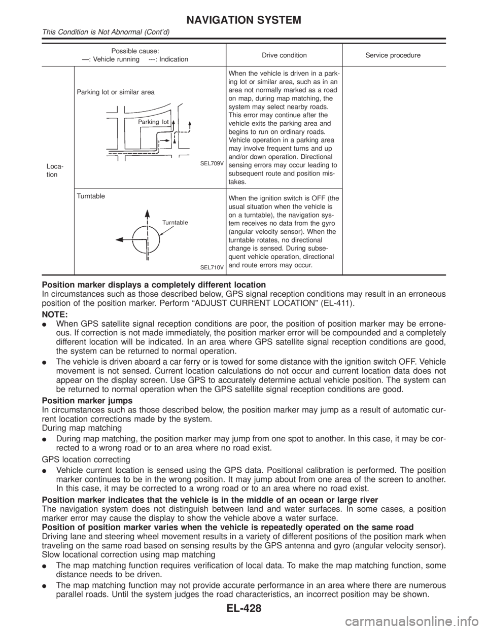
Possible cause:
Ð: Vehicle running ---: IndicationDrive condition Service procedure
Loca-
tionParking lot or similar area
SEL709V
When the vehicle is driven in a park-
ing lot or similar area, such as in an
area not normally marked as a road
on map, during map matching, the
system may select nearby roads.
This error may continue after the
vehicle exits the parking area and
begins to run on ordinary roads.
Vehicle operation in a parking area
may involve frequent turns and up
and/or down operation. Directional
sensing errors may occur leading to
subsequent route and position mis-
takes.
Turntable
SEL710V
When the ignition switch is OFF (the
usual situation when the vehicle is
on a turntable), the navigation sys-
tem receives no data from the gyro
(angular velocity sensor). When the
turntable rotates, no directional
change is sensed. During subse-
quent vehicle operation, directional
and route errors may occur.
Position marker displays a completely different location
In circumstances such as those described below, GPS signal reception conditions may result in an erroneous
position of the position marker. Perform ªADJUST CURRENT LOCATIONº (EL-411).
NOTE:
IWhen GPS satellite signal reception conditions are poor, the position of position marker may be errone-
ous. If correction is not made immediately, the position marker error will be compounded and a completely
different location will be indicated. In an area where GPS satellite signal reception conditions are good,
the system can be returned to normal operation.
IThe vehicle is driven aboard a car ferry or is towed for some distance with the ignition switch OFF. Vehicle
movement is not sensed. Current location calculations do not occur and current location data does not
appear on the display screen. Use GPS to accurately determine actual vehicle position. The system can
be returned to normal operation when the GPS satellite signal reception conditions are good.
Position marker jumps
In circumstances such as those described below, the position marker may jump as a result of automatic cur-
rent location corrections made by the system.
During map matching
IDuring map matching, the position marker may jump from one spot to another. In this case, it may be cor-
rected to a wrong road or to an area where no road exist.
GPS location correcting
IVehicle current location is sensed using the GPS data. Positional calibration is performed. The position
marker continues to be in the wrong position. It may jump about from one area of the screen to another.
In this case, it may be corrected to a wrong road or to an area where no road exist.
Position marker indicates that the vehicle is in the middle of an ocean or large river
The navigation system does not distinguish between land and water surfaces. In some cases, a position
marker error may cause the display to show the vehicle above a water surface.
Position of position marker varies when the vehicle is repeatedly operated on the same road
Driving lane and steering wheel movement results in a variety of different positions of the position mark when
traveling on the same road based on sensing results by the GPS antenna and gyro (angular velocity sensor).
Slow locational correction using map matching
IThe map matching function requires verification of local data. To make the map matching function, some
distance needs to be driven.
IThe map matching function may not provide accurate performance in an area where there are numerous
parallel roads. Until the system judges the road characteristics, an incorrect position may be shown.
NAVIGATION SYSTEM
This Condition is Not Abnormal (Cont'd)
EL-428
Page 1690 of 2395
SEM867E
Lifter guide bore diameter:
35.000 - 35.021 mm (1.3780 - 1.3788 in)
SEM085D
AssemblyNBEM00201. Install valve component parts.
IAlways use new valve oil seal. Refer to ªVALVE OIL
SEALº, EM-35.
IBefore installing valve oil seal, install valve spring seat.
IInstall valve spring (uneven pitch type) with its narrow
pitch side toward cylinder head side (paint mark).
IAfter installing valve component parts, tap valve stem tip with
plastic hammer to assure a proper fit.
SEM891E
InstallationNBEM00211. Before installing rear timing chain case, remove old liquid gas-
ket from mating surface using a scraper.
IAlso remove old liquid gasket from mating surface of cylinder
block.
SEM161F
IRemove old liquid gasket from the bolt hole and thread.
SEM892E
2. Before installing cam bracket, remove old liquid gasket from
mating surface using a scraper.
GI
MA
LC
EC
FE
AT
TF
PD
AX
SU
BR
ST
RS
BT
HA
SC
EL
IDX
CYLINDER HEAD
Inspection (Cont'd)
EM-47
Page 1691 of 2395
SEM532G
3. Before installing the cylinder head gasket, be sure that No. 1
cylinder is at TDC.
IAt this time, the crankshaft key should face toward the right
bank.
SEM445G
4. Install cylinder heads with new gaskets.
IDo not rotate crankshaft and camshaft separately, or
valves will strike piston heads.
SEM957E
CAUTION:
Cylinder head bolts are tightened by plastic zone tightening
method. Whenever the size difference between d1 and d2
exceeds the limit, replace them with new ones.
Limit (d1 - d2):
0.11 mm (0.0043 in)
ILubricate threads and seat surfaces of the bolts with new
engine oil.
CYLINDER HEAD
Installation (Cont'd)
EM-48
Page 1698 of 2395

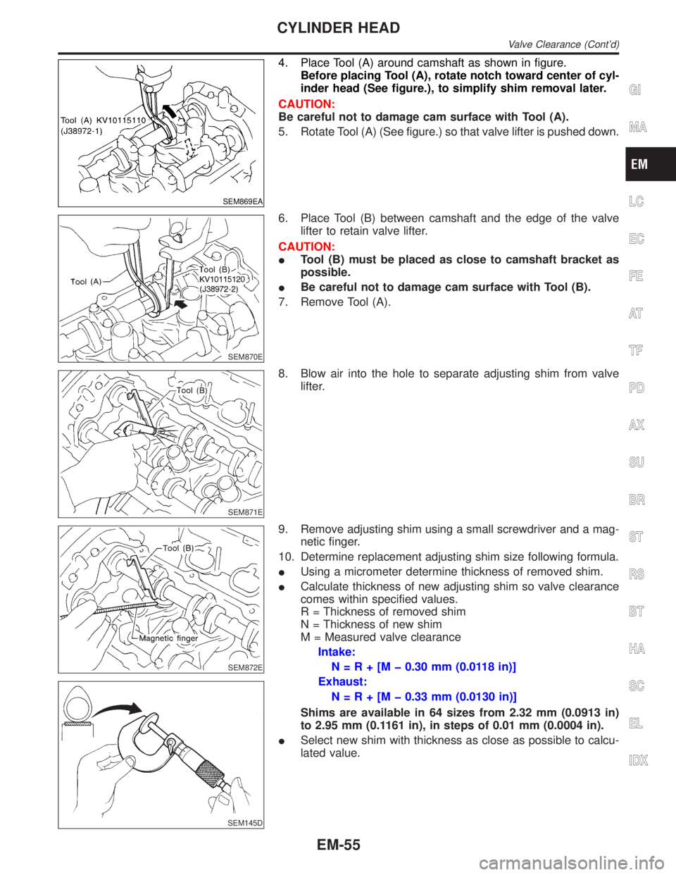
SEM869EA
4. Place Tool (A) around camshaft as shown in figure.
Before placing Tool (A), rotate notch toward center of cyl-
inder head (See figure.), to simplify shim removal later.
CAUTION:
Be careful not to damage cam surface with Tool (A).
5. Rotate Tool (A) (See figure.) so that valve lifter is pushed down.
SEM870E
6. Place Tool (B) between camshaft and the edge of the valve
lifter to retain valve lifter.
CAUTION:
ITool (B) must be placed as close to camshaft bracket as
possible.
IBe careful not to damage cam surface with Tool (B).
7. Remove Tool (A).
SEM871E
8. Blow air into the hole to separate adjusting shim from valve
lifter.
SEM872E
SEM145D
9. Remove adjusting shim using a small screwdriver and a mag-
netic finger.
10. Determine replacement adjusting shim size following formula.
IUsing a micrometer determine thickness of removed shim.
ICalculate thickness of new adjusting shim so valve clearance
comes within specified values.
R = Thickness of removed shim
N = Thickness of new shim
M = Measured valve clearance
Intake:
N=R+[Mþ0.30 mm (0.0118 in)]
Exhaust:
N=R+[Mþ0.33 mm (0.0130 in)]
Shims are available in 64 sizes from 2.32 mm (0.0913 in)
to 2.95 mm (0.1161 in), in steps of 0.01 mm (0.0004 in).
ISelect new shim with thickness as close as possible to calcu-
lated value.
GI
MA
LC
EC
FE
AT
TF
PD
AX
SU
BR
ST
RS
BT
HA
SC
EL
IDX
CYLINDER HEAD
Valve Clearance (Cont'd)
EM-55
Page 1700 of 2395

Removal and InstallationNBEM0042WARNING:
ISituate vehicle on a flat and solid surface.
IPlace chocks at front and back of rear wheels.
IDo not remove engine until exhaust system has com-
pletely cooled off. Otherwise, you may burn yourself
and/or fire may break out in fuel line.
IFor safety during subsequent steps, the tension of wires
should be slackened against the engine.
IBefore disconnecting fuel hose, release fuel pressure
from fuel line.
Refer to EC-39, ªFuel Pressure Releaseº.
IBefore removing front axle from transmission, place
safety stands under designated front supporting points.
Refer to GI section for lifting points and towing.
IBe sure to hoist engine and transmission in a safe man-
ner.
IFor engines not equipped with engine slingers, attach
proper slingers and bolts described in PARTS CATALOG.
CAUTION:
IWhen lifting engine, be careful not to strike adjacent parts,
especially accelerator wire casing, brake lines, and brake
master cylinder.
IIn hoisting the engine, always use engine slingers in a
safe manner.
IBefore separating engine and transmission, remove
crankshaft position sensor (POS) from the assembly.
IAlways take extra care not to damage edge of crankshaft
position sensor (POS), or ring gear teeth.GI
MA
LC
EC
FE
AT
TF
PD
AX
SU
BR
ST
RS
BT
HA
SC
EL
IDX
ENGINE ASSEMBLY
Removal and Installation
EM-57
Page 1716 of 2395

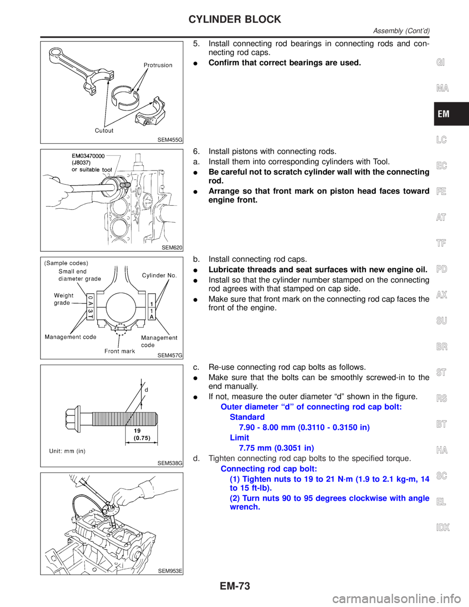
SEM455G
5. Install connecting rod bearings in connecting rods and con-
necting rod caps.
IConfirm that correct bearings are used.
SEM620
6. Install pistons with connecting rods.
a. Install them into corresponding cylinders with Tool.
IBe careful not to scratch cylinder wall with the connecting
rod.
IArrange so that front mark on piston head faces toward
engine front.
SEM457G
b. Install connecting rod caps.
ILubricate threads and seat surfaces with new engine oil.
IInstall so that the cylinder number stamped on the connecting
rod agrees with that stamped on cap side.
IMake sure that front mark on the connecting rod cap faces the
front of the engine.
SEM538G
SEM953E
c. Re-use connecting rod cap bolts as follows.
IMake sure that the bolts can be smoothly screwed-in to the
end manually.
IIf not, measure the outer diameter ªdº shown in the figure.
Outer diameter ªdº of connecting rod cap bolt:
Standard
7.90 - 8.00 mm (0.3110 - 0.3150 in)
Limit
7.75 mm (0.3051 in)
d. Tighten connecting rod cap bolts to the specified torque.
Connecting rod cap bolt:
(1) Tighten nuts to 19 to 21 N´m (1.9 to 2.1 kg-m, 14
to 15 ft-lb).
(2) Turn nuts 90 to 95 degrees clockwise with angle
wrench.
GI
MA
LC
EC
FE
AT
TF
PD
AX
SU
BR
ST
RS
BT
HA
SC
EL
IDX
CYLINDER BLOCK
Assembly (Cont'd)
EM-73
Page 1747 of 2395
Wheels & Tires ..........................................................44
LIFTING POINTS AND TOW TRUCK TOWING...........45
Screw Jack ................................................................45
Garage Jack and Safety Stand .................................46
2-pole Lift ...................................................................47
Tow Truck Towing ......................................................472WD MODELS.........................................................48
4WD MODELS.........................................................48
VEHICLE RECOVERY..............................................49
TIGHTENING TORQUE OF STANDARD BOLTS........50
SAE J1930 TERMINOLOGY LIST................................51
SAE J1930 Terminology List .....................................51
CONTENTS(Cont'd)
GI-2