Page 1854 of 2395

STEP-BY-STEP PROCEDURENBHA0021S05With Navigation SystemNBHA0021S0501
1 SET IN SELF-DIAGNOSTIC MODE
1. Turn ignition switch ON.
2. Set in self-diagnostic mode as follows. Within 10 seconds after starting engine (ignition switch is turned ªONº.), press
switch for at least 5 seconds.
©GO TO 2.
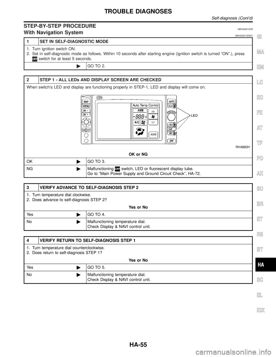
2 STEP 1 - ALL LEDs AND DISPLAY SCREEN ARE CHECKED
When switch's LED and display are functioning properly in STEP-1, LED and display will come on.
RHA860H
OK or NG
OK©GO TO 3.
NG©Malfunctioning
switch, LED or fluorescent display tube.
Go to ªMain Power Supply and Ground Circuit Checkº, HA-72.
3 VERIFY ADVANCE TO SELF-DIAGNOSIS STEP 2
1. Turn temperature dial clockwise.
2. Does advance to self-diagnosis STEP 2?
YesorNo
Ye s©GO TO 4.
No©Malfunctioning temperature dial.
Check Display & NAVI control unit.
4 VERIFY RETURN TO SELF-DIAGNOSIS STEP 1
1. Turn temperature dial counterclockwise.
2. Does return to self-diagnosis STEP 1?
YesorNo
Ye s©GO TO 5.
No©Malfunctioning temperature dial.
Check Display & NAVI control unit.
GI
MA
EM
LC
EC
FE
AT
TF
PD
AX
SU
BR
ST
RS
BT
SC
EL
IDX
TROUBLE DIAGNOSES
Self-diagnosis (Cont'd)
HA-55
Page 1855 of 2395
5 STEP 2 - SENSOR CIRCUITS ARE CHECKED FOR OPEN OR SHORT CIRCUIT
Turn temperature dial clockwise.
Does code No.
appear on the display?
RHA970DB
YesorNo
Ye s©GO TO 6.
No©GO TO 14.
6 STEP 3 - MODE DOOR AND INTAKE DOOR POSITIONS ARE CHECKED
Turn temperature dial clockwise.
Does code No.
appear on the display?
RHA869DD
YesorNo
Ye s©GO TO 7.
No©GO TO 15.
TROUBLE DIAGNOSES
Self-diagnosis (Cont'd)
HA-56
Page 1856 of 2395
7 STEP 4 - OPERATION OF EACH ACTUATOR IS CHECKED
Turn temperature dial clockwise.
Engine running.
Press DEF switch, code No. of each actuator test is indicated on the display.
RHA495A
©GO TO 8.
GI
MA
EM
LC
EC
FE
AT
TF
PD
AX
SU
BR
ST
RS
BT
SC
EL
IDX
TROUBLE DIAGNOSES
Self-diagnosis (Cont'd)
HA-57
Page 1863 of 2395
AUXILIARY MECHANISM: TEMPERATURE SETTING TRIMMER=NBHA0021S06With Navigation SystemNBHA0021S0601The trimmer compensates for differences in range of±3ÉC (±6ÉF) between temperature setting (displayed
digitally) and temperature felt by driver.
Operating procedures for this trimmer are as follows:
IBegin Self-diagnosis STEP 5 mode.
IPress
(fan) UP switch to set system in auxiliary mode.
IDisplay shows ª
º in auxiliary mechanism.
It takes approximately 3 seconds.
ITurn the temperature dial clockwise or counterclockwise: Temperature will change at a rate of 0.5ÉC (1ÉF).
RHA863H
When battery cable is disconnected, trimmer operation is canceled. Temperature set becomes that of
initial condition, i.e. 0ÉC (0ÉF).
TROUBLE DIAGNOSES
Self-diagnosis (Cont'd)
HA-64
Page 1867 of 2395
RHA459GA
RHA331HA
4. Check RecirculationNBHA0019S02041. Press RECswitch.
Recirculation indicator should illuminate.
2. Listen for intake door position change (you should hear blower
sound change slightly).
If NG, go to trouble diagnosis procedure for intake door (HA-87).
If OK, continue with next check.
RHA460GA
RHA332HA
5. Check Temperature DecreaseNBHA0019S0205Without Navigation System
1) Press the temperature decrease button until 18ÉC (65ÉF) is
displayed.
2) Check for cold air at discharge air outlets.
If NG, go to trouble diagnosis procedure for insufficient cooling
(HA-112).
If OK, continue with next check.
With Navigation System
ITurn the temperature dial counterclockwise until 18ÉC (65ÉF)
is displayed.
ICheck for cold air at discharge air outlets.
If NG, go to trouble diagnosis procedure for insufficient cooling
(HA-112).
If OK, continue with next check.
TROUBLE DIAGNOSES
Operational Check (Cont'd)
HA-68
Page 1868 of 2395

RHA461GA
SHA278FA
6. Check Temperature IncreaseNBHA0019S0206Without Navigation System
IPress the temperature increase button until 32ÉC (85ÉF) is
displayed.
ICheck for hot air at discharge air outlets.
If NG, go to trouble diagnosis procedure for insufficient heating
(HA-121).
If OK, continue with next check.
With Navigation System
ITurn the temperature dial clockwise until 32ÉC (85ÉF) is dis-
played.
ICheck for hot air at discharge air outlets.
If NG, go to trouble diagnosis procedure for insufficient heating
(HA-121).
If OK, continue with next check.
RHA462GA
RHA333HA
7. Check ECON (Economy) ModeNBHA0019S02071. Set the temperature 75ÉF or 25ÉC.
2. Press ECON switch.
3. Display should indicate ECON (no AUTO).
Confirm that the compressor clutch is not engaged (visual
inspection).
(Discharge air and blower speed will depend on ambient, in-
vehicle and set temperatures.)
If NG, go to trouble diagnosis procedure for ECON (Economy)
mode (HA-128).
If OK, continue with next check.
GI
MA
EM
LC
EC
FE
AT
TF
PD
AX
SU
BR
ST
RS
BT
SC
EL
IDX
TROUBLE DIAGNOSES
Operational Check (Cont'd)
HA-69
Page 1884 of 2395

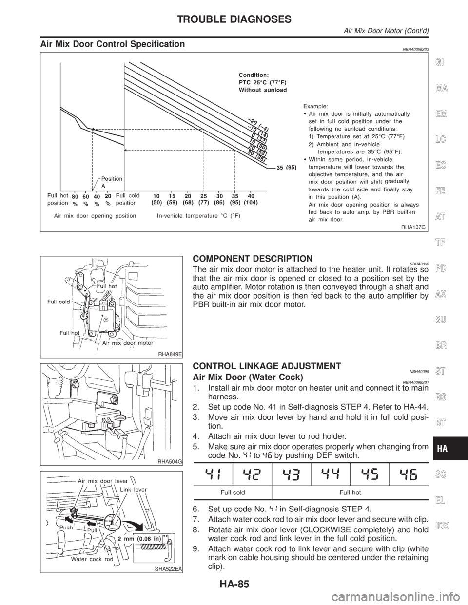
Air Mix Door Control SpecificationNBHA0059S03
RHA137G
RHA849E
COMPONENT DESCRIPTIONNBHA0060The air mix door motor is attached to the heater unit. It rotates so
that the air mix door is opened or closed to a position set by the
auto amplifier. Motor rotation is then conveyed through a shaft and
the air mix door position is then fed back to the auto amplifier by
PBR built-in air mix door motor.
RHA504G
SHA522EA
CONTROL LINKAGE ADJUSTMENTNBHA0099Air Mix Door (Water Cock)NBHA0099S011. Install air mix door motor on heater unit and connect it to main
harness.
2. Set up code No. 41 in Self-diagnosis STEP 4. Refer to HA-44.
3. Move air mix door lever by hand and hold it in full cold posi-
tion.
4. Attach air mix door lever to rod holder.
5. Make sure air mix door operates properly when changing from
code No.
toby pushing DEF switch.
Full cold Full hot
6. Set up code No.in Self-diagnosis STEP 4.
7. Attach water cock rod to air mix door lever and secure with clip.
8. Rotate air mix door lever (CLOCKWISE completely) and hold
water cock rod and link lever in the full cold position.
9. Attach water cock rod to link lever and secure with clip (white
mark on cable housing should be centered under the retaining
clip).
GI
MA
EM
LC
EC
FE
AT
TF
PD
AX
SU
BR
ST
RS
BT
SC
EL
IDX
TROUBLE DIAGNOSES
Air Mix Door Motor (Cont'd)
HA-85
Page 1949 of 2395
Compressor Clutch
OVERHAULNBHA0073
RHA122F
RHA136EB
REMOVALNBHA0074IWhen removing center bolt, hold clutch disc with clutch disc
wrench.
RHA399F
RHA124F
IRemove the clutch disc using the clutch disc puller.
Insert the holder's three pins into the holes in the clutch disc.
Rotate the holder clockwise to hook it onto the plate. Then,
tighten the center bolt to remove the clutch disc.
After removing the clutch disc, remove the shims from either
the drive shaft or the clutch disc.
SERVICE PROCEDURE
Compressor Clutch
HA-150