2001 INFINITI QX4 clock
[x] Cancel search: clockPage 645 of 2395

16 ADJUSTMENT THROTTLE POSITION SWITCH CLOSED POSITION-I
1. Loosen throttle position sensor fixing bolts.
2. Confirm that proper vacuum is applied. Refer to Test No. 10. During adjustment, vacuum should be applied.
3. Insert 0.05 mm (0.0020 in) feeler gauge between stopper and throttle drum as shown in the figure.
SEF953Y
SEF330Z
4. Turn throttle position sensor body counterclockwise until continuity does not exist.
SEF954Y
©GO TO 17.
TROUBLE DIAGNOSIS Ð BASIC INSPECTION
Basic Inspection (Cont'd)
EC-110
Page 646 of 2395

17 ADJUSTMENT THROTTLE POSITION SWITCH CLOSED POSITION-II
1. Temporarily tighten sensor body fixing bolts as follows.
IGradually move the sensor body clockwise and stop it when the continuity comes to exist, then temporarily
tighten sensor body fixing bolts.
SEF954Y
2. Make sure two or three times that the continuity exists when the throttle valve is closed and continuity does not exist
when it is opened.
3. Remove 0.05 mm (0.0020 in) feeler gauge then insert 0.15 mm (0.0059 in) feeler gauge.
4. Make sure two or three times that the continuity does not exist when the throttle valve is closed.
5. Tighten throttle position sensor.
6. Check the continuity again.
Continuity does not exist while closing the throttle valve.
OK or NG
OK©GO TO 18.
NG©GO TO 16.
18 RESET THROTTLE POSITION SENSOR IDLE POSITION MEMORY
NOTE:
Always warm up engine to normal operating temperature. If engine is cool, the throttle position sensor idle posi-
tion memory will not be reset correctly.
1. Confirm that proper vacuum is applied. Refer to Test No. 10.
2. Attach blind cap to vacuum port from which vacuum hose to throttle opener was disconnected.
3. Start engine.
4. Warm up engine to normal operating temperature.
5. Stop engine. (Turn ignition switch ªOFFº.)
6. Turn ignition switch ªONº and wait at least 5 seconds.
SEF864V
7. Turn ignition switch ªOFFº and wait at least 10 seconds.
8. Repeat steps 6 and 7, 20 times.
©GO TO 19.
GI
MA
EM
LC
FE
AT
TF
PD
AX
SU
BR
ST
RS
BT
HA
SC
EL
IDX
TROUBLE DIAGNOSIS Ð BASIC INSPECTION
Basic Inspection (Cont'd)
EC-111
Page 890 of 2395

IIf P0440, P1440 and P1447 are not displayed on the screen,
go to the following step.
10) Select ªMODE 1º with GST.
IIf SRT of EVAP system is set, the result will be OK.
IIf SRT of EVAP system is not set, go to step 6.
Diagnostic ProcedureNBEC0220
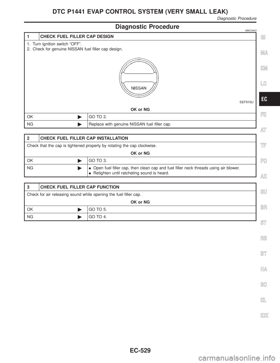
1 CHECK FUEL FILLER CAP DESIGN
1. Turn ignition switch ªOFFº.
2. Check for genuine NISSAN fuel filler cap design.
SEF915U
OK or NG
OK©GO TO 2.
NG©Replace with genuine NISSAN fuel filler cap.
2 CHECK FUEL FILLER CAP INSTALLATION
Check that the cap is tightened properly by rotating the cap clockwise.
OK or NG
OK©GO TO 3.
NG©IOpen fuel filler cap, then clean cap and fuel filler neck threads using air blower.
IRetighten until ratcheting sound is heard.
3 CHECK FUEL FILLER CAP FUNCTION
Check for air releasing sound while opening the fuel filler cap.
OK or NG
OK©GO TO 5.
NG©GO TO 4.
GI
MA
EM
LC
FE
AT
TF
PD
AX
SU
BR
ST
RS
BT
HA
SC
EL
IDX
DTC P0440 EVAP CONTROL SYSTEM (SMALL LEAK) (NEGATIVE PRESSURE)
DTC Confirmation Procedure (Cont'd)
EC-355
Page 932 of 2395

8) Stop vehicle.
9) Select ªMODE 3º with GST.
IIf P0455 is displayed on the screen, go to ªDiagnostic
Procedureº, EC-397.
IIf P0440 or P1440 is displayed on the screen, go to ªDiagnos-
tic Procedureº, for DTC P0440, EC-355.
IIf P1447 is displayed on the screen, go to ªDiagnostic Proce-
dureº for DTC P1447, EC-564.
IIf P0455, P0440, P1440 and P1447 are not displayed on the
screen, go to the following step.
10) Select ªMODE 1º with GST.
IIf SRT of EVAP system is set, the result will be OK.
IIf SRT of EVAP system is not set, go to step 6.
Diagnostic ProcedureNBEC0647
1 CHECK FUEL FILLER CAP DESIGN
1. Turn ignition switch ªOFFº.
2. Check for genuine NISSAN fuel filler cap design.
SEF915U
OK or NG
OK©GO TO 2.
NG©Replace with genuine NISSAN fuel filler cap.
2 CHECK FUEL FILLER CAP INSTALLATION
Check that the cap is tightened properly by rotating the cap clockwise.
OK or NG
OK©GO TO 3.
NG©IOpen fuel filler cap, then clean cap and fuel filler neck threads using air blower.
IRetighten until ratcheting sound is heard.
GI
MA
EM
LC
FE
AT
TF
PD
AX
SU
BR
ST
RS
BT
HA
SC
EL
IDX
DTC P0455 EVAP CONTROL SYSTEM (GROSS LEAK)
DTC Confirmation Procedure (Cont'd)
EC-397
Page 1064 of 2395

Diagnostic ProcedureNBEC0643
1 CHECK FUEL FILLER CAP DESIGN
1. Turn ignition switch ªOFFº.
2. Check for genuine NISSAN fuel filler cap design.
SEF915U
OK or NG
OK©GO TO 2.
NG©Replace with genuine NISSAN fuel filler cap.
2 CHECK FUEL FILLER CAP INSTALLATION
Check that the cap is tightened properly by rotating the cap clockwise.
OK or NG
OK©GO TO 3.
NG©IOpen fuel filler cap, then clean cap and fuel filler neck threads using air blower.
IRetighten until ratcheting sound is heard.
3 CHECK FUEL FILLER CAP FUNCTION
Check for air releasing sound while opening the fuel filler cap.
OK or NG
OK©GO TO 5.
NG©GO TO 4.
GI
MA
EM
LC
FE
AT
TF
PD
AX
SU
BR
ST
RS
BT
HA
SC
EL
IDX
DTC P1441 EVAP CONTROL SYSTEM (VERY SMALL LEAK)
Diagnostic Procedure
EC-529
Page 1187 of 2395

Electrical Components Inspection ...........................108
COMPASS AND THERMOMETER............................. 110
System Description .................................................. 110
Wiring Diagram - COMPAS -................................... 111
Trouble Diagnoses................................................... 112
Calibration Procedure for Compass ........................ 113
WARNING LAMPS...................................................... 114
Schematic ................................................................ 114
Wiring Diagram - WARN - ....................................... 115
Fuel Warning Lamp Sensor Check .........................122
Electrical Components Inspection ...........................122
A/T INDICATOR...........................................................123
Wiring Diagram - AT/IND -.......................................123
WARNING CHIME.......................................................125
Component Parts and Harness Connector
Location ...................................................................125
System Description ..................................................125
Wiring Diagram - CHIME - ......................................127
Trouble Diagnoses...................................................129
FRONT WIPER AND WASHER..................................136
System Description ..................................................136
Wiring Diagram - WIPER - ......................................138
Removal and Installation .........................................139
Washer Nozzle Adjustment .....................................140
Washer Tube Layout ...............................................140
REAR WIPER AND WASHER....................................141
System Description ..................................................141
Wiring Diagram - WIP/R -........................................143
Trouble Diagnoses...................................................145
Removal and Installation .........................................145
Washer Nozzle Adjustment .....................................146
Washer Tube Layout ...............................................146
Check Valve .............................................................146
HORN...........................................................................147
Wiring Diagram - HORN - .......................................147
CIGARETTE LIGHTER................................................148
Wiring Diagram - CIGAR -.......................................148
CLOCK.........................................................................150
Wiring Diagram - CLOCK -......................................150
REAR WINDOW DEFOGGER.....................................151
Component Parts and Harness Connector
Location ...................................................................151
System Description ..................................................151
Wiring Diagram - DEF - ...........................................153
Trouble Diagnoses...................................................155
Electrical Components Inspection ...........................157
Filament Check ........................................................157
Filament Repair .......................................................158
AUDIO..........................................................................160
System Description ..................................................160
Schematic ................................................................161
Wiring Diagram - AUDIO - .......................................162Trouble Diagnoses...................................................166
Inspection.................................................................167
Wiring Diagram - REMOTE -...................................168
AUDIO ANTENNA.......................................................169
System Description ..................................................169
Wiring Diagram - P/ANT - .......................................170
Trouble Diagnoses...................................................171
Location of Antenna .................................................171
Antenna Rod Replacement .....................................171
POWER SUNROOF.....................................................173
System Description ..................................................173
Wiring Diagram - SROOF - .....................................174
Trouble Diagnoses...................................................176
DOOR MIRROR...........................................................177
Wiring Diagram - MIRROR - ...................................177
GLASS HATCH OPENER...........................................178
System Description ..................................................178
Wiring Diagram - TLID - ..........................................179
FUEL FILLER LID OPENER.......................................180
Wiring Diagram - F/LID - .........................................180
POWER SEAT.............................................................181
Wiring Diagram - SEAT - .........................................181
HEATED SEAT............................................................183
Wiring Diagram - HSEAT - ......................................183
Seatback Heating Unit .............................................185
AUTOMATIC DRIVE POSITIONER............................186
Component Parts and Harness Connector
Location ...................................................................186
System Description ..................................................187
Schematic ................................................................190
Wiring Diagram - AUT/DP - .....................................191
On Board Diagnosis ................................................196
Trouble Diagnoses...................................................198
AUTOMATIC SPEED CONTROL DEVICE (ASCD)...221
Component Parts and Harness Connector
Location ...................................................................221
System Description ..................................................222
Schematic ................................................................224
Wiring Diagram - ASCD - ........................................225
Fail-safe System ......................................................229
Trouble Diagnoses...................................................230
Electrical Component Inspection .............................239
ASCD Wire Adjustment ...........................................240
POWER WINDOW.......................................................241
System Description ..................................................241
Schematic ................................................................244
Wiring Diagram - WINDOW - ..................................245
Trouble Diagnoses...................................................250
POWER DOOR LOCK.................................................254
Component Parts and Harness Connector
Location ...................................................................254
System Description ..................................................254
CONTENTS(Cont'd)
EL-2
Page 1229 of 2395

SEL461X
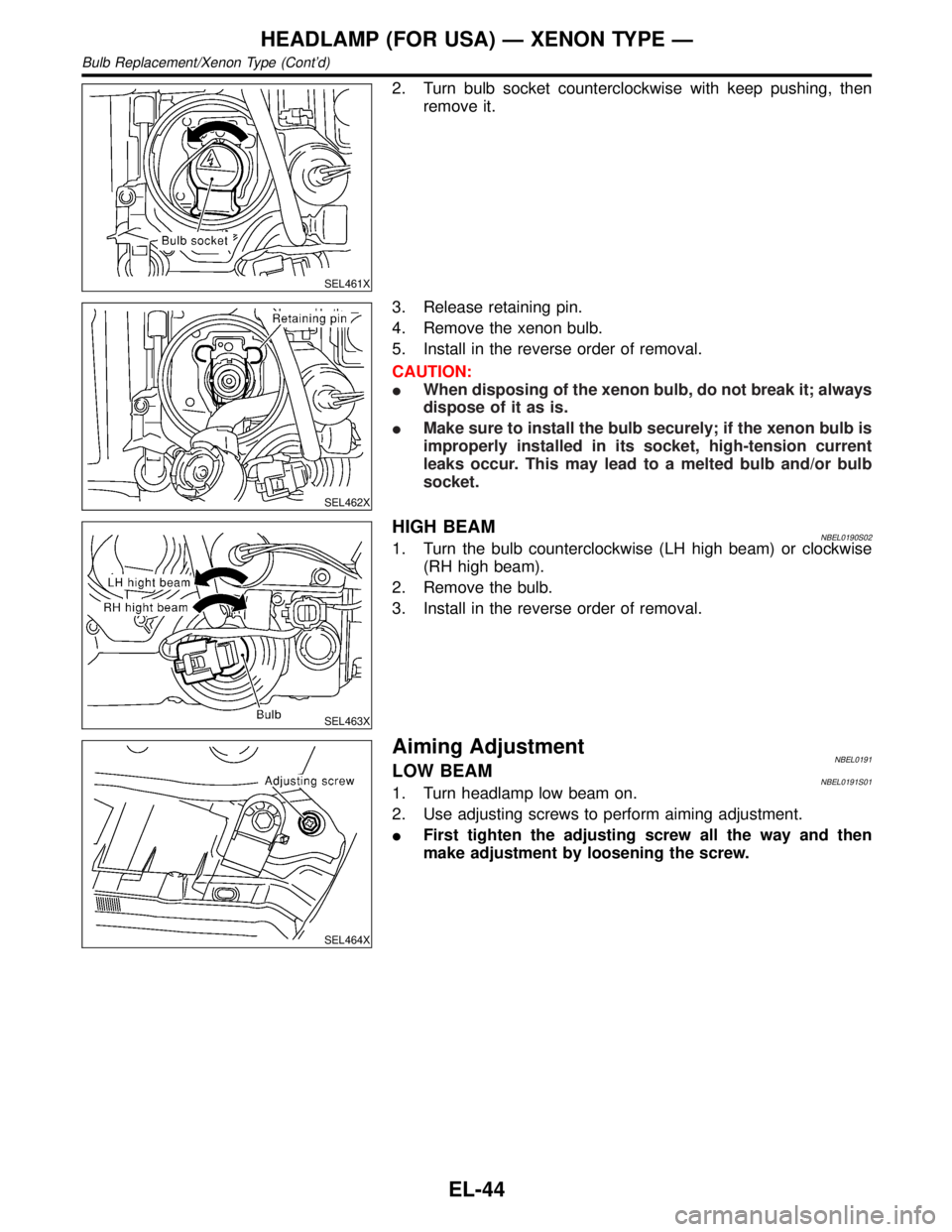
2. Turn bulb socket counterclockwise with keep pushing, then
remove it.
SEL462X
3. Release retaining pin.
4. Remove the xenon bulb.
5. Install in the reverse order of removal.
CAUTION:
IWhen disposing of the xenon bulb, do not break it; always
dispose of it as is.
IMake sure to install the bulb securely; if the xenon bulb is
improperly installed in its socket, high-tension current
leaks occur. This may lead to a melted bulb and/or bulb
socket.
SEL463X
HIGH BEAMNBEL0190S021. Turn the bulb counterclockwise (LH high beam) or clockwise
(RH high beam).
2. Remove the bulb.
3. Install in the reverse order of removal.
SEL464X
Aiming AdjustmentNBEL0191LOW BEAMNBEL0191S011. Turn headlamp low beam on.
2. Use adjusting screws to perform aiming adjustment.
IFirst tighten the adjusting screw all the way and then
make adjustment by loosening the screw.
HEADLAMP (FOR USA) Ð XENON TYPE Ð
Bulb Replacement/Xenon Type (Cont'd)
EL-44
Page 1266 of 2395

Component Connector No. Power terminal Ground terminal
IVCS switch R10 2 12
Display & NAVI control unit M117, M118 8 24
A/C auto amp. M102 24 25
Clock M39 3 4
Globe box lamp M30 1 2
The ground for all of the components except for compass, glove box lamp and ashtray are controlled through
terminals 2 and 3 of the illumination control switch and body grounds M77 and M111.
BATTERY SAVER CONTROLNBEL0035S02When the ignition switch is turned from ON (or START) to OFF (or ACC) positions while illumination lamps
are illuminated, the RAP signal is supplied to terminal 10 of the headlamp battery saver control unit from smart
entrance control unit terminal 5.
After counting 45 seconds by the RAP signal from the smart entrance control unit to headlamp battery saver
control unit, the ground supply to terminal 1 of the tail lamp relay from headlamp battery saver control unit
teminals 6 and 14 is terminated.
Then illumination lamps are turned off.
Illumination lamps are turned off when driver or passenger side door is opened even if 45 seconds have not
passed after the ignition switch is turned from ON (or START) to OFF (or ACC) positions while illumination
lamps are illuminated.
When the lighting switch is turned from OFF to 1ST (or 2ND) after illumination lamps are turned off by the
battery saver control, ground is supplied
Ito headlamp battery saver control unit terminals 5 and 13 from lighting switch terminal 11, and
Ito tail lamp relay terminal 1 from headlamp battery saver control unit terminals 6 and 14.
Then illumination lamps illuminate again.
NOTE:
For Trouble Diagnoses for battery saver control, refer to ªPARKING, LICENSE AND TAIL LAMPSº
(EL-66).
GI
MA
EM
LC
EC
FE
AT
TF
PD
AX
SU
BR
ST
RS
BT
HA
SC
IDX
ILLUMINATION
System Description (Cont'd)
EL-81