2001 INFINITI QX4 clock
[x] Cancel search: clockPage 1335 of 2395
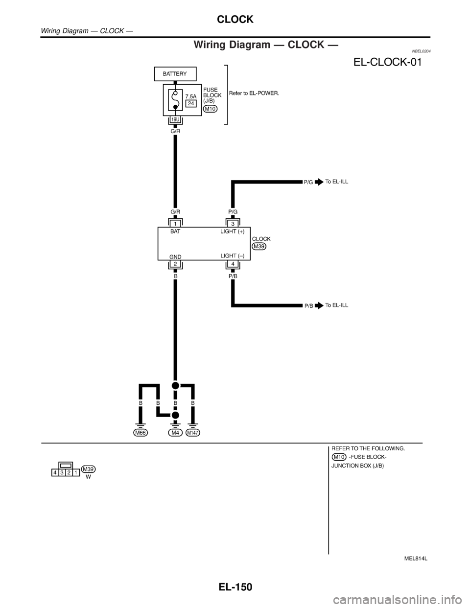
Wiring Diagram Ð CLOCK ÐNBEL0204
MEL814L
CLOCK
Wiring Diagram Ð CLOCK Ð
EL-150
Page 1587 of 2395
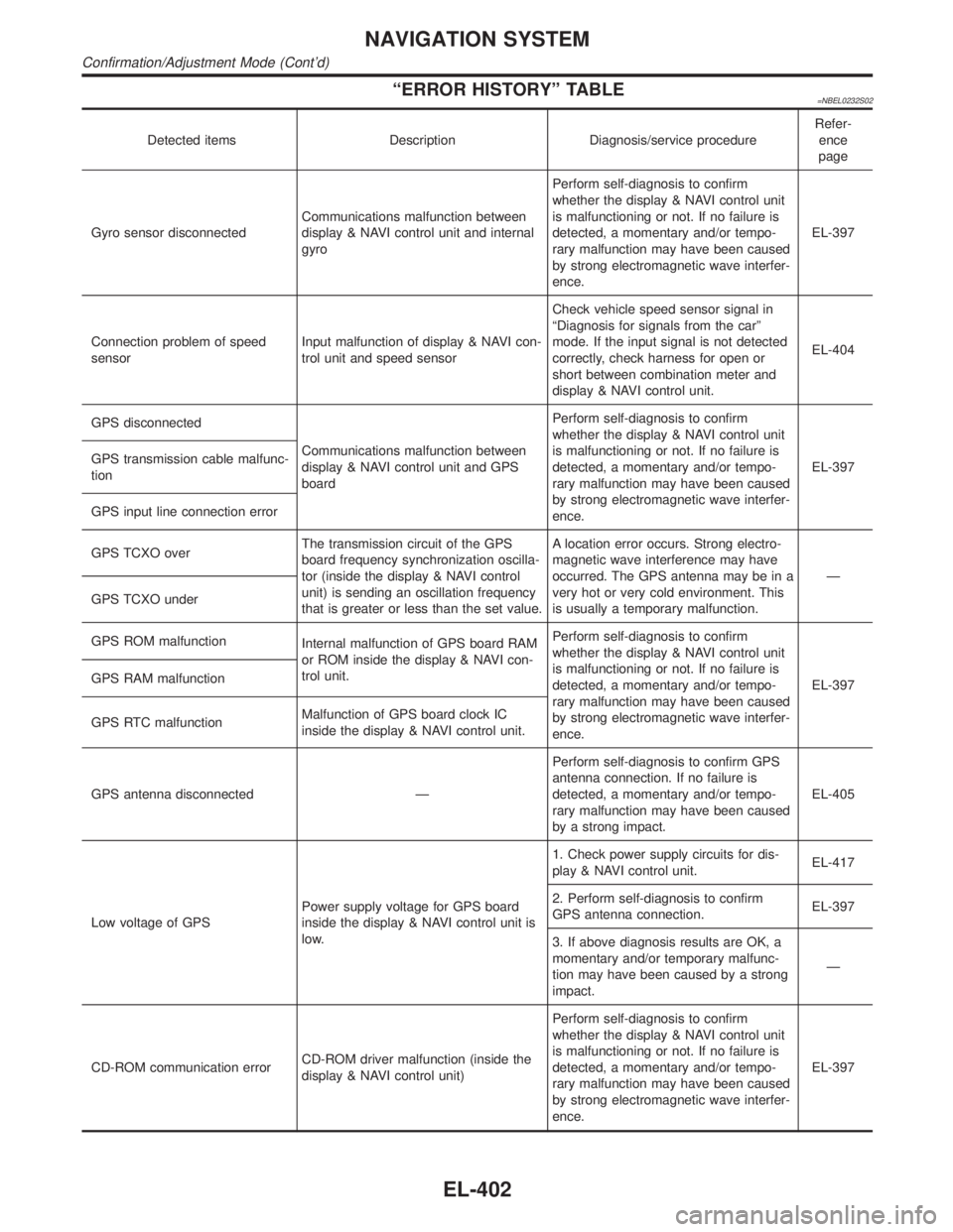
ªERROR HISTORYº TABLE=NBEL0232S02
Detected items Description Diagnosis/service procedureRefer-
ence
page
Gyro sensor disconnectedCommunications malfunction between
display & NAVI control unit and internal
gyroPerform self-diagnosis to confirm
whether the display & NAVI control unit
is malfunctioning or not. If no failure is
detected, a momentary and/or tempo-
rary malfunction may have been caused
by strong electromagnetic wave interfer-
ence.EL-397
Connection problem of speed
sensorInput malfunction of display & NAVI con-
trol unit and speed sensorCheck vehicle speed sensor signal in
ªDiagnosis for signals from the carº
mode. If the input signal is not detected
correctly, check harness for open or
short between combination meter and
display & NAVI control unit.EL-404
GPS disconnected
Communications malfunction between
display & NAVI control unit and GPS
boardPerform self-diagnosis to confirm
whether the display & NAVI control unit
is malfunctioning or not. If no failure is
detected, a momentary and/or tempo-
rary malfunction may have been caused
by strong electromagnetic wave interfer-
ence.EL-397 GPS transmission cable malfunc-
tion
GPS input line connection error
GPS TCXO overThe transmission circuit of the GPS
board frequency synchronization oscilla-
tor (inside the display & NAVI control
unit) is sending an oscillation frequency
that is greater or less than the set value.A location error occurs. Strong electro-
magnetic wave interference may have
occurred. The GPS antenna may be in a
very hot or very cold environment. This
is usually a temporary malfunction.Ð
GPS TCXO under
GPS ROM malfunction
Internal malfunction of GPS board RAM
or ROM inside the display & NAVI con-
trol unit.Perform self-diagnosis to confirm
whether the display & NAVI control unit
is malfunctioning or not. If no failure is
detected, a momentary and/or tempo-
rary malfunction may have been caused
by strong electromagnetic wave interfer-
ence.EL-397 GPS RAM malfunction
GPS RTC malfunctionMalfunction of GPS board clock IC
inside the display & NAVI control unit.
GPS antenna disconnected ÐPerform self-diagnosis to confirm GPS
antenna connection. If no failure is
detected, a momentary and/or tempo-
rary malfunction may have been caused
by a strong impact.EL-405
Low voltage of GPSPower supply voltage for GPS board
inside the display & NAVI control unit is
low.1. Check power supply circuits for dis-
play & NAVI control unit.EL-417
2. Perform self-diagnosis to confirm
GPS antenna connection.EL-397
3. If above diagnosis results are OK, a
momentary and/or temporary malfunc-
tion may have been caused by a strong
impact.Ð
CD-ROM communication errorCD-ROM driver malfunction (inside the
display & NAVI control unit)Perform self-diagnosis to confirm
whether the display & NAVI control unit
is malfunctioning or not. If no failure is
detected, a momentary and/or tempo-
rary malfunction may have been caused
by strong electromagnetic wave interfer-
ence.EL-397
NAVIGATION SYSTEM
Confirmation/Adjustment Mode (Cont'd)
EL-402
Page 1642 of 2395
NBEL0145
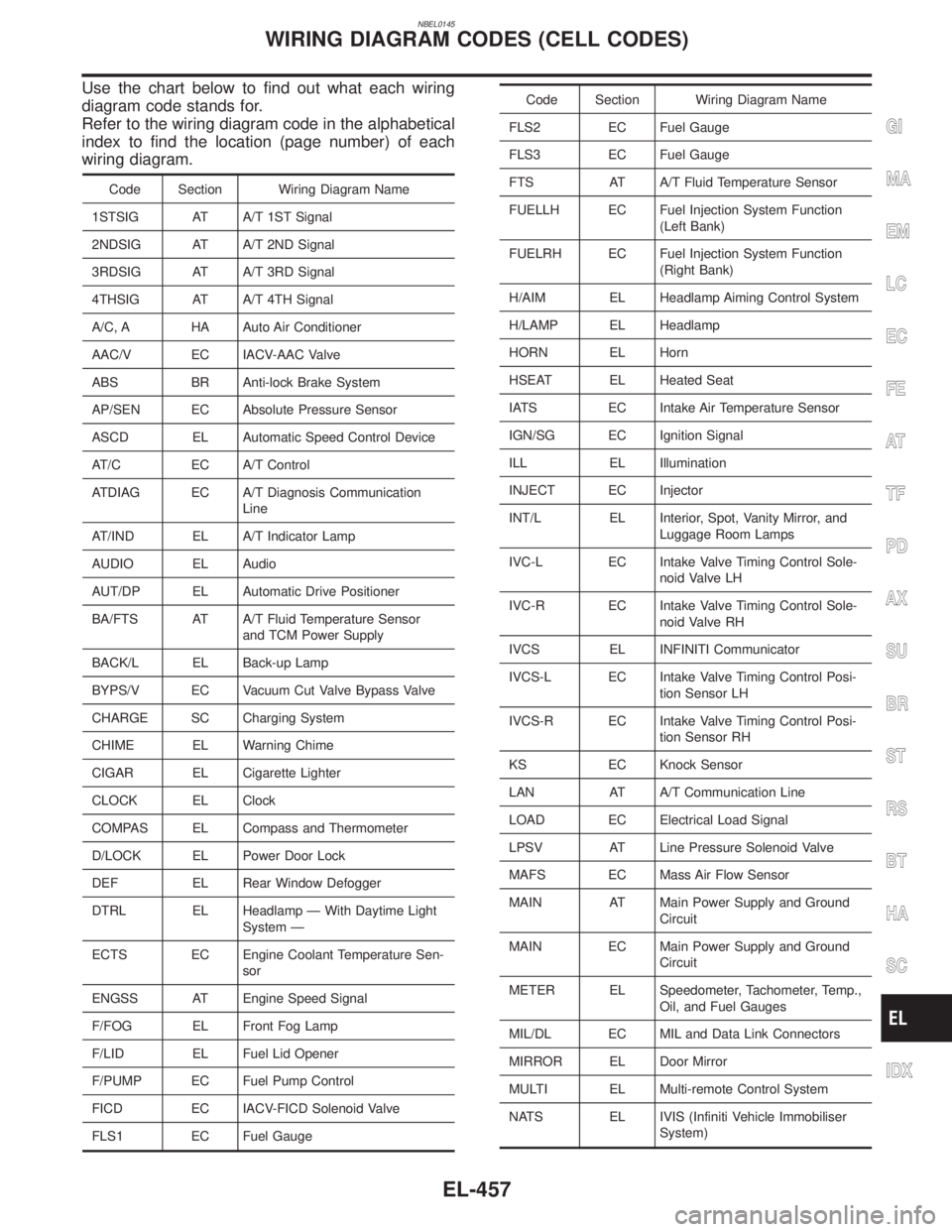
Use the chart below to find out what each wiring
diagram code stands for.
Refer to the wiring diagram code in the alphabetical
index to find the location (page number) of each
wiring diagram.
Code Section Wiring Diagram Name
1STSIG AT A/T 1ST Signal
2NDSIG AT A/T 2ND Signal
3RDSIG AT A/T 3RD Signal
4THSIG AT A/T 4TH Signal
A/C, A HA Auto Air Conditioner
AAC/V EC IACV-AAC Valve
ABS BR Anti-lock Brake System
AP/SEN EC Absolute Pressure Sensor
ASCD EL Automatic Speed Control Device
AT/C EC A/T Control
ATDIAG EC A/T Diagnosis Communication
Line
AT/IND EL A/T Indicator Lamp
AUDIO EL Audio
AUT/DP EL Automatic Drive Positioner
BA/FTS AT A/T Fluid Temperature Sensor
and TCM Power Supply
BACK/L EL Back-up Lamp
BYPS/V EC Vacuum Cut Valve Bypass Valve
CHARGE SC Charging System
CHIME EL Warning Chime
CIGAR EL Cigarette Lighter
CLOCK EL Clock
COMPAS EL Compass and Thermometer
D/LOCK EL Power Door Lock
DEF EL Rear Window Defogger
DTRL EL Headlamp Ð With Daytime Light
System Ð
ECTS EC Engine Coolant Temperature Sen-
sor
ENGSS AT Engine Speed Signal
F/FOG EL Front Fog Lamp
F/LID EL Fuel Lid Opener
F/PUMP EC Fuel Pump Control
FICD EC IACV-FICD Solenoid Valve
FLS1 EC Fuel Gauge
Code Section Wiring Diagram Name
FLS2 EC Fuel Gauge
FLS3 EC Fuel Gauge
FTS AT A/T Fluid Temperature Sensor
FUELLH EC Fuel Injection System Function
(Left Bank)
FUELRH EC Fuel Injection System Function
(Right Bank)
H/AIM EL Headlamp Aiming Control System
H/LAMP EL Headlamp
HORN EL Horn
HSEAT EL Heated Seat
IATS EC Intake Air Temperature Sensor
IGN/SG EC Ignition Signal
ILL EL Illumination
INJECT EC Injector
INT/L EL Interior, Spot, Vanity Mirror, and
Luggage Room Lamps
IVC-L EC Intake Valve Timing Control Sole-
noid Valve LH
IVC-R EC Intake Valve Timing Control Sole-
noid Valve RH
IVCS EL INFINITI Communicator
IVCS-L EC Intake Valve Timing Control Posi-
tion Sensor LH
IVCS-R EC Intake Valve Timing Control Posi-
tion Sensor RH
KS EC Knock Sensor
LAN AT A/T Communication Line
LOAD EC Electrical Load Signal
LPSV AT Line Pressure Solenoid Valve
MAFS EC Mass Air Flow Sensor
MAIN AT Main Power Supply and Ground
Circuit
MAIN EC Main Power Supply and Ground
Circuit
METER EL Speedometer, Tachometer, Temp.,
Oil, and Fuel Gauges
MIL/DL EC MIL and Data Link Connectors
MIRROR EL Door Mirror
MULTI EL Multi-remote Control System
NATS EL IVIS (Infiniti Vehicle Immobiliser
System)
GI
MA
EM
LC
EC
FE
AT
TF
PD
AX
SU
BR
ST
RS
BT
HA
SC
IDX
WIRING DIAGRAM CODES (CELL CODES)
EL-457
Page 1692 of 2395
SEM877EA
SEM878EA
SEM879EA
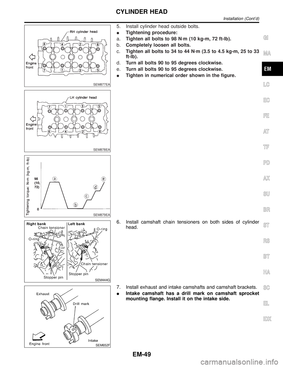
5. Install cylinder head outside bolts.
ITightening procedure:
a.Tighten all bolts to 98 N´m (10 kg-m, 72 ft-lb).
b.Completely loosen all bolts.
c.Tighten all bolts to 34 to 44 N´m (3.5 to 4.5 kg-m, 25 to 33
ft-lb).
d.Turn all bolts 90 to 95 degrees clockwise.
e.Turn all bolts 90 to 95 degrees clockwise.
ITighten in numerical order shown in the figure.
SEM444G
6. Install camshaft chain tensioners on both sides of cylinder
head.
SEM652F
7. Install exhaust and intake camshafts and camshaft brackets.
IIntake camshaft has a drill mark on camshaft sprocket
mounting flange. Install it on the intake side.
GI
MA
LC
EC
FE
AT
TF
PD
AX
SU
BR
ST
RS
BT
HA
SC
EL
IDX
CYLINDER HEAD
Installation (Cont'd)
EM-49
Page 1693 of 2395
SEM653F
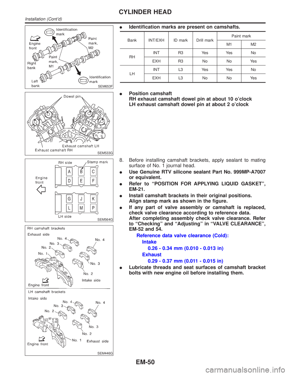
IIdentification marks are present on camshafts.
Bank INT/EXH ID mark Drill markPaint mark
M1 M2
RHINT R3 Yes Yes No
EXH R3 No No Yes
LHINT L3 Yes Yes No
EXH L3 No No Yes
SEM533G
IPosition camshaft
RH exhaust camshaft dowel pin at about 10 o'clock
LH exhaust camshaft dowel pin at about 2 o'clock
SEM564G
SEM446G
8. Before installing camshaft brackets, apply sealant to mating
surface of No. 1 journal head.
IUse Genuine RTV silicone sealant Part No. 999MP-A7007
or equivalent.
IRefer to ªPOSITION FOR APPLYING LIQUID GASKETº,
EM-21.
IInstall camshaft brackets in their original positions.
Align stamp mark as shown in the figure.
IIf any part of valve assembly or camshaft is replaced,
check valve clearance according to reference data.
After completing assembly check valve clearance. Refer
to ªCheckingº and ªAdjustingº in ªVALVE CLEARANCEº,
EM-52 and 54.
Reference data valve clearance (Cold):
Intake
0.26 - 0.34 mm (0.010 - 0.013 in)
Exhaust
0.29 - 0.37 mm (0.011 - 0.015 in)
ILubricate threads and seat surfaces of camshaft bracket
bolts with new engine oil before installing them.
CYLINDER HEAD
Installation (Cont'd)
EM-50
Page 1715 of 2395
SEM177F
SEM456G
2. Instructions for re-use of main bearing cap bolts.
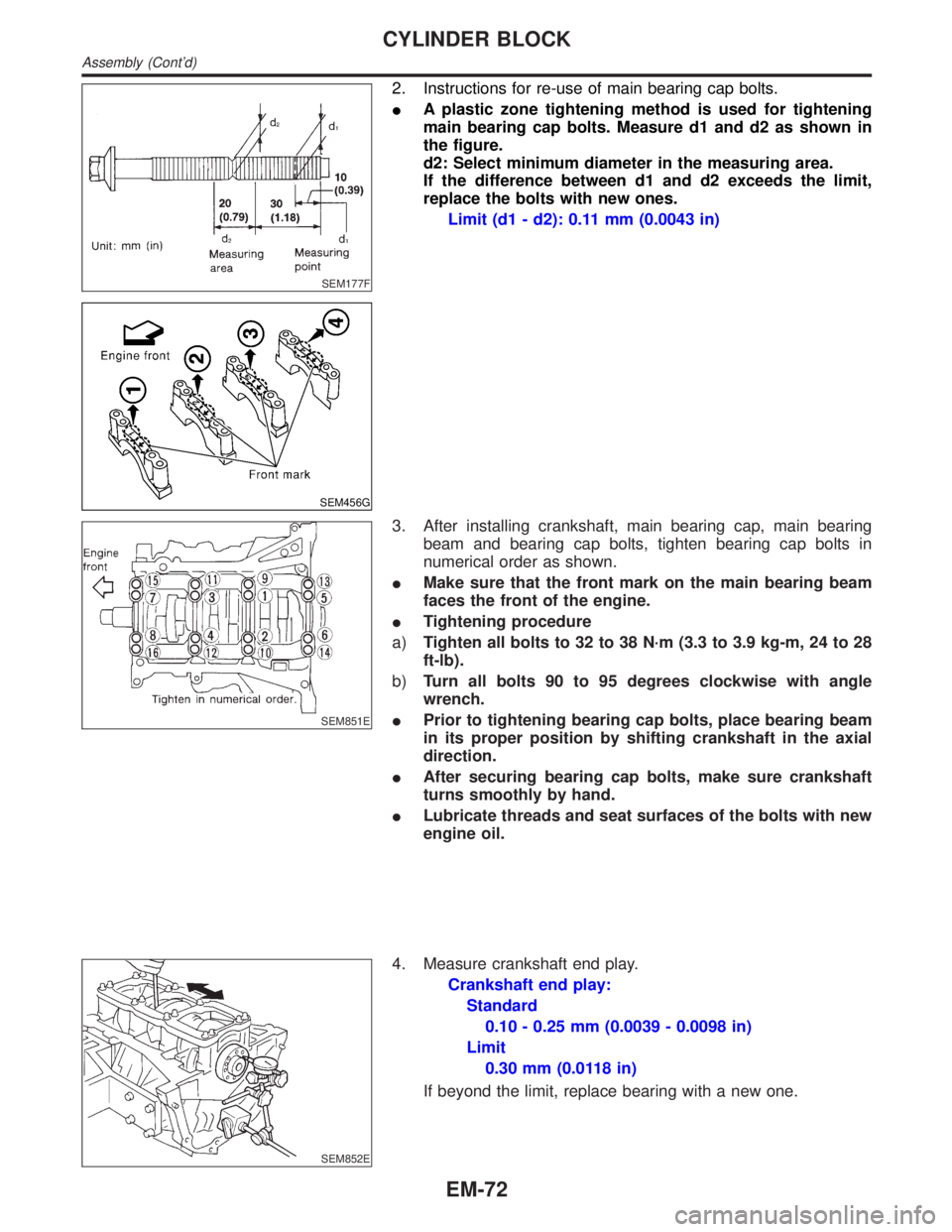
IA plastic zone tightening method is used for tightening
main bearing cap bolts. Measure d1 and d2 as shown in
the figure.
d2: Select minimum diameter in the measuring area.
If the difference between d1 and d2 exceeds the limit,
replace the bolts with new ones.
Limit (d1 - d2): 0.11 mm (0.0043 in)
SEM851E
3. After installing crankshaft, main bearing cap, main bearing
beam and bearing cap bolts, tighten bearing cap bolts in
numerical order as shown.
IMake sure that the front mark on the main bearing beam
faces the front of the engine.
ITightening procedure
a)Tighten all bolts to 32 to 38 N´m (3.3 to 3.9 kg-m, 24 to 28
ft-lb).
b)Turn all bolts 90 to 95 degrees clockwise with angle
wrench.
IPrior to tightening bearing cap bolts, place bearing beam
in its proper position by shifting crankshaft in the axial
direction.
IAfter securing bearing cap bolts, make sure crankshaft
turns smoothly by hand.
ILubricate threads and seat surfaces of the bolts with new
engine oil.
SEM852E
4. Measure crankshaft end play.
Crankshaft end play:
Standard
0.10 - 0.25 mm (0.0039 - 0.0098 in)
Limit
0.30 mm (0.0118 in)
If beyond the limit, replace bearing with a new one.
CYLINDER BLOCK
Assembly (Cont'd)
EM-72
Page 1716 of 2395
SEM455G
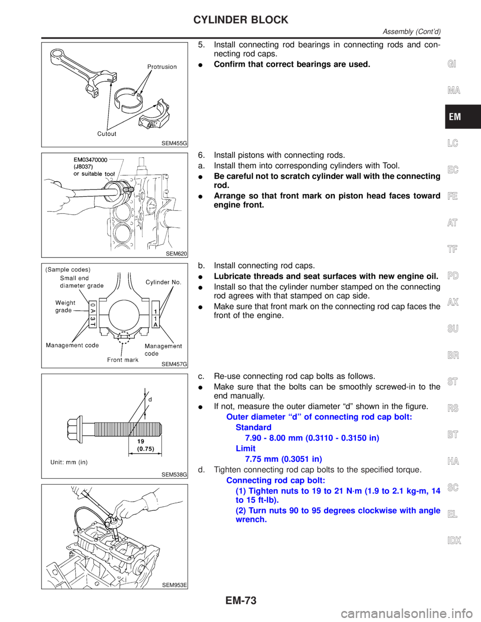
5. Install connecting rod bearings in connecting rods and con-
necting rod caps.
IConfirm that correct bearings are used.
SEM620
6. Install pistons with connecting rods.
a. Install them into corresponding cylinders with Tool.
IBe careful not to scratch cylinder wall with the connecting
rod.
IArrange so that front mark on piston head faces toward
engine front.
SEM457G
b. Install connecting rod caps.
ILubricate threads and seat surfaces with new engine oil.
IInstall so that the cylinder number stamped on the connecting
rod agrees with that stamped on cap side.
IMake sure that front mark on the connecting rod cap faces the
front of the engine.
SEM538G
SEM953E
c. Re-use connecting rod cap bolts as follows.
IMake sure that the bolts can be smoothly screwed-in to the
end manually.
IIf not, measure the outer diameter ªdº shown in the figure.
Outer diameter ªdº of connecting rod cap bolt:
Standard
7.90 - 8.00 mm (0.3110 - 0.3150 in)
Limit
7.75 mm (0.3051 in)
d. Tighten connecting rod cap bolts to the specified torque.
Connecting rod cap bolt:
(1) Tighten nuts to 19 to 21 N´m (1.9 to 2.1 kg-m, 14
to 15 ft-lb).
(2) Turn nuts 90 to 95 degrees clockwise with angle
wrench.
GI
MA
LC
EC
FE
AT
TF
PD
AX
SU
BR
ST
RS
BT
HA
SC
EL
IDX
CYLINDER BLOCK
Assembly (Cont'd)
EM-73
Page 1807 of 2395
RHA273D
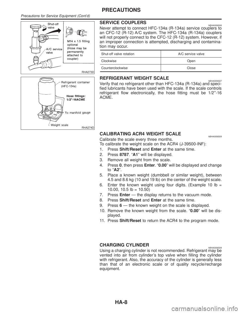
SERVICE COUPLERSNBHA0006S06Never attempt to connect HFC-134a (R-134a) service couplers to
an CFC-12 (R-12) A/C system. The HFC-134a (R-134a) couplers
will not properly connect to the CFC-12 (R-12) system. However, if
an improper connection is attempted, discharging and contamina-
tion may occur.
Shut-off valve rotation A/C service valve
Clockwise Open
Counterclockwise Close
RHA274D
REFRIGERANT WEIGHT SCALENBHA0006S07Verify that no refrigerant other than HFC-134a (R-134a) and speci-
fied lubricants have been used with the scale. If the scale controls
refrigerant flow electronically, the hose fitting must be 1/2²-16
ACME.
CALIBRATING ACR4 WEIGHT SCALENBHA0006S09Calibrate the scale every three months.
To calibrate the weight scale on the ACR4 (J-39500-INF):
1. PressShift/ResetandEnterat the same time.
2. Press8787.ªA1º will be displayed.
3. Remove all weight from the scale.
4. Press0, then pressEnter.ª0.00º will be displayed and change
to ªA2º.
5. Place a known weight (dumbbell or similar weight), between
4.5 and 8.6 kg (10 and 19 lb) on the center of the weight scale.
6. Enter the known weight using four digits. (Example 10 lb =
10.00, 10.5 lb = 10.50)
7. PressEnterÐ the display returns to the vacuum mode.
8. PressShift/ResetandEnterat the same time.
9. Press6Ð the known weight on the scale is displayed.
10. Remove the known weight from the scale. ª0.00º will be dis-
played.
11. PressShift/Resetto return the ACR4 to the program mode.
CHARGING CYLINDERNBHA0006S08Using a charging cylinder is not recommended. Refrigerant may be
vented into air from cylinder's top valve when filling the cylinder
with refrigerant. Also, the accuracy of the cylinder is generally less
than that of an electronic scale or of quality recycle/recharge
equipment.
PRECAUTIONS
Precautions for Service Equipment (Cont'd)
HA-8