Page 1067 of 2395
6 CHECK FOR EVAP LEAK
With CONSULT-II
1. Turn ignition switch ªONº.
2. Select ªEVAP SYSTEM CLOSEº of ªWORK SUPPORTº mode with CONSULT-II.
3. Touch ªSTARTº and apply pressure into the EVAP line until the pressure indicator reaches the middle of the bar graph.
NOTE:
INever use compressed air or a high pressure pump.
IDo not exceed 4.12 kPa (0.042 kg/cm
2, 0.6 psi) of pressure in the system.
PEF917U
4. Using EVAP leak detector, locate the EVAP leak. For the leak detector, refer to the instruction manual for more details.
Refer to ªEVAPORATIVE EMISSION LINE DRAWINGº, EC-36.
SEF200U
OK or NG
OK©GO TO 8.
NG©Repair or replace.
DTC P1441 EVAP CONTROL SYSTEM (VERY SMALL LEAK)
Diagnostic Procedure (Cont'd)
EC-532
Page 1068 of 2395

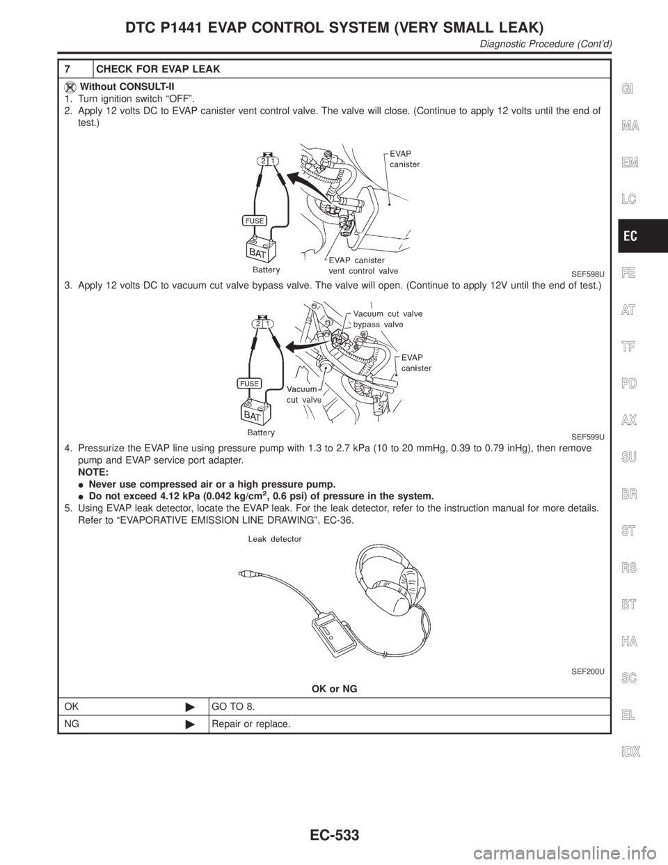
7 CHECK FOR EVAP LEAK
Without CONSULT-II
1. Turn ignition switch ªOFFº.
2. Apply 12 volts DC to EVAP canister vent control valve. The valve will close. (Continue to apply 12 volts until the end of
test.)
SEF598U
3. Apply 12 volts DC to vacuum cut valve bypass valve. The valve will open. (Continue to apply 12V until the end of test.)
SEF599U
4. Pressurize the EVAP line using pressure pump with 1.3 to 2.7 kPa (10 to 20 mmHg, 0.39 to 0.79 inHg), then remove
pump and EVAP service port adapter.
NOTE:
INever use compressed air or a high pressure pump.
IDo not exceed 4.12 kPa (0.042 kg/cm
2, 0.6 psi) of pressure in the system.
5. Using EVAP leak detector, locate the EVAP leak. For the leak detector, refer to the instruction manual for more details.
Refer to ªEVAPORATIVE EMISSION LINE DRAWINGº, EC-36.
SEF200U
OK or NG
OK©GO TO 8.
NG©Repair or replace.
GI
MA
EM
LC
FE
AT
TF
PD
AX
SU
BR
ST
RS
BT
HA
SC
EL
IDX
DTC P1441 EVAP CONTROL SYSTEM (VERY SMALL LEAK)
Diagnostic Procedure (Cont'd)
EC-533
Page 1069 of 2395

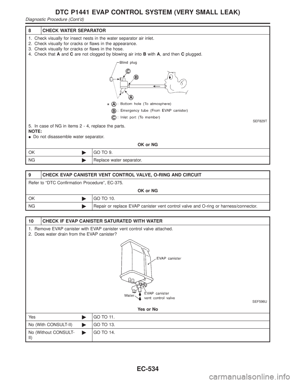
8 CHECK WATER SEPARATOR
1. Check visually for insect nests in the water separator air inlet.
2. Check visually for cracks or flaws in the appearance.
3. Check visually for cracks or flaws in the hose.
4. Check thatAandCare not clogged by blowing air intoBwithA, and thenCplugged.
SEF829T
5. In case of NG in items2-4,replace the parts.
NOTE:
IDo not disassemble water separator.
OK or NG
OK©GO TO 9.
NG©Replace water separator.
9 CHECK EVAP CANISTER VENT CONTROL VALVE, O-RING AND CIRCUIT
Refer to ªDTC Confirmation Procedureº, EC-375.
OK or NG
OK©GO TO 10.
NG©Repair or replace EVAP canister vent control valve and O-ring or harness/connector.
10 CHECK IF EVAP CANISTER SATURATED WITH WATER
1. Remove EVAP canister with EVAP canister vent control valve attached.
2. Does water drain from the EVAP canister?
SEF596U
YesorNo
Ye s©GO TO 11.
No (With CONSULT-II)©GO TO 13.
No (Without CONSULT-
II)©GO TO 14.
DTC P1441 EVAP CONTROL SYSTEM (VERY SMALL LEAK)
Diagnostic Procedure (Cont'd)
EC-534
Page 1070 of 2395

11 CHECK EVAP CANISTER
Weigh the EVAP canister with the EVAP canister vent control valve attached.
The weight should be less than 1.8 kg (4.0 lb).
OK or NG
OK (With CONSULT-II)©GO TO 13.
OK (Without CONSULT-
II)©GO TO 14.
NG©GO TO 12.
12 DETECT MALFUNCTIONING PART
Check the following.
IEVAP canister for damage
IEVAP hose between EVAP canister and water separator for clogging or poor connection
©Repair hose or replace EVAP canister.
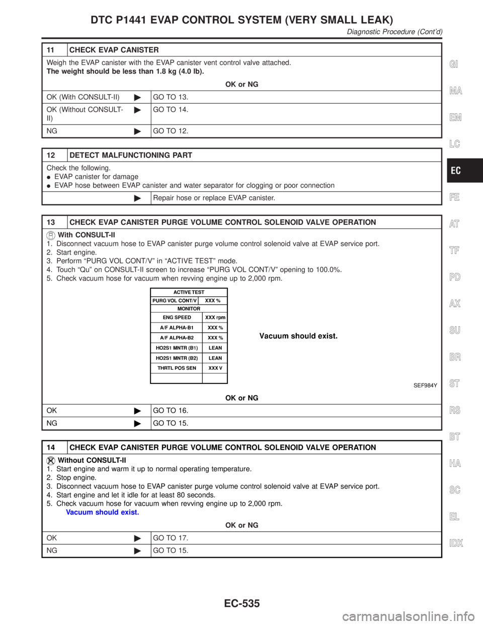
13 CHECK EVAP CANISTER PURGE VOLUME CONTROL SOLENOID VALVE OPERATION
With CONSULT-II
1. Disconnect vacuum hose to EVAP canister purge volume control solenoid valve at EVAP service port.
2. Start engine.
3. Perform ªPURG VOL CONT/Vº in ªACTIVE TESTº mode.
4. Touch ªQuº on CONSULT-II screen to increase ªPURG VOL CONT/Vº opening to 100.0%.
5. Check vacuum hose for vacuum when revving engine up to 2,000 rpm.
SEF984Y
OK or NG
OK©GO TO 16.
NG©GO TO 15.
14 CHECK EVAP CANISTER PURGE VOLUME CONTROL SOLENOID VALVE OPERATION
Without CONSULT-II
1. Start engine and warm it up to normal operating temperature.
2. Stop engine.
3. Disconnect vacuum hose to EVAP canister purge volume control solenoid valve at EVAP service port.
4. Start engine and let it idle for at least 80 seconds.
5. Check vacuum hose for vacuum when revving engine up to 2,000 rpm.
Vacuum should exist.
OK or NG
OK©GO TO 17.
NG©GO TO 15.
GI
MA
EM
LC
FE
AT
TF
PD
AX
SU
BR
ST
RS
BT
HA
SC
EL
IDX
DTC P1441 EVAP CONTROL SYSTEM (VERY SMALL LEAK)
Diagnostic Procedure (Cont'd)
EC-535
Page 1071 of 2395
15 CHECK VACUUM HOSE
Check vacuum hoses for clogging or disconnection. Refer to ªVacuum Hose Drawingº, EC-26.
OK or NG
OK (With CONSULT-II)©GO TO 16.
OK (Without CONSULT-
II)©GO TO 17.
NG©Repair or reconnect the hose.
16 CHECK EVAP CANISTER PURGE VOLUME CONTROL SOLENOID VALVE
With CONSULT-II
1. Start engine.
2. Perform ªPURG VOL CONT/Vº in ªACTIVE TESTº mode with CONSULT-II. Check that engine speed varies according
to the valve opening.
SEF985Y
OK or NG
OK©GO TO 18.
NG©GO TO 17.
DTC P1441 EVAP CONTROL SYSTEM (VERY SMALL LEAK)
Diagnostic Procedure (Cont'd)
EC-536
Page 1072 of 2395
17 CHECK EVAP CANISTER PURGE VOLUME CONTROL SOLENOID VALVE
With CONSULT-II
Check air passage continuity of EVAP canister purge volume control solenoid valve under the following conditions.
SEF986Y
SEF334X
Without CONSULT-II
Check air passage continuity of EVAP canister purge volume control solenoid valve under the following conditions.
SEF986Y
SEF335X
OK or NG
OK©GO TO 18.
NG©Replace EVAP canister purge volume control solenoid valve.
GI
MA
EM
LC
FE
AT
TF
PD
AX
SU
BR
ST
RS
BT
HA
SC
EL
IDX
DTC P1441 EVAP CONTROL SYSTEM (VERY SMALL LEAK)
Diagnostic Procedure (Cont'd)
EC-537
Page 1073 of 2395
18 CHECK ABSOLUTE PRESSURE SENSOR
1. Remove absolute pressure sensor with its harness connector connected.
SEF961Y
2. Remove hose from absolute pressure sensor.
3. Install a vacuum pump to absolute pressure sensor.
4. Turn ignition switch ªONº and check output voltage between ECM terminal 80 and engine ground under the following
conditions.
SEF300XA
CAUTION:
IAlways calibrate the vacuum pump gauge when using it.
IDo not apply below þ93.3 kPa (±700 mmHg, ±27.56 inHg) or over 101.3 kPa (760 mmHg, 29.92 inHg) of pressure.
OK or NG
OK©GO TO 19.
NG©Replace absolute pressure sensor.
19 CHECK FUEL TANK TEMPERATURE SENSOR
1. Remove fuel level sensor unit.
2. Check resistance between fuel level sensor unit and fuel pump terminals 1 and 2 by heating with hot water or heat gun
as shown in the figure.
SEF974Y
OK or NG
OK©GO TO 20.
NG©Replace fuel level sensor unit.
DTC P1441 EVAP CONTROL SYSTEM (VERY SMALL LEAK)
Diagnostic Procedure (Cont'd)
EC-538
Page 1074 of 2395

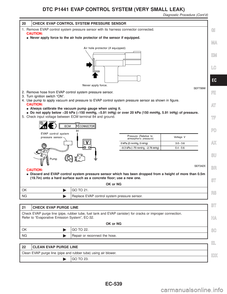
20 CHECK EVAP CONTROL SYSTEM PRESSURE SENSOR
1. Remove EVAP control system pressure sensor with its harness connector connected.
CAUTION:
INever apply force to the air hole protector of the sensor if equipped.
SEF799W
2. Remove hose from EVAP control system pressure sensor.
3. Turn ignition switch ªONº.
4. Use pump to apply vacuum and pressure to EVAP control system pressure sensor as shown in figure.
CAUTION:
IAlways calibrate the vacuum pump gauge when using it.
IDo not apply below þ20 kPa (þ150 mmHg, þ5.91 inHg) or over 20 kPa (150 mmHg, 5.91 inHg) of pressure.
5. Check input voltage between ECM terminal 84 and ground.
SEF342X
CAUTION:
IDiscard and EVAP control system pressure sensor which has been dropped from a height of more than 0.5m
(19.7in) onto a hard surface such as a concrete floor; use a new one.
OK or NG
OK©GO TO 21.
NG©Replace EVAP control system pressure sensor.
21 CHECK EVAP PURGE LINE
Check EVAP purge line (pipe, rubber tube, fuel tank and EVAP canister) for cracks or improper connection.
Refer to ªEvaporative Emission Systemº, EC-32.
OK or NG
OK©GO TO 22.
NG©Repair or reconnect the hose.
22 CLEAN EVAP PURGE LINE
Clean EVAP purge line (pipe and rubber tube) using air blower.
©GO TO 23.
GI
MA
EM
LC
FE
AT
TF
PD
AX
SU
BR
ST
RS
BT
HA
SC
EL
IDX
DTC P1441 EVAP CONTROL SYSTEM (VERY SMALL LEAK)
Diagnostic Procedure (Cont'd)
EC-539