2001 INFINITI QX4 service
[x] Cancel search: servicePage 1997 of 2395
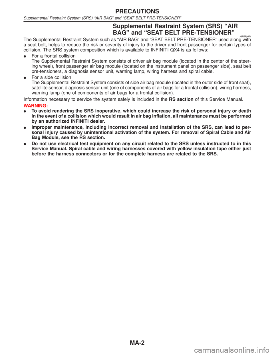
Supplemental Restraint System (SRS) ªAIR
BAGº and ªSEAT BELT PRE-TENSIONERº
NBMA0001The Supplemental Restraint System such as ªAIR BAGº and ªSEAT BELT PRE-TENSIONERº used along with
a seat belt, helps to reduce the risk or severity of injury to the driver and front passenger for certain types of
collision. The SRS system composition which is available to INFINITI QX4 is as follows:
IFor a frontal collision
The Supplemental Restraint System consists of driver air bag module (located in the center of the steer-
ing wheel), front passenger air bag module (located on the instrument panel on passenger side), seat belt
pre-tensioners, a diagnosis sensor unit, warning lamp, wiring harness and spiral cable.
IFor a side collision
The Supplemental Restraint System consists of side air bag module (located in the outer side of front seat),
satellite sensor, diagnosis sensor unit (one of components of air bags for a frontal collision), wiring harness,
warning lamp (one of components of air bags for a frontal collision).
Information necessary to service the system safely is included in theRS sectionof this Service Manual.
WARNING:
ITo avoid rendering the SRS inoperative, which could increase the risk of personal injury or death
in the event of a collision which would result in air bag inflation, all maintenance must be performed
by an authorized INFINITI dealer.
IImproper maintenance, including incorrect removal and installation of the SRS, can lead to per-
sonal injury caused by unintentional activation of the system. For removal of Spiral Cable and Air
Bag Module, see the RS section.
IDo not use electrical test equipment on any circuit related to the SRS unless instructed to in this
Service Manual. Spiral cable and wiring harnesses covered with yellow insulation tape either just
before the harness connectors or for the complete harness are related to the SRS.
PRECAUTIONS
Supplemental Restraint System (SRS) ªAIR BAGº and ªSEAT BELT PRE-TENSIONERº
MA-2
Page 1998 of 2395
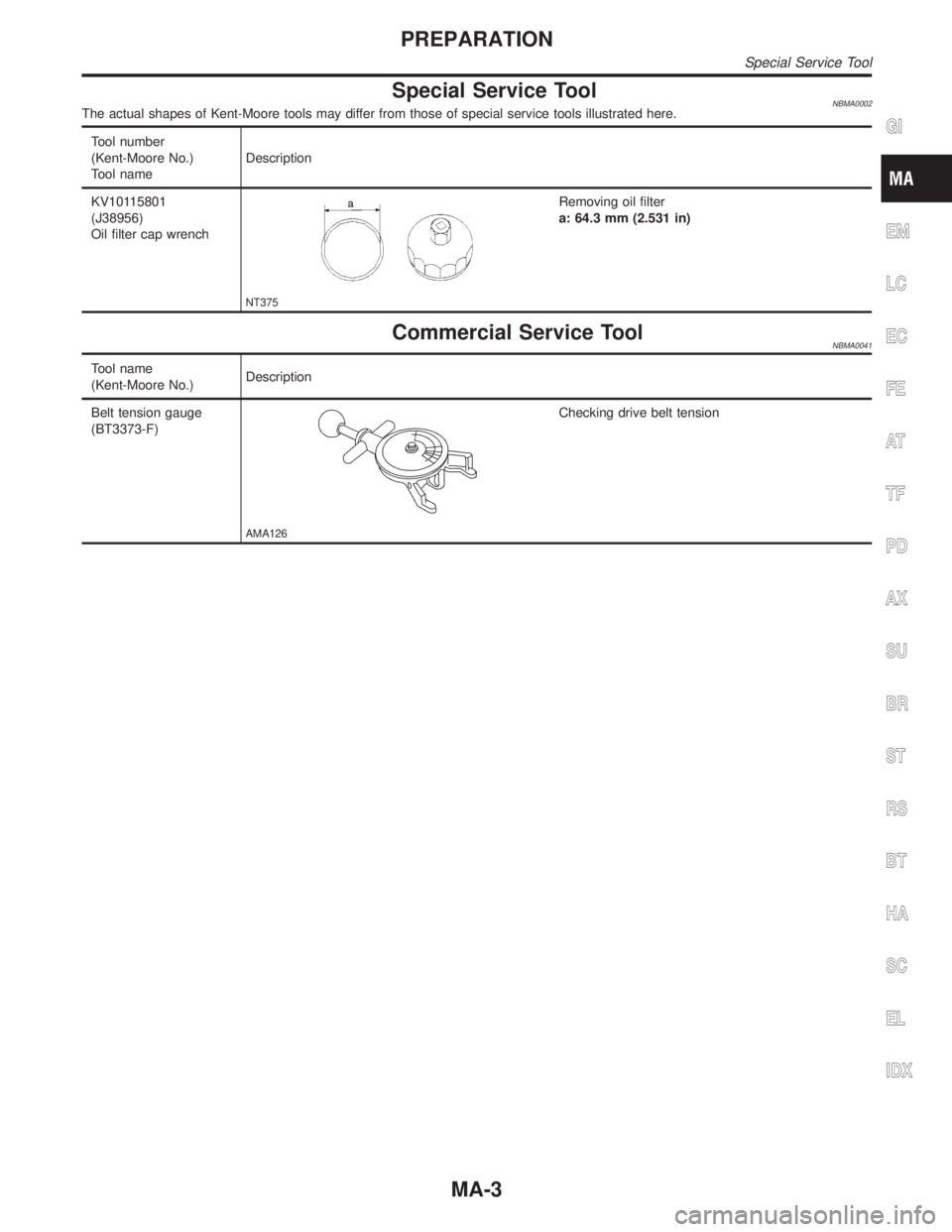
Special Service ToolNBMA0002The actual shapes of Kent-Moore tools may differ from those of special service tools illustrated here.
Tool number
(Kent-Moore No.)
Tool nameDescription
KV10115801
(J38956)
Oil filter cap wrench
NT375
Removing oil filter
a: 64.3 mm (2.531 in)
Commercial Service ToolNBMA0041
Tool name
(Kent-Moore No.)Description
Belt tension gauge
(BT3373-F)
AMA126
Checking drive belt tension
GI
EM
LC
EC
FE
AT
TF
PD
AX
SU
BR
ST
RS
BT
HA
SC
EL
IDX
PREPARATION
Special Service Tool
MA-3
Page 1999 of 2395

NBMA0003
General maintenance includes those items which should be checked during the normal day-to-day operation
of the vehicle. They are essential if the vehicle is to continue operating properly. The owners can perform
checks and inspections themselves or they can have their INFINITI dealers do them.
OUTSIDE THE VEHICLE
The maintenance items listed here should be performed from time to time, unless otherwise specified.
ItemReference page
TiresCheck the pressure with a gauge periodically when at a service station,
including the spare, and adjust to the specified pressure if necessary. Check
carefully for damage, cuts or excessive wear.Ð
Wheel nutsWhen checking the tires, make sure no nuts are missing, and check for any
loose nuts. Tighten if necessary.Ð
Tire rotationTires should be rotated every 12,000 km (7,500 miles). MA-24
Wheel alignment and
balanceIf the vehicle pulls to either side while driving on a straight and level road, or
if you detect uneven or abnormal tire wear, there may be a need for wheel
alignment. If the steering wheel or seat vibrates at normal highway speeds,
wheel balancing may be needed.MA-24, SU-6, ªFront
Wheel Alignmentº
Windshield wiper
bladesCheck for cracks or wear if they do not wipe properly. Ð
Doors and engine
hoodCheck that all doors and the engine hood operate smoothly as well as the
trunk lid and back hatch. Also make sure that all latches lock securely. Lubri-
cate if necessary. Make sure that the secondary latch keeps the hood from
opening when the primary latch is released.
When driving in areas using road salt or other corrosive materials, check
lubrication frequently.MA-27
INSIDE THE VEHICLE
The maintenance items listed here should be checked on a regular basis, such as when performing periodic maintenance, cleaning the
vehicle, etc.
ItemReference page
LampsMake sure that the headlamps, stop lamps, tail lamps, turn signal lamps, and
other lamps are all operating properly and installed securely. Also check
headlamp aim.Ð
Warning lamps and
buzzers/chimesMake sure that all warning lamps and buzzers/chimes are operating properly. Ð
Windshield wiper
and washerCheck that the wipers and washer operate properly and that the wipers do
not streak.Ð
Windshield defrosterCheck that the air comes out of the defroster outlets properly and in sufficient
quantity when operating the heater or air conditioning.Ð
Steering wheelCheck that it has the specified play. Be sure to check for changes in the
steering condition, such as excessive play, hard steering or strange noises.
Free play: Less than 35 mm (1.38 in)Ð
SeatsCheck seat position controls such as seat adjusters, seatback recliner, etc. to
make sure they operate smoothly and that all latches lock securely in every
position. Check that the head restrains move up and down smoothly and that
the locks (if equipped) hold securely in all latched positions. Check that the
latches lock securely for folding-down rear seatbacks.Ð
Seat beltsCheck that all parts of the seat belt system (e.g. buckles, anchors, adjusters
and retractors) operate properly and smoothly and are installed securely.
Check the belt webbing for cuts, fraying, wear or damage.MA-28, RS-7, ªSeat Belt
Inspectionº
BrakesCheck that the brake does not pull the vehicle to one side when applied. Ð
GENERAL MAINTENANCE
MA-4
Page 2024 of 2395
Engine Maintenance
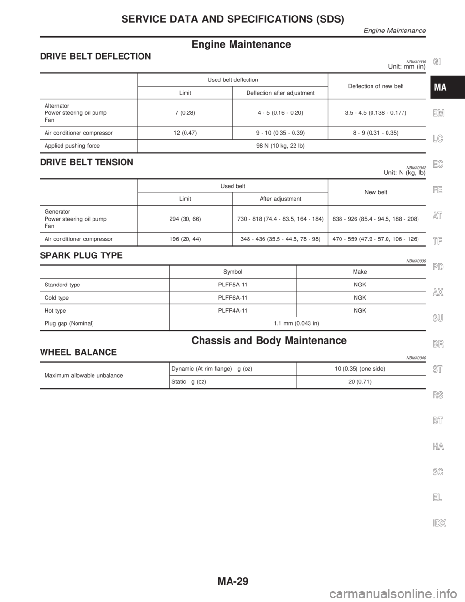
DRIVE BELT DEFLECTIONNBMA0038Unit: mm (in)
Used belt deflection
Deflection of new belt
Limit Deflection after adjustment
Alternator
Power steering oil pump
Fan7 (0.28)4 - 5 (0.16 - 0.20) 3.5 - 4.5 (0.138 - 0.177)
Air conditioner compressor 12 (0.47) 9 - 10 (0.35 - 0.39)8 - 9 (0.31 - 0.35)
Applied pushing force 98 N (10 kg, 22 lb)
DRIVE BELT TENSIONNBMA0042Unit: N (kg, lb)
Used belt
New belt
Limit After adjustment
Generator
Power steering oil pump
Fan294 (30, 66) 730 - 818 (74.4 - 83.5, 164 - 184) 838 - 926 (85.4 - 94.5, 188 - 208)
Air conditioner compressor 196 (20, 44) 348 - 436 (35.5 - 44.5, 78 - 98) 470 - 559 (47.9 - 57.0, 106 - 126)
SPARK PLUG TYPENBMA0039
Symbol Make
Standard type PLFR5A-11 NGK
Cold type PLFR6A-11 NGK
Hot type PLFR4A-11 NGK
Plug gap (Nominal) 1.1 mm (0.043 in)
Chassis and Body Maintenance
WHEEL BALANCENBMA0040
Maximum allowable unbalanceDynamic (At rim flange) g (oz) 10 (0.35) (one side)
Static g (oz) 20 (0.71)
GI
EM
LC
EC
FE
AT
TF
PD
AX
SU
BR
ST
RS
BT
HA
SC
EL
IDX
SERVICE DATA AND SPECIFICATIONS (SDS)
Engine Maintenance
MA-29
Page 2026 of 2395
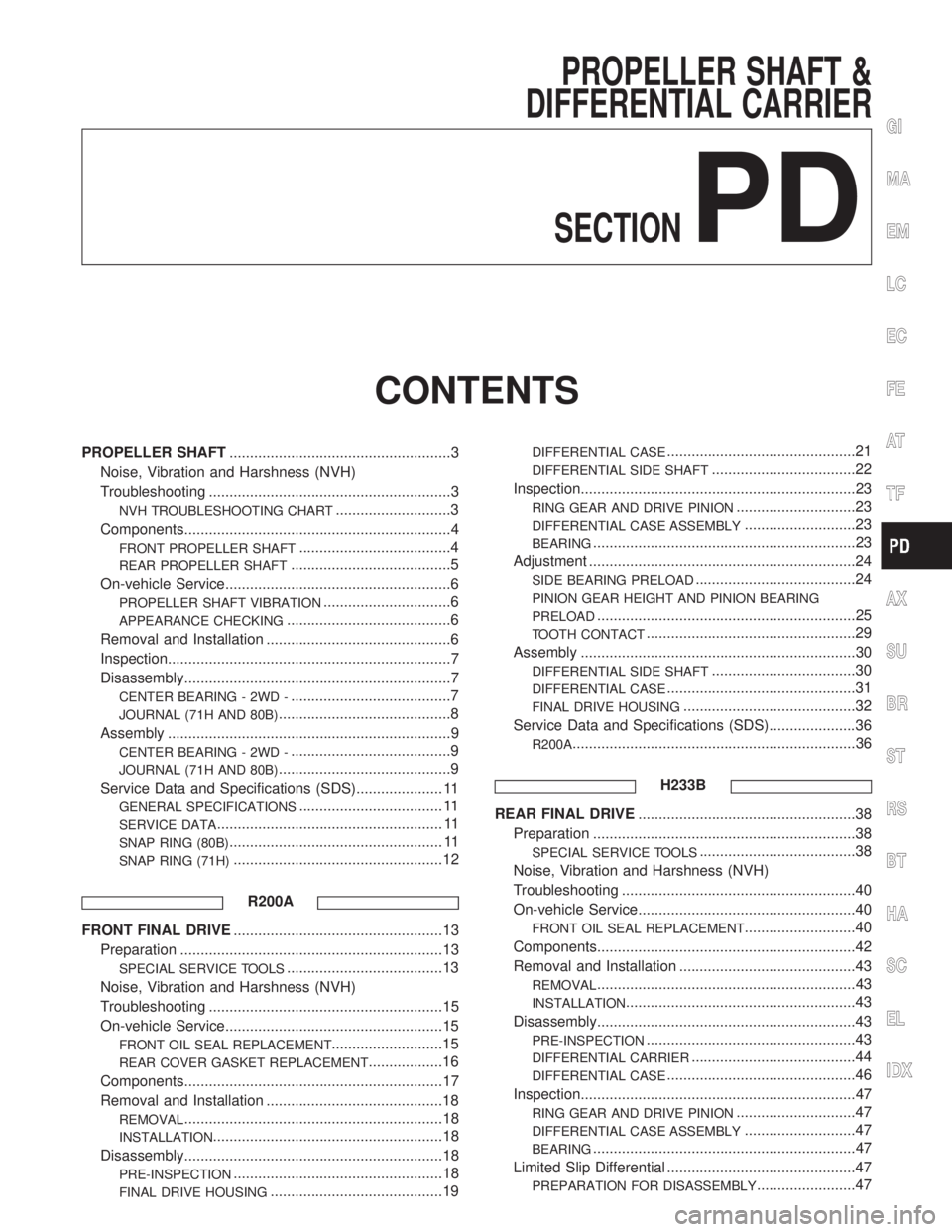
PROPELLER SHAFT &
DIFFERENTIAL CARRIER
SECTION
PD
CONTENTS
PROPELLER SHAFT......................................................3
Noise, Vibration and Harshness (NVH)
Troubleshooting ...........................................................3
NVH TROUBLESHOOTING CHART............................3
Components.................................................................4
FRONT PROPELLER SHAFT.....................................4
REAR PROPELLER SHAFT.......................................5
On-vehicle Service.......................................................6
PROPELLER SHAFT VIBRATION...............................6
APPEARANCE CHECKING........................................6
Removal and Installation .............................................6
Inspection.....................................................................7
Disassembly.................................................................7
CENTER BEARING - 2WD -.......................................7
JOURNAL (71H AND 80B)..........................................8
Assembly .....................................................................9
CENTER BEARING - 2WD -.......................................9
JOURNAL (71H AND 80B)..........................................9
Service Data and Specifications (SDS)..................... 11
GENERAL SPECIFICATIONS................................... 11
SERVICE DATA....................................................... 11
SNAP RING (80B).................................................... 11
SNAP RING (71H)...................................................12
R200A
FRONT FINAL DRIVE...................................................13
Preparation ................................................................13
SPECIAL SERVICE TOOLS......................................13
Noise, Vibration and Harshness (NVH)
Troubleshooting .........................................................15
On-vehicle Service.....................................................15
FRONT OIL SEAL REPLACEMENT...........................15
REAR COVER GASKET REPLACEMENT..................16
Components...............................................................17
Removal and Installation ...........................................18
REMOVAL...............................................................18
INSTALLATION........................................................18
Disassembly...............................................................18
PRE-INSPECTION...................................................18
FINAL DRIVE HOUSING..........................................19
DIFFERENTIAL CASE..............................................21
DIFFERENTIAL SIDE SHAFT...................................22
Inspection...................................................................23
RING GEAR AND DRIVE PINION.............................23
DIFFERENTIAL CASE ASSEMBLY...........................23
BEARING................................................................23
Adjustment .................................................................24
SIDE BEARING PRELOAD.......................................24
PINION GEAR HEIGHT AND PINION BEARING
PRELOAD
...............................................................25
TOOTH CONTACT...................................................29
Assembly ...................................................................30
DIFFERENTIAL SIDE SHAFT...................................30
DIFFERENTIAL CASE..............................................31
FINAL DRIVE HOUSING..........................................32
Service Data and Specifications (SDS).....................36
R200A.....................................................................36
H233B
REAR FINAL DRIVE.....................................................38
Preparation ................................................................38
SPECIAL SERVICE TOOLS......................................38
Noise, Vibration and Harshness (NVH)
Troubleshooting .........................................................40
On-vehicle Service.....................................................40
FRONT OIL SEAL REPLACEMENT...........................40
Components...............................................................42
Removal and Installation ...........................................43
REMOVAL...............................................................43
INSTALLATION........................................................43
Disassembly...............................................................43
PRE-INSPECTION...................................................43
DIFFERENTIAL CARRIER........................................44
DIFFERENTIAL CASE..............................................46
Inspection...................................................................47
RING GEAR AND DRIVE PINION.............................47
DIFFERENTIAL CASE ASSEMBLY...........................47
BEARING................................................................47
Limited Slip Differential ..............................................47
PREPARATION FOR DISASSEMBLY........................47
GI
MA
EM
LC
EC
FE
AT
TF
AX
SU
BR
ST
RS
BT
HA
SC
EL
IDX
Page 2027 of 2395
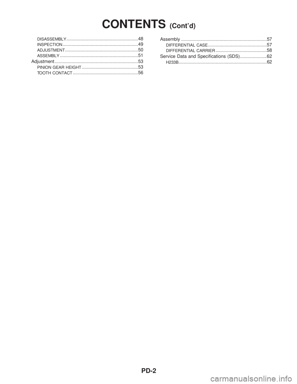
DISASSEMBLY........................................................48
INSPECTION...........................................................49
ADJUSTMENT.........................................................50
ASSEMBLY.............................................................51
Adjustment .................................................................53
PINION GEAR HEIGHT............................................53
TOOTH CONTACT...................................................56Assembly ...................................................................57
DIFFERENTIAL CASE..............................................57
DIFFERENTIAL CARRIER........................................58
Service Data and Specifications (SDS).....................62
H233B.....................................................................62
CONTENTS(Cont'd)
PD-2
Page 2031 of 2395
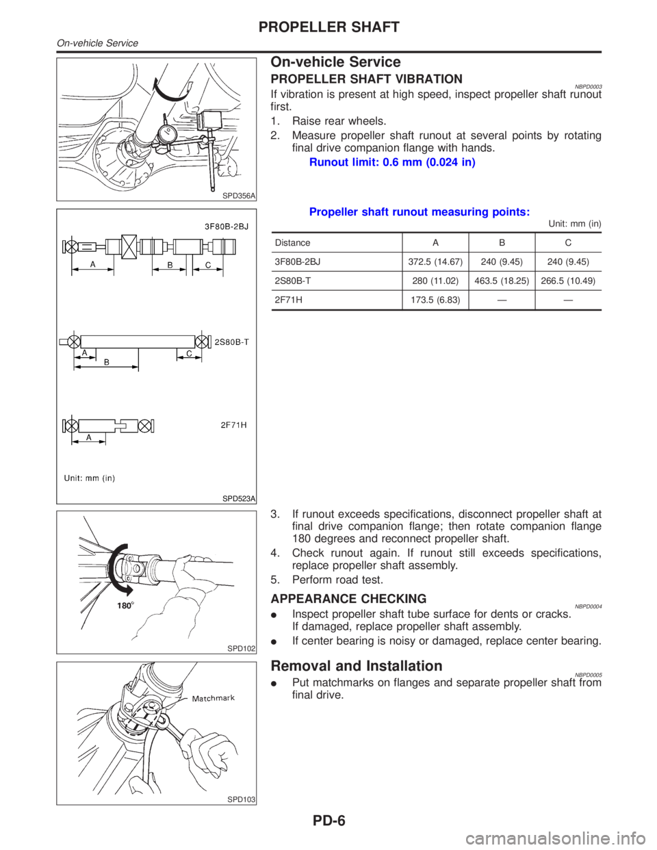
SPD356A
On-vehicle Service
PROPELLER SHAFT VIBRATIONNBPD0003If vibration is present at high speed, inspect propeller shaft runout
first.
1. Raise rear wheels.
2. Measure propeller shaft runout at several points by rotating
final drive companion flange with hands.
Runout limit: 0.6 mm (0.024 in)
SPD523A
Propeller shaft runout measuring points:
Unit: mm (in)
Distance A B C
3F80B-2BJ 372.5 (14.67) 240 (9.45) 240 (9.45)
2S80B-T 280 (11.02) 463.5 (18.25) 266.5 (10.49)
2F71H 173.5 (6.83) Ð Ð
SPD102
3. If runout exceeds specifications, disconnect propeller shaft at
final drive companion flange; then rotate companion flange
180 degrees and reconnect propeller shaft.
4. Check runout again. If runout still exceeds specifications,
replace propeller shaft assembly.
5. Perform road test.
APPEARANCE CHECKINGNBPD0004IInspect propeller shaft tube surface for dents or cracks.
If damaged, replace propeller shaft assembly.
IIf center bearing is noisy or damaged, replace center bearing.
SPD103
Removal and InstallationNBPD0005IPut matchmarks on flanges and separate propeller shaft from
final drive.
PROPELLER SHAFT
On-vehicle Service
PD-6
Page 2036 of 2395
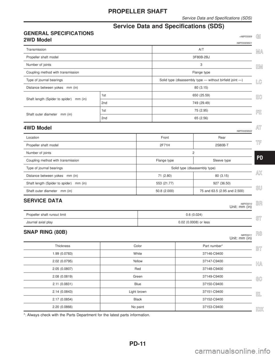
Service Data and Specifications (SDS)
GENERAL SPECIFICATIONS=NBPD00092WD ModelNBPD0009S01
TransmissionA/T
Propeller shaft model3F80B-2BJ
Number of joints3
Coupling method with transmissionFlange type
Type of journal bearings Solid type (disassembly type Ð without birfield joint Ð)
Distance between yokes mm (in)80 (3.15)
Shaft length (Spider to spider) mm (in)1st 650 (25.59)
2nd 749 (29.49)
Shaft outer diameter mm (in)1st 75 (2.95)
2nd 65 (2.56)
4WD ModelNBPD0009S02
LocationFront Rear
Propeller shaft model 2F71H 2S80B-T
Number of joints2
Coupling method with transmission Flange type Sleeve type
Type of journal bearingsSolid type (disassembly type)
Distance between yokes mm (in) 71 (2.80) 80 (3.15)
Shaft length (Spider to spider) mm (in) 553 (21.77) 927 (36.50)
Shaft outer diameter mm (in) 50.8 (2.000) 75 and 63.5 (2.95 and 2.500)
SERVICE DATANBPD0010Unit: mm (in)
Propeller shaft runout limit0.6 (0.024)
Journal axial play0.02 (0.0008) or less
SNAP RING (80B)NBPD0011Unit: mm (in)
Thickness Color Part number*
1.99 (0.0783) White 37146-C9400
2.02 (0.0795) Yellow 37147-C9400
2.05 (0.0807) Red 37148-C9400
2.08 (0.0819) Green 37149-C9400
2.11 (0.0831) Blue 37150-C9400
2.14 (0.0843) Light brown 37151-C9400
2.17 (0.0854) Black 37152-C9400
2.20 (0.0866) No paint 37153-C9400
*: Always check with the Parts Department for the latest parts information.
GI
MA
EM
LC
EC
FE
AT
TF
AX
SU
BR
ST
RS
BT
HA
SC
EL
IDX
PROPELLER SHAFT
Service Data and Specifications (SDS)
PD-11