Page 1810 of 2395
HFC-134a (R-134a) Service Tools and
Equipment
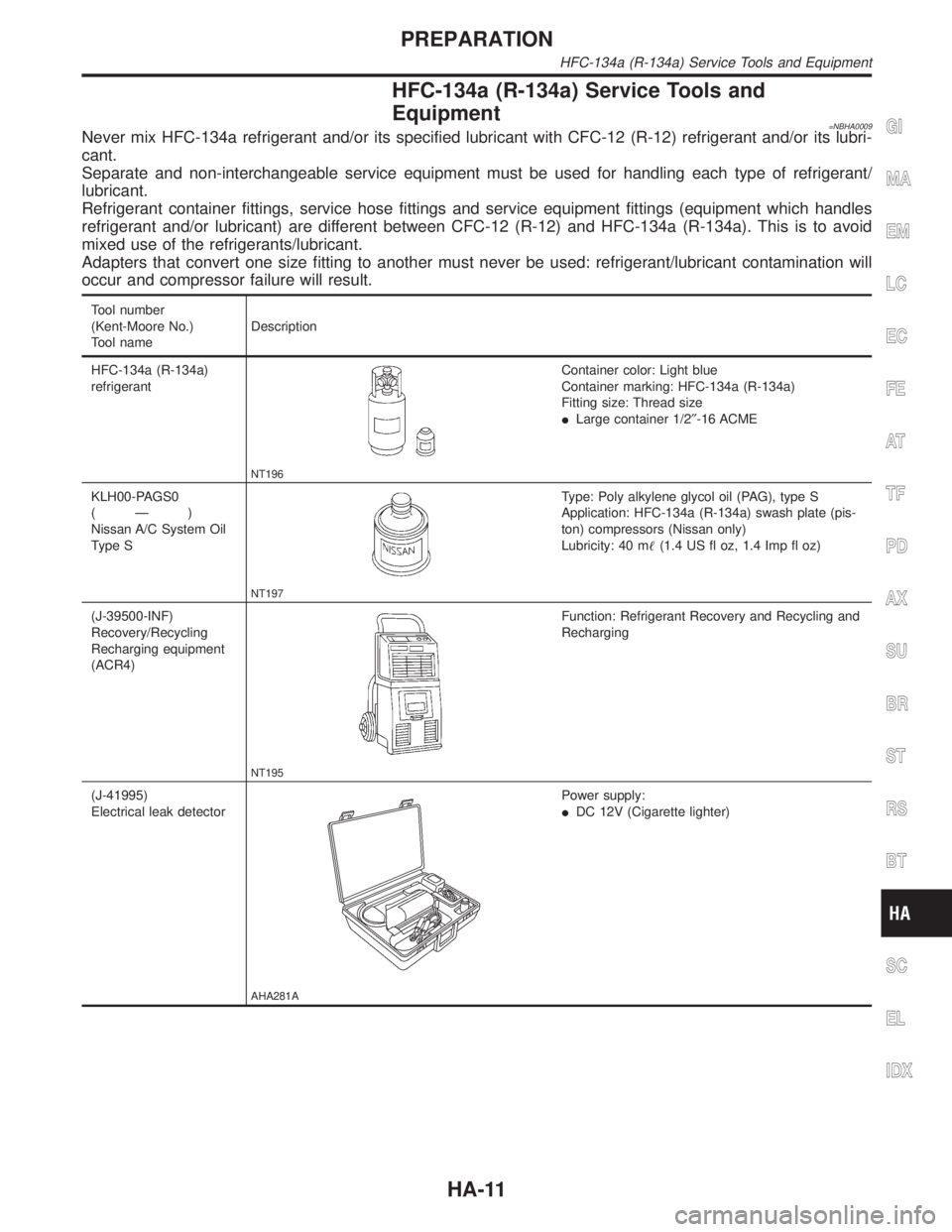
=NBHA0009Never mix HFC-134a refrigerant and/or its specified lubricant with CFC-12 (R-12) refrigerant and/or its lubri-
cant.
Separate and non-interchangeable service equipment must be used for handling each type of refrigerant/
lubricant.
Refrigerant container fittings, service hose fittings and service equipment fittings (equipment which handles
refrigerant and/or lubricant) are different between CFC-12 (R-12) and HFC-134a (R-134a). This is to avoid
mixed use of the refrigerants/lubricant.
Adapters that convert one size fitting to another must never be used: refrigerant/lubricant contamination will
occur and compressor failure will result.
Tool number
(Kent-Moore No.)
Tool nameDescription
HFC-134a (R-134a)
refrigerant
NT196
Container color: Light blue
Container marking: HFC-134a (R-134a)
Fitting size: Thread size
ILarge container 1/2²-16 ACME
KLH00-PAGS0
(Ð)
Nissan A/C System Oil
Type S
NT197
Type: Poly alkylene glycol oil (PAG), type S
Application: HFC-134a (R-134a) swash plate (pis-
ton) compressors (Nissan only)
Lubricity: 40 m(1.4 US fl oz, 1.4 Imp fl oz)
(J-39500-INF)
Recovery/Recycling
Recharging equipment
(ACR4)
NT195
Function: Refrigerant Recovery and Recycling and
Recharging
(J-41995)
Electrical leak detector
AHA281A
Power supply:
IDC 12V (Cigarette lighter)
GI
MA
EM
LC
EC
FE
AT
TF
PD
AX
SU
BR
ST
RS
BT
SC
EL
IDX
PREPARATION
HFC-134a (R-134a) Service Tools and Equipment
HA-11
Page 1811 of 2395
Tool number
(Kent-Moore No.)
Tool nameDescription
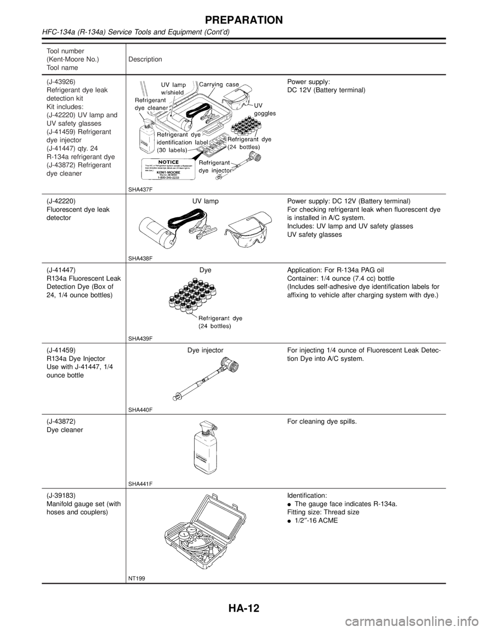
(J-43926)
Refrigerant dye leak
detection kit
Kit includes:
(J-42220) UV lamp and
UV safety glasses
(J-41459) Refrigerant
dye injector
(J-41447) qty. 24
R-134a refrigerant dye
(J-43872) Refrigerant
dye cleaner
SHA437F
Power supply:
DC 12V (Battery terminal)
(J-42220)
Fluorescent dye leak
detectorUV lamp
SHA438F
Power supply: DC 12V (Battery terminal)
For checking refrigerant leak when fluorescent dye
is installed in A/C system.
Includes: UV lamp and UV safety glasses
UV safety glasses
(J-41447)
R134a Fluorescent Leak
Detection Dye (Box of
24, 1/4 ounce bottles)Dye
SHA439F
Application: For R-134a PAG oil
Container: 1/4 ounce (7.4 cc) bottle
(Includes self-adhesive dye identification labels for
affixing to vehicle after charging system with dye.)
(J-41459)
R134a Dye Injector
Use with J-41447, 1/4
ounce bottleDye injector
SHA440F
For injecting 1/4 ounce of Fluorescent Leak Detec-
tion Dye into A/C system.
(J-43872)
Dye cleaner
SHA441F
For cleaning dye spills.
(J-39183)
Manifold gauge set (with
hoses and couplers)
NT199
Identification:
IThe gauge face indicates R-134a.
Fitting size: Thread size
I1/2²-16 ACME
PREPARATION
HFC-134a (R-134a) Service Tools and Equipment (Cont'd)
HA-12
Page 1812 of 2395
Tool number
(Kent-Moore No.)
Tool nameDescription
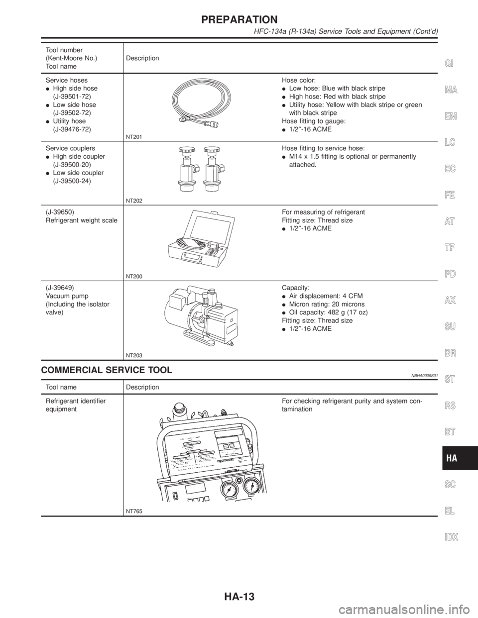
Service hoses
IHigh side hose
(J-39501-72)
ILow side hose
(J-39502-72)
IUtility hose
(J-39476-72)
NT201
Hose color:
ILow hose: Blue with black stripe
IHigh hose: Red with black stripe
IUtility hose: Yellow with black stripe or green
with black stripe
Hose fitting to gauge:
I1/2²-16 ACME
Service couplers
IHigh side coupler
(J-39500-20)
ILow side coupler
(J-39500-24)
NT202
Hose fitting to service hose:
IM14 x 1.5 fitting is optional or permanently
attached.
(J-39650)
Refrigerant weight scale
NT200
For measuring of refrigerant
Fitting size: Thread size
I1/2²-16 ACME
(J-39649)
Vacuum pump
(Including the isolator
valve)
NT203
Capacity:
IAir displacement: 4 CFM
IMicron rating: 20 microns
IOil capacity: 482 g (17 oz)
Fitting size: Thread size
I1/2²-16 ACME
COMMERCIAL SERVICE TOOLNBHA0009S01
Tool name Description
Refrigerant identifier
equipment
NT765
For checking refrigerant purity and system con-
tamination
GI
MA
EM
LC
EC
FE
AT
TF
PD
AX
SU
BR
ST
RS
BT
SC
EL
IDX
PREPARATION
HFC-134a (R-134a) Service Tools and Equipment (Cont'd)
HA-13
Page 1943 of 2395
HFC-134a (R-134a) Service ProcedureNBHA0070SETTING OF SERVICE TOOLS AND EQUIPMENTNBHA0070S01DISCHARGING REFRIGERANTNBHA0070S0101WARNING:
Avoid breathing A/C refrigerant and lubricant vapor or mist. Exposure may irritate eyes, nose and
throat. Remove HFC-134a (R-134a) from A/C system using certified service equipment meeting require-
ments of SAE J2210 (R-134a recycling equipment) or J2209 (R-134a recovery equipment). If acciden-
tal system discharge occurs, ventilate work area before resuming service. Additional health and safety
information may be obtained from refrigerant and lubricant manufacturers.
SHA179FA
Evacuating System and Charging RefrigerantNBHA0070S0102
SHA180FA
SERVICE PROCEDURE
HFC-134a (R-134a) Service Procedure
HA-144
Page 1944 of 2395
SHA251FA
*1: HA-146
*2: HA-155*3: HA-157
*4: HA-114*5: HA-2
GI
MA
EM
LC
EC
FE
AT
TF
PD
AX
SU
BR
ST
RS
BT
SC
EL
IDX
SERVICE PROCEDURE
HFC-134a (R-134a) Service Procedure (Cont'd)
HA-145
Page 1945 of 2395
Maintenance of Lubricant Quantity in
Compressor
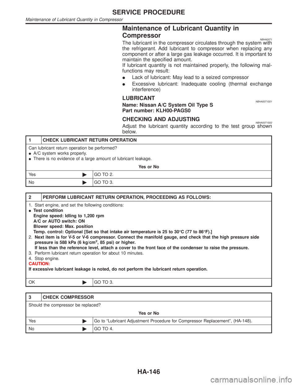
NBHA0071The lubricant in the compressor circulates through the system with
the refrigerant. Add lubricant to compressor when replacing any
component or after a large gas leakage occurred. It is important to
maintain the specified amount.
If lubricant quantity is not maintained properly, the following mal-
functions may result:
ILack of lubricant: May lead to a seized compressor
IExcessive lubricant: Inadequate cooling (thermal exchange
interference)
LUBRICANTNBHA0071S01Name: Nissan A/C System Oil Type S
Part number: KLH00-PAGS0
CHECKING AND ADJUSTINGNBHA0071S02Adjust the lubricant quantity according to the test group shown
below.
1 CHECK LUBRICANT RETURN OPERATION
Can lubricant return operation be performed?
IA/C system works properly.
IThere is no evidence of a large amount of lubricant leakage.
YesorNo
Ye s©GO TO 2.
No©GO TO 3.
2 PERFORM LUBRICANT RETURN OPERATION, PROCEEDING AS FOLLOWS:
1. Start engine, and set the following conditions:
ITest condition
Engine speed: Idling to 1,200 rpm
A/C or AUTO switch: ON
Blower speed: Max. position
Temp. control: Optional [Set so that intake air temperature is 25 to 30ÉC (77 to 86ÉF).]
2.Next item is for V-5 or V-6 compressor. Connect the manifold gauge, and check that the high pressure side
pressure is 588 kPa (6 kg/cm
2, 85 psi) or higher.
If less than the reference level, attach a cover to the front face of the condenser to raise the pressure.
3. Perform lubricant return operation for about 10 minutes.
4. Stop engine.
CAUTION:
If excessive lubricant leakage is noted, do not perform the lubricant return operation.
OK©GO TO 3.
3 CHECK COMPRESSOR
Should the compressor be replaced?
YesorNo
Ye s©Go to ªLubricant Adjustment Procedure for Compressor Replacementº, (HA-148).
No©GO TO 4.
SERVICE PROCEDURE
Maintenance of Lubricant Quantity in Compressor
HA-146
Page 1946 of 2395
4 CHECK ANY PART
Is there any part to be replaced? (Evaporator, condenser, liquid tank or in case there is evidence of a large amount of
lubricant leakage.)
YesorNo
Ye s©Go to ªLubricant Adjusting Procedure for Components Replacement Except
Compressorº, (HA-148).
No©Carry out the A/C performance test.GI
MA
EM
LC
EC
FE
AT
TF
PD
AX
SU
BR
ST
RS
BT
SC
EL
IDX
SERVICE PROCEDURE
Maintenance of Lubricant Quantity in Compressor (Cont'd)
HA-147
Page 1947 of 2395
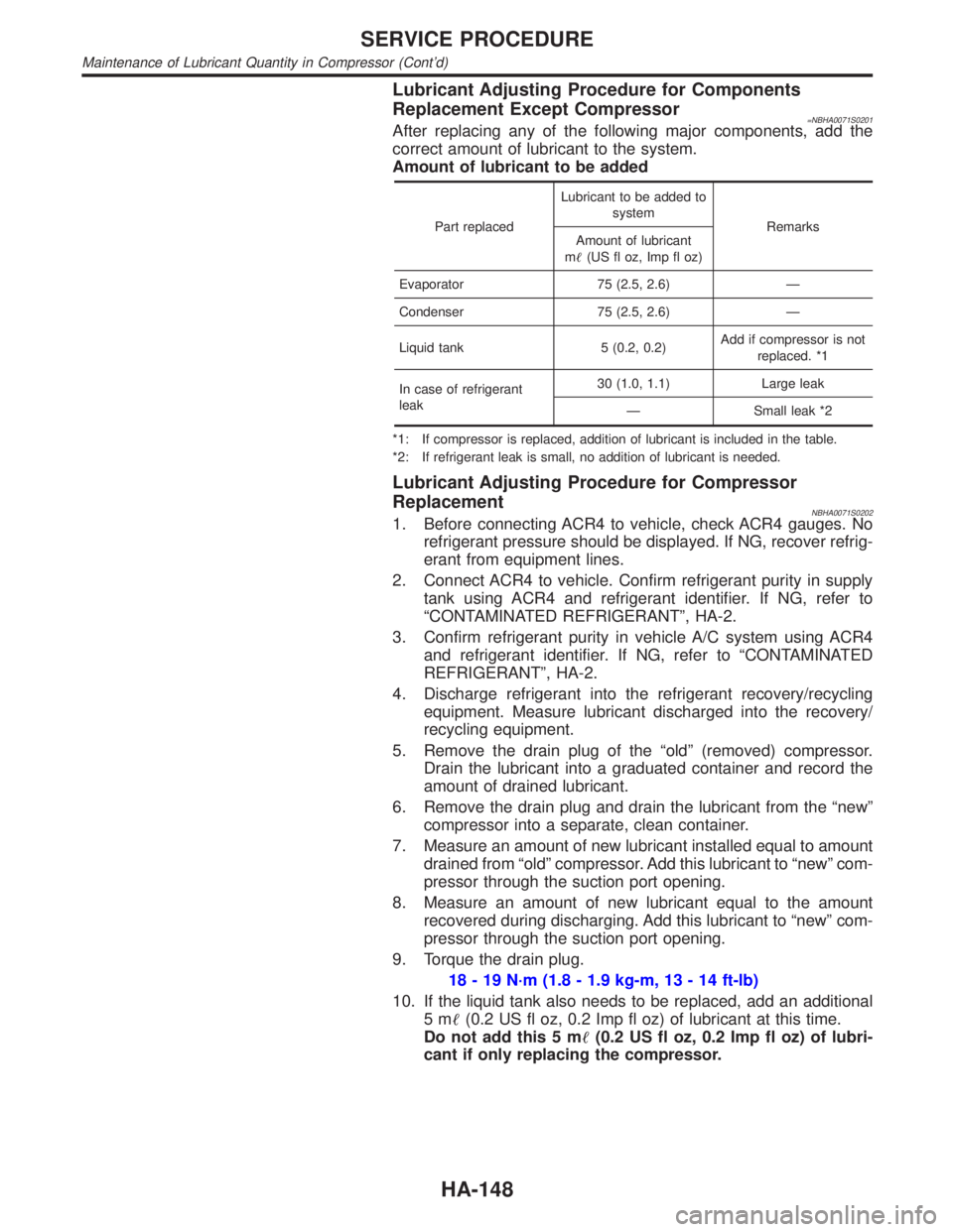
Lubricant Adjusting Procedure for Components
Replacement Except Compressor
=NBHA0071S0201After replacing any of the following major components, add the
correct amount of lubricant to the system.
Amount of lubricant to be added
Part replacedLubricant to be added to
system
Remarks
Amount of lubricant
m(US fl oz, Imp fl oz)
Evaporator 75 (2.5, 2.6) Ð
Condenser 75 (2.5, 2.6) Ð
Liquid tank 5 (0.2, 0.2)Add if compressor is not
replaced. *1
In case of refrigerant
leak30 (1.0, 1.1) Large leak
Ð Small leak *2
*1: If compressor is replaced, addition of lubricant is included in the table.
*2: If refrigerant leak is small, no addition of lubricant is needed.
Lubricant Adjusting Procedure for Compressor
Replacement
NBHA0071S02021. Before connecting ACR4 to vehicle, check ACR4 gauges. No
refrigerant pressure should be displayed. If NG, recover refrig-
erant from equipment lines.
2. Connect ACR4 to vehicle. Confirm refrigerant purity in supply
tank using ACR4 and refrigerant identifier. If NG, refer to
ªCONTAMINATED REFRIGERANTº, HA-2.
3. Confirm refrigerant purity in vehicle A/C system using ACR4
and refrigerant identifier. If NG, refer to ªCONTAMINATED
REFRIGERANTº, HA-2.
4. Discharge refrigerant into the refrigerant recovery/recycling
equipment. Measure lubricant discharged into the recovery/
recycling equipment.
5. Remove the drain plug of the ªoldº (removed) compressor.
Drain the lubricant into a graduated container and record the
amount of drained lubricant.
6. Remove the drain plug and drain the lubricant from the ªnewº
compressor into a separate, clean container.
7. Measure an amount of new lubricant installed equal to amount
drained from ªoldº compressor. Add this lubricant to ªnewº com-
pressor through the suction port opening.
8. Measure an amount of new lubricant equal to the amount
recovered during discharging. Add this lubricant to ªnewº com-
pressor through the suction port opening.
9. Torque the drain plug.
18 - 19 N´m (1.8 - 1.9 kg-m, 13 - 14 ft-lb)
10. If the liquid tank also needs to be replaced, add an additional
5m(0.2 US fl oz, 0.2 Imp fl oz) of lubricant at this time.
Do not add this 5 m(0.2 US fl oz, 0.2 Imp fl oz) of lubri-
cant if only replacing the compressor.
SERVICE PROCEDURE
Maintenance of Lubricant Quantity in Compressor (Cont'd)
HA-148