Page 1709 of 2395

SEM843E
SEM321AA
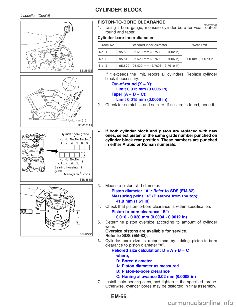
PISTON-TO-BORE CLEARANCENBEM0027S061. Using a bore gauge, measure cylinder bore for wear, out-of-
round and taper.
Cylinder bore inner diameter
Grade No. Standard inner diameter Wear limit
No. 1 95.500 - 95.510 mm (3.7598 - 3.7602 in)
0.20 mm (0.0079 in) No. 2 95.510 - 95.520 mm (3.7602 - 3.7606 in)
No. 3 95.520 - 95.530 mm (3.7606 - 3.7610 in)
If it exceeds the limit, rebore all cylinders. Replace cylinder
block if necessary.
Out-of-round (X þ Y):
Limit 0.015 mm (0.0006 in)
Taper (AþBþC):
Limit 0.015 mm (0.0006 in)
2. Check for scratches and seizure. If seizure is found, hone it.
SEM451G
IIf both cylinder block and piston are replaced with new
ones, select piston of the same grade number punched on
cylinder block rear position. These numbers are punched
in either Arabic or Roman numerals.
SEM258C
3. Measure piston skirt diameter.
Piston diameter ªAº: Refer to SDS (EM-82).
Measuring point ªaº (Distance from the top):
41.0 mm (1.61 in)
4. Check that piston-to-bore clearance is within specification.
Piston-to-bore clearance ªBº:
0.010 - 0.030 mm (0.0004 - 0.0012 in)
5. Determine piston oversize according to amount of cylinder
wear.
Oversize pistons are available for service.
Refer to SDS (EM-82).
6. Cylinder bore size is determined by adding piston-to-bore
clearance to piston diameter ªAº.
Rebored size calculation: D = A+BþC
where,
D: Bored diameter
A: Piston diameter as measured
B: Piston-to-bore clearance
C: Honing allowance 0.02 mm (0.0008 in)
7. Install main bearing caps, and tighten to the specified torque.
Otherwise, cylinder bores may be distorted in final assembly.
CYLINDER BLOCK
Inspection (Cont'd)
EM-66
Page 1711 of 2395

SEM845E
2. Install main bearing cap and bearing beam to cylinder block.
Tighten all bolts in correct order.
3. Measure inner diameters ªAº of each main bearing.
AEM033
4. Measure outer diameters ªDmº of each crankshaft main jour-
nal.
5. Calculate main bearing clearance.
Main bearing clearance = A þ Dm
Standard: 0.035 - 0.045 mm (0.0014 - 0.0018 in)
Limit: 0.065 mm (0.0026 in)
IIf it exceeds the limit, replace bearing.
IIf clearance cannot be adjusted using any standard bearing
grade, grind crankshaft journal and use undersized bearing.
SEM964
a. When grinding crankshaft journal, confirm that ªLº dimension in
fillet roll is more than the specified limit.
ªLº: 0.1 mm (0.004 in)
b. Refer to SDS for grinding crankshaft and available service
parts.
SEM451G
6. If crankshaft or cylinder block is replaced with a new one,
select thickness of main bearings as follows:
a. Grade number of each cylinder block main journal is punched
on the respective cylinder block. These numbers are punched
in either Arabic or Alphabet. Refer to SDS, EM-81.
If measured diameter is out of grade punched, decide suitable
grade using table in SDS.
SEM452G
b. Grade number of each crankshaft main journal is punched on
the respective crankshaft. These numbers are punched in
either Arabic or Alphabet. Refer to SDS, EM-84.
If measured diameter is out of grade punched, decide suitable
grade using table in SDS.
c. Select main bearing with suitable thickness according to the
following table.
Refer to ªSDSº, EM-85, for available main bearings.
CYLINDER BLOCK
Inspection (Cont'd)
EM-68
Page 1718 of 2395
General SpecificationsNBEM0029
Cylinder arrangementV- 6
Displacement cm
3(cu in)3,498 (213.45)
Bore and stroke mm (in)95.5 x 81.4 (3.760 x 3.205)
Valve arrangementDOHC
Firing order1-2-3-4-5-6
Number of piston ringsCompression 2
Oil 1
Number of main bearings4
Compression ratio10.0
Compression PressureNBEM0030Unit: kPa (kg/cm2, psi)/300 rpm
Compression pressureStandard 1,275 (13.0, 185)
Minimum 981 (10.0, 142)
Differential limit between cylinders 98 (1.0, 14)
Cylinder number
SEM713A
Cylinder HeadNBEM0031Unit: mm (in)
Standard Limit
Head surface distortion Less than 0.03 (0.0012) 0.1 (0.004)
SEM949E
GI
MA
LC
EC
FE
AT
TF
PD
AX
SU
BR
ST
RS
BT
HA
SC
EL
IDX
SERVICE DATA AND SPECIFICATIONS (SDS)
General Specifications
EM-75
Page 1719 of 2395

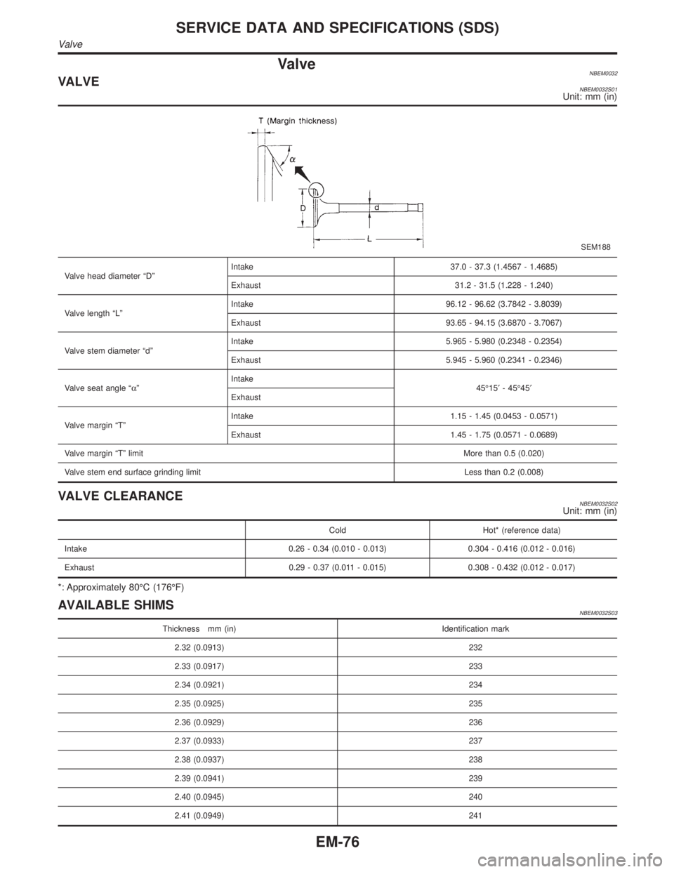
ValveNBEM0032VALVENBEM0032S01Unit: mm (in)
SEM188
Valve head diameter ªDºIntake 37.0 - 37.3 (1.4567 - 1.4685)
Exhaust 31.2 - 31.5 (1.228 - 1.240)
Valve length ªLºIntake 96.12 - 96.62 (3.7842 - 3.8039)
Exhaust 93.65 - 94.15 (3.6870 - 3.7067)
Valve stem diameter ªdºIntake 5.965 - 5.980 (0.2348 - 0.2354)
Exhaust 5.945 - 5.960 (0.2341 - 0.2346)
Valve seat angle ªaºIntake
45É15¢- 45É45¢
Exhaust
Valve margin ªTºIntake 1.15 - 1.45 (0.0453 - 0.0571)
Exhaust 1.45 - 1.75 (0.0571 - 0.0689)
Valve margin ªTº limitMore than 0.5 (0.020)
Valve stem end surface grinding limit Less than 0.2 (0.008)
VALVE CLEARANCENBEM0032S02Unit: mm (in)
Cold Hot* (reference data)
Intake 0.26 - 0.34 (0.010 - 0.013) 0.304 - 0.416 (0.012 - 0.016)
Exhaust 0.29 - 0.37 (0.011 - 0.015) 0.308 - 0.432 (0.012 - 0.017)
*: Approximately 80ÉC (176ÉF)
AVAILABLE SHIMSNBEM0032S03
Thickness mm (in) Identification mark
2.32 (0.0913) 232
2.33 (0.0917) 233
2.34 (0.0921) 234
2.35 (0.0925) 235
2.36 (0.0929) 236
2.37 (0.0933) 237
2.38 (0.0937) 238
2.39 (0.0941) 239
2.40 (0.0945) 240
2.41 (0.0949) 241
SERVICE DATA AND SPECIFICATIONS (SDS)
Valve
EM-76
Page 1720 of 2395
Thickness mm (in) Identification mark
2.42 (0.0953) 242
2.43 (0.0957) 243
2.44 (0.0961) 244
2.45 (0.0965) 245
2.46 (0.0969) 246
2.47 (0.0972) 247
2.48 (0.0976) 248
2.49 (0.0980) 249
2.50 (0.0984) 250
2.51 (0.0988) 251
2.52 (0.0992) 252
2.53 (0.0996) 253
2.54 (0.1000) 254
2.55 (0.1004) 255
2.56 (0.1008) 256
2.57 (0.1012) 257
2.58 (0.1016) 258
2.59 (0.1020) 259
2.60 (0.1024) 260
2.61 (0.1028) 261
2.62 (0.1031) 262
2.63 (0.1035) 263
2.64 (0.1039) 264
2.65 (0.1043) 265
2.66 (0.1047) 266
2.67 (0.1051) 267
2.68 (0.1055) 268
2.69 (0.1059) 269
2.70 (0.1063) 270
2.71 (0.1067) 271
2.72 (0.1071) 272
2.73 (0.1075) 273
2.74 (0.1079) 274
2.75 (0.1083) 275
2.76 (0.1087) 276
2.77 (0.1091) 277
2.78 (0.1094) 278
2.79 (0.1098) 279
2.80 (0.1102) 280
2.81 (0.1106) 281
GI
MA
LC
EC
FE
AT
TF
PD
AX
SU
BR
ST
RS
BT
HA
SC
EL
IDX
SERVICE DATA AND SPECIFICATIONS (SDS)
Valve (Cont'd)
EM-77
Page 1721 of 2395
Thickness mm (in) Identification mark
2.82 (0.1110) 282
2.83 (0.1114) 283
2.84 (0.1118) 284
2.85 (0.1122) 285
2.86 (0.1126) 286
2.87 (0.1130) 287
2.88 (0.1134) 288
2.89 (0.1138) 289
2.90 (0.1142) 290
2.91 (0.1146) 291
2.92 (0.1150) 292
2.93 (0.1154) 293
2.94 (0.1157) 294
2.95 (0.1161) 295
SEM966E
VALVE SPRINGNBEM0032S04
Free height mm (in)47.10 (1.8543)
Pressure N (kg, lb) at height mm (in)Standard 202 (20.6, 45.4) at 37.0 (1.457)
Limit 436 (44.5, 98.1) at 28.2 (1.110)
Out-of-square mm (in)Less than 2.0 (0.079)
VALVE LIFTERNBEM0032S05Unit: mm (in)
Valve lifter outer diameter 34.960 - 34.975 (1.3764 - 1.3770)
Lifter guide inner diameter 35.000 - 35.021 (1.3780 - 1.3788)
Clearance between lifter and lifter guide 0.025 - 0.061 (0.0010 - 0.0024)
SERVICE DATA AND SPECIFICATIONS (SDS)
Valve (Cont'd)
EM-78
Page 1722 of 2395
VALVE GUIDENBEM0032S06Unit: mm (in)
SEM950E
Standard Service
Valve guide Outer diameter 10.023 - 10.034 (0.3946 - 0.3950) 10.223 - 10.234 (0.4025 - 0.4029)
Valve guide Inner diameter (Finished size) 6.000 - 6.018 (0.2362 - 0.2369)
Cylinder head valve guide hole diameter 9.975 - 9.996 (0.3927 - 0.3935) 10.175 - 10.196 (0.4006 - 0.4014)
Interference fit of valve guide 0.027 - 0.059 (0.0011 - 0.0023)
Standard Max. tolerance
Stem to guide clearanceIntake 0.020 - 0.053 (0.0008 - 0.0021) 0.08 (0.0031)
Exhaust 0.040 - 0.073 (0.0016 - 0.0029) 0.1 (0.004)
Valve deflection limitIntake Ð 0.24 (0.0094)
Exhaust Ð 0.28 (0.0110)
Projection length ªLº12.6 - 12.8 (0.496 - 0.504)
Valve SeatNBEM0033Unit: mm (in)
SEM021EB
GI
MA
LC
EC
FE
AT
TF
PD
AX
SU
BR
ST
RS
BT
HA
SC
EL
IDX
SERVICE DATA AND SPECIFICATIONS (SDS)
Valve (Cont'd)
EM-79
Page 1723 of 2395

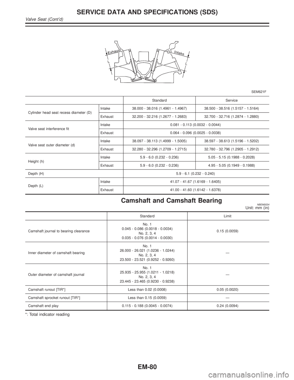
SEM621F
Standard Service
Cylinder head seat recess diameter (D)Intake 38.000 - 38.016 (1.4961 - 1.4967) 38.500 - 38.516 (1.5157 - 1.5164)
Exhaust 32.200 - 32.216 (1.2677 - 1.2683) 32.700 - 32.716 (1.2874 - 1.2880)
Valve seat interference fitIntake 0.081 - 0.113 (0.0032 - 0.0044)
Exhaust 0.064 - 0.096 (0.0025 - 0.0038)
Valve seat outer diameter (d)Intake 38.097 - 38.113 (1.4999 - 1.5005) 38.597 - 38.613 (1.5196 - 1.5202)
Exhaust 32.280 - 32.296 (1.2709 - 1.2715) 32.780 - 32.796 (1.2905 - 1.2912)
Height (h)Intake 5.9 - 6.0 (0.232 - 0.236) 5.05 - 5.15 (0.1988 - 0.2028)
Exhaust 5.9 - 6.0 (0.232 - 0.236) 4.95 - 5.05 (0.1949 - 0.1988)
Depth (H)5.9 - 6.1 (0.232 - 0.240)
Depth (L)Intake 41.07 - 41.67 (1.6169 - 1.6405)
Exhaust 41.00 - 41.60 (1.6142 - 1.6378)
Camshaft and Camshaft BearingNBEM0034Unit: mm (in)
Standard Limit
Camshaft journal to bearing clearanceNo. 1
0.045 - 0.086 (0.0018 - 0.0034)
No. 2, 3, 4
0.035 - 0.076 (0.0014 - 0.0030)0.15 (0.0059)
Inner diameter of camshaft bearingNo. 1
26.000 - 26.021 (1.0236 - 1.0244)
No. 2, 3, 4
23.500 - 23.521 (0.9252 - 0.9260)Ð
Outer diameter of camshaft journalNo. 1
25.935 - 25.955 (1.0211 - 1.0218)
No. 2, 3, 4
23.445 - 23.465 (0.9230 - 0.9238)Ð
Camshaft runout [TIR*] Less than 0.02 (0.0008) 0.05 (0.0020)
Camshaft sprocket runout [TIR*] Less than 0.15 (0.0059) Ð
Camshaft end play 0.115 - 0.188 (0.0045 - 0.0074) 0.24 (0.0094)
*: Total indicator reading
SERVICE DATA AND SPECIFICATIONS (SDS)
Valve Seat (Cont'd)
EM-80