Page 1948 of 2395
RHA065DD
Compressor
REMOVAL AND INSTALLATIONNBHA0072
RHA892H
GI
MA
EM
LC
EC
FE
AT
TF
PD
AX
SU
BR
ST
RS
BT
SC
EL
IDX
SERVICE PROCEDURE
Maintenance of Lubricant Quantity in Compressor (Cont'd)
HA-149
Page 1949 of 2395
Compressor Clutch
OVERHAULNBHA0073
RHA122F
RHA136EB
REMOVALNBHA0074IWhen removing center bolt, hold clutch disc with clutch disc
wrench.
RHA399F
RHA124F
IRemove the clutch disc using the clutch disc puller.
Insert the holder's three pins into the holes in the clutch disc.
Rotate the holder clockwise to hook it onto the plate. Then,
tighten the center bolt to remove the clutch disc.
After removing the clutch disc, remove the shims from either
the drive shaft or the clutch disc.
SERVICE PROCEDURE
Compressor Clutch
HA-150
Page 1950 of 2395

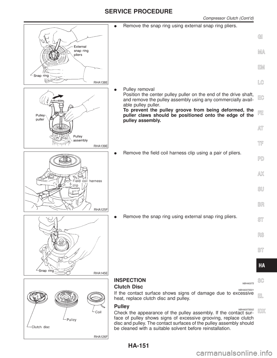
RHA138E
IRemove the snap ring using external snap ring pliers.
RHA139E
IPulley removal
Position the center pulley puller on the end of the drive shaft,
and remove the pulley assembly using any commercially avail-
able pulley puller.
To prevent the pulley groove from being deformed, the
puller claws should be positioned onto the edge of the
pulley assembly.
RHA125F
IRemove the field coil harness clip using a pair of pliers.
RHA145E
IRemove the snap ring using external snap ring pliers.
RHA126F
INSPECTIONNBHA0075Clutch DiscNBHA0075S01If the contact surface shows signs of damage due to excessive
heat, replace clutch disc and pulley.
PulleyNBHA0075S02Check the appearance of the pulley assembly. If the contact sur-
face of pulley shows signs of excessive grooving, replace clutch
disc and pulley. The contact surfaces of the pulley assembly should
be cleaned with a suitable solvent before reinstallation.
GI
MA
EM
LC
EC
FE
AT
TF
PD
AX
SU
BR
ST
RS
BT
SC
EL
IDX
SERVICE PROCEDURE
Compressor Clutch (Cont'd)
HA-151
Page 1951 of 2395
CoilNBHA0075S03Check coil for loose connection or cracked insulation.
RHA142E
INSTALLATIONNBHA0076IInstall the field coil.
Be sure to align the coil's pin with the hole in the com-
pressor's front head.
IInstall the field coil harness clip using a screwdriver.
RHA143EA
IInstall the pulley assembly using the installer and a hand
press, and then install the snap ring using snap ring pliers.
RHA127F
IInstall the clutch disc on the drive shaft, together with the
original shim(s). Press the clutch disc down by hand.
RHA086E
IUsing the holder to prevent clutch disc rotation, tighten the bolt
to 14 N´m (1.4 kg-m, 10 ft-lb) torque.
After tightening the bolt, check that the pulley rotates
smoothly.
SERVICE PROCEDURE
Compressor Clutch (Cont'd)
HA-152
Page 1952 of 2395
RHA087E
ICheck clearance around the entire periphery of clutch disc.
Disc-to-pulley clearance:
0.3 - 0.6 mm (0.012 - 0.024 in)
If the specified clearance is not obtained, replace adjusting
spacer and readjust.
Break-in OperationNBHA0076S01When replacing compressor clutch assembly, always carry out the
break-in operation. This is done by engaging and disengaging the
clutch about thirty times. Break-in operation raises the level of
transmitted torque.
GI
MA
EM
LC
EC
FE
AT
TF
PD
AX
SU
BR
ST
RS
BT
SC
EL
IDX
SERVICE PROCEDURE
Compressor Clutch (Cont'd)
HA-153
Page 1953 of 2395
Refrigerant Lines
REMOVAL AND INSTALLATION=NBHA0077IRefer to page HA-4 regarding ªPrecautions for Refrigerant Connectionº.
RHA838H
SERVICE PROCEDURE
Refrigerant Lines
HA-154
Page 1954 of 2395

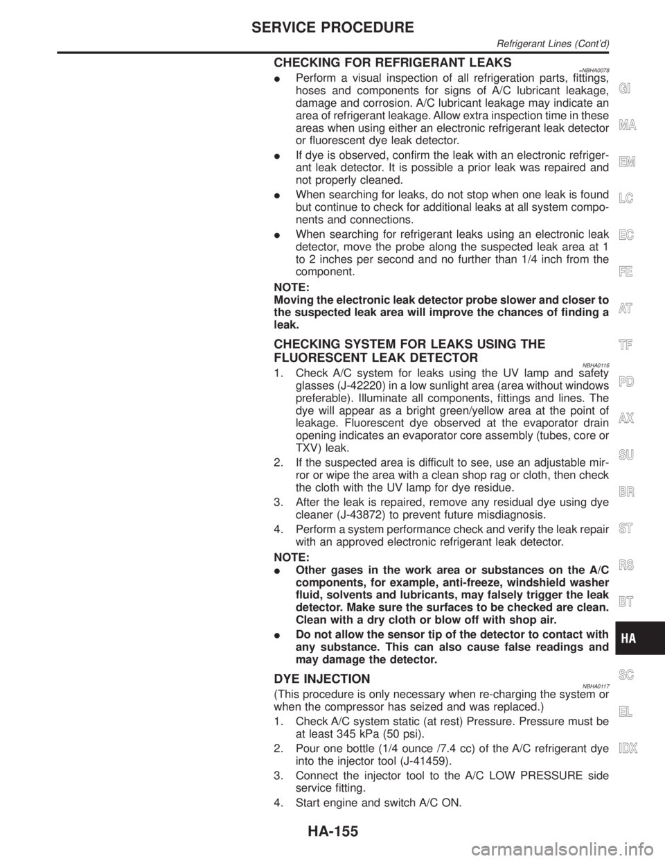
CHECKING FOR REFRIGERANT LEAKS=NBHA0078IPerform a visual inspection of all refrigeration parts, fittings,
hoses and components for signs of A/C lubricant leakage,
damage and corrosion. A/C lubricant leakage may indicate an
area of refrigerant leakage. Allow extra inspection time in these
areas when using either an electronic refrigerant leak detector
or fluorescent dye leak detector.
IIf dye is observed, confirm the leak with an electronic refriger-
ant leak detector. It is possible a prior leak was repaired and
not properly cleaned.
IWhen searching for leaks, do not stop when one leak is found
but continue to check for additional leaks at all system compo-
nents and connections.
IWhen searching for refrigerant leaks using an electronic leak
detector, move the probe along the suspected leak area at 1
to 2 inches per second and no further than 1/4 inch from the
component.
NOTE:
Moving the electronic leak detector probe slower and closer to
the suspected leak area will improve the chances of finding a
leak.
CHECKING SYSTEM FOR LEAKS USING THE
FLUORESCENT LEAK DETECTOR
NBHA01161. Check A/C system for leaks using the UV lamp and safety
glasses (J-42220) in a low sunlight area (area without windows
preferable). Illuminate all components, fittings and lines. The
dye will appear as a bright green/yellow area at the point of
leakage. Fluorescent dye observed at the evaporator drain
opening indicates an evaporator core assembly (tubes, core or
TXV) leak.
2. If the suspected area is difficult to see, use an adjustable mir-
ror or wipe the area with a clean shop rag or cloth, then check
the cloth with the UV lamp for dye residue.
3. After the leak is repaired, remove any residual dye using dye
cleaner (J-43872) to prevent future misdiagnosis.
4. Perform a system performance check and verify the leak repair
with an approved electronic refrigerant leak detector.
NOTE:
IOther gases in the work area or substances on the A/C
components, for example, anti-freeze, windshield washer
fluid, solvents and lubricants, may falsely trigger the leak
detector. Make sure the surfaces to be checked are clean.
Clean with a dry cloth or blow off with shop air.
IDo not allow the sensor tip of the detector to contact with
any substance. This can also cause false readings and
may damage the detector.
DYE INJECTIONNBHA0117(This procedure is only necessary when re-charging the system or
when the compressor has seized and was replaced.)
1. Check A/C system static (at rest) Pressure. Pressure must be
at least 345 kPa (50 psi).
2. Pour one bottle (1/4 ounce /7.4 cc) of the A/C refrigerant dye
into the injector tool (J-41459).
3. Connect the injector tool to the A/C LOW PRESSURE side
service fitting.
4. Start engine and switch A/C ON.
GI
MA
EM
LC
EC
FE
AT
TF
PD
AX
SU
BR
ST
RS
BT
SC
EL
IDX
SERVICE PROCEDURE
Refrigerant Lines (Cont'd)
HA-155
Page 1955 of 2395

5. When the A/C operating (compressor running), inject one
bottle (1/4 ounce /7.4 cc) of fluorescent dye through the low-
pressure service valve using dye injector tool J-41459 (refer to
the manufacture's operating instructions).
6. With the engine still running, disconnect the injector tool from
the service fitting.
CAUTION:
Be careful not to allow dye to spray or drip when disconnect-
ing the injector from the system.
NOTE:
If repairing the A/C system or replacing a component, pour the
dye directly into the open system connection and proceed
with the service procedures.
7. Operate the A/C system for a minimum of 20 minutes to mix
the dye with the system oil. Depending on the leak size, oper-
ating conditions and location of the leak, it may take from min-
utes to days for the dye to penetrate a leak and become visible.
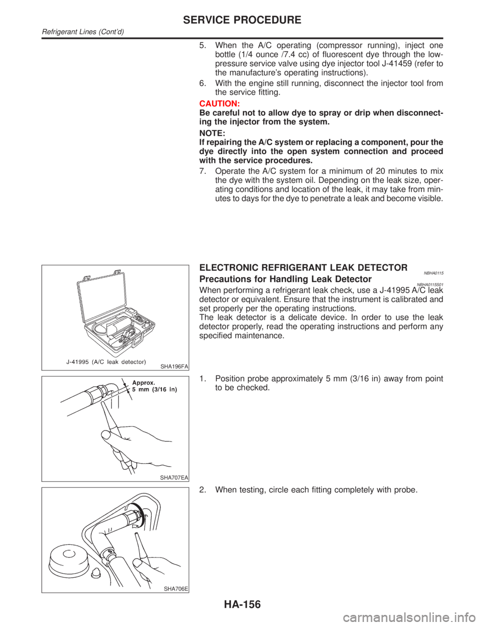
SHA196FA
ELECTRONIC REFRIGERANT LEAK DETECTORNBHA0115Precautions for Handling Leak DetectorNBHA0115S01When performing a refrigerant leak check, use a J-41995 A/C leak
detector or equivalent. Ensure that the instrument is calibrated and
set properly per the operating instructions.
The leak detector is a delicate device. In order to use the leak
detector properly, read the operating instructions and perform any
specified maintenance.
SHA707EA
1. Position probe approximately 5 mm (3/16 in) away from point
to be checked.
SHA706E
2. When testing, circle each fitting completely with probe.
SERVICE PROCEDURE
Refrigerant Lines (Cont'd)
HA-156