Page 655 of 2395

SYSTEM Ð ENGINE MECHANICAL & OTHERNBEC0041S02
SYMPTOM
Reference
section
HARD/NO START/RESTART (EXCP. HA)
ENGINE STALL
HESITATION/SURGING/FLAT SPOT
SPARK KNOCK/DETONATION
LACK OF POWER/POOR ACCELERATION
HIGH IDLE/LOW IDLE
ROUGH IDLE/HUNTING
IDLING VIBRATION
SLOW/NO RETURN TO IDLE
OVERHEATS/WATER TEMPERATURE HIGH
EXCESSIVE FUEL CONSUMPTION
EXCESSIVE OIL CONSUMPTION
BATTERY DEAD (UNDER CHARGE)
Warranty symptom code AA AB AC AD AE AF AG AH AJ AK AL AM HA
Fuel Fuel tank
5
5FE section
Fuel piping 5 5 5 5 5 5
Ð Vapor lock
Valve deposit
5 555 5 5 5
Poor fuel (Heavy weight gasoline,
Low octane)
Air Air duct
55555 5 Air cleaner
Air leakage from air duct
(Mass air flow sensor Ð throttle
body)
555 5
Throttle body, Throttle wireFE section
Air leakage from intake manifold/
Collector/GasketÐ
Cranking Battery
111111 11
EL section Alternator circuit
Starter circuit 3
Flywheel/Drive plate 6 EM section
PNP switch 4 AT section
1 - 6: The numbers refer to the order of inspection.
(continued on next page)
TROUBLE DIAGNOSIS Ð GENERAL DESCRIPTION
Symptom Matrix Chart (Cont'd)
EC-120
Page 896 of 2395

11 CHECK EVAP CANISTER
Weigh the EVAP canister with the EVAP canister vent control valve attached.
The weight should be less than 1.8 kg (4.0 lb).
OK or NG
OK (With CONSULT-II)©GO TO 13.
OK (Without CONSULT-
II)©GO TO 14.
NG©GO TO 12.
12 DETECT MALFUNCTIONING PART
Check the following.
IEVAP canister for damage
IEVAP hose between EVAP canister and water separator for clogging or poor connection
©Repair hose or replace EVAP canister.
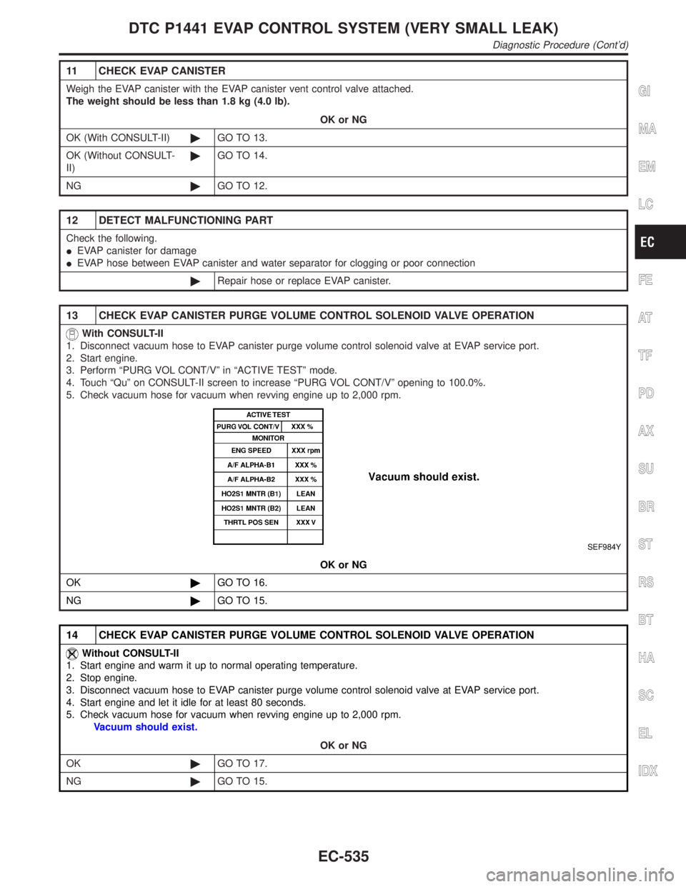
13 CHECK EVAP CANISTER PURGE VOLUME CONTROL SOLENOID VALVE OPERATION
With CONSULT-II
1. Disconnect vacuum hose to EVAP canister purge volume control solenoid valve at EVAP service port.
2. Start engine.
3. Perform ªPURG VOL CONT/Vº in ªACTIVE TESTº mode.
4. Touch ªQuº on CONSULT-II screen to increase ªPURG VOL CONT/Vº opening to 100.0%.
5. Check vacuum hose for vacuum when revving engine up to 2,000 rpm.
SEF984Y
OK or NG
OK©GO TO 16.
NG©GO TO 15.
14 CHECK EVAP CANISTER PURGE VOLUME CONTROL SOLENOID VALVE OPERATION
Without CONSULT-II
1. Start engine and warm it up to normal operating temperature.
2. Stop engine.
3. Disconnect vacuum hose to EVAP canister purge volume control solenoid valve at EVAP service port.
4. Start engine and let it idle for at least 80 seconds.
5. Check vacuum hose for vacuum when revving engine up to 2,000 rpm.
Vacuum should exist.
OK or NG
OK©GO TO 17.
NG©GO TO 15.
GI
MA
EM
LC
FE
AT
TF
PD
AX
SU
BR
ST
RS
BT
HA
SC
EL
IDX
DTC P0440 EVAP CONTROL SYSTEM (SMALL LEAK) (NEGATIVE PRESSURE)
Diagnostic Procedure (Cont'd)
EC-361
Page 927 of 2395
18 CHECK WATER SEPARATOR
1. Check visually for insect nests in the water separator air inlet.
2. Check visually for cracks or flaws in the appearance.
3. Check visually for cracks or flaws in the hose.
4. Check thatAandCare not clogged by blowing air intoBwithA, and thenCplugged.
SEF829T
5. In case of NG in items2-4,replace the parts.
NOTE:
IDo not disassemble water separator.
OK or NG
OK©GO TO 19.
NG©Replace water separator.
19 CHECK IF EVAP CANISTER SATURATED WITH WATER
1. Remove EVAP canister with EVAP canister vent control valve attached.
2. Check if water will drain from the EVAP canister.
SEF596U
YesorNo
Ye s©GO TO 20.
No©GO TO 22.
20 CHECK EVAP CANISTER
Weigh the EVAP canister with the EVAP canister vent control valve attached.
The weight should be less than 1.8 kg (4.0 lb).
OK or NG
OK©GO TO 22.
NG©GO TO 21.
DTC P0450 EVAPORATIVE EMISSION (EVAP) CONTROL SYSTEM PRESSURE
SENSOR
Diagnostic Procedure (Cont'd)
EC-392
Page 1070 of 2395

11 CHECK EVAP CANISTER
Weigh the EVAP canister with the EVAP canister vent control valve attached.
The weight should be less than 1.8 kg (4.0 lb).
OK or NG
OK (With CONSULT-II)©GO TO 13.
OK (Without CONSULT-
II)©GO TO 14.
NG©GO TO 12.
12 DETECT MALFUNCTIONING PART
Check the following.
IEVAP canister for damage
IEVAP hose between EVAP canister and water separator for clogging or poor connection
©Repair hose or replace EVAP canister.
13 CHECK EVAP CANISTER PURGE VOLUME CONTROL SOLENOID VALVE OPERATION
With CONSULT-II
1. Disconnect vacuum hose to EVAP canister purge volume control solenoid valve at EVAP service port.
2. Start engine.
3. Perform ªPURG VOL CONT/Vº in ªACTIVE TESTº mode.
4. Touch ªQuº on CONSULT-II screen to increase ªPURG VOL CONT/Vº opening to 100.0%.
5. Check vacuum hose for vacuum when revving engine up to 2,000 rpm.
SEF984Y
OK or NG
OK©GO TO 16.
NG©GO TO 15.
14 CHECK EVAP CANISTER PURGE VOLUME CONTROL SOLENOID VALVE OPERATION
Without CONSULT-II
1. Start engine and warm it up to normal operating temperature.
2. Stop engine.
3. Disconnect vacuum hose to EVAP canister purge volume control solenoid valve at EVAP service port.
4. Start engine and let it idle for at least 80 seconds.
5. Check vacuum hose for vacuum when revving engine up to 2,000 rpm.
Vacuum should exist.
OK or NG
OK©GO TO 17.
NG©GO TO 15.
GI
MA
EM
LC
FE
AT
TF
PD
AX
SU
BR
ST
RS
BT
HA
SC
EL
IDX
DTC P1441 EVAP CONTROL SYSTEM (VERY SMALL LEAK)
Diagnostic Procedure (Cont'd)
EC-535
Page 1086 of 2395
13 CHECK IF EVAP CANISTER SATURATED WITH WATER
1. Remove EVAP canister with EVAP canister vent control valve attached.
2. Check if water will drain from the EVAP canister.
SEF596U
YesorNo
Ye s©GO TO 14.
No©GO TO 17.
14 CHECK EVAP CANISTER
Weigh the EVAP canister with the EVAP canister vent control valve attached.
The weight should be less than 1.8 kg (4.0 lb).
OK or NG
OK©GO TO 16.
NG©GO TO 15.
15 DETECT MALFUNCTIONING PART
Check the following.
IEVAP canister for damage
IEVAP hose between EVAP canister and water separater for clogging or poor connection
©Repair hose or replace EVAP canister.
GI
MA
EM
LC
FE
AT
TF
PD
AX
SU
BR
ST
RS
BT
HA
SC
EL
IDX
DTC P1444 EVAP CANISTER PURGE VOLUME CONTROL SOLENOID VALVE
Diagnostic Procedure (Cont'd)
EC-551
Page 1093 of 2395

5 CHECK EVAP CANISTER VENT CONTROL VALVE-III
1. Clean the air passage (PortionAtoB) of EVAP canister vent control valve using an air blower.
2. Perform the procedure 4 again.
OK or NG
OK©GO TO 6.
NG©Replace EVAP canister vent control valve.
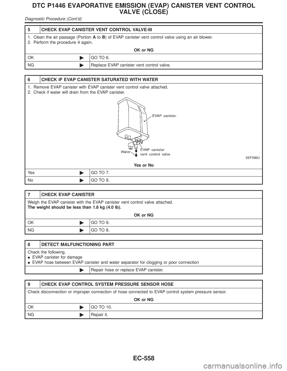
6 CHECK IF EVAP CANISTER SATURATED WITH WATER
1. Remove EVAP canister with EVAP canister vent control valve attached.
2. Check if water will drain from the EVAP canister.
SEF596U
YesorNo
Ye s©GO TO 7.
No©GO TO 9.
7 CHECK EVAP CANISTER
Weigh the EVAP canister with the EVAP canister vent control valve attached.
The weight should be less than 1.8 kg (4.0 lb).
OK or NG
OK©GO TO 9.
NG©GO TO 8.
8 DETECT MALFUNCTIONING PART
Check the following.
IEVAP canister for damage
IEVAP hose between EVAP canister and water separator for clogging or poor connection
©Repair hose or replace EVAP canister.
9 CHECK EVAP CONTROL SYSTEM PRESSURE SENSOR HOSE
Check disconnection or improper connection of hose connected to EVAP control system pressure sensor.
OK or NG
OK©GO TO 10.
NG©Repair it.
DTC P1446 EVAPORATIVE EMISSION (EVAP) CANISTER VENT CONTROL
VALVE (CLOSE)
Diagnostic Procedure (Cont'd)
EC-558
Page 1114 of 2395

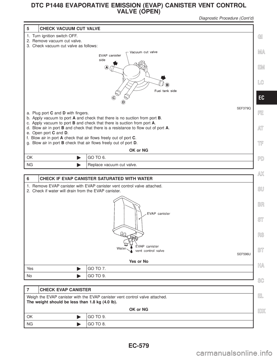
5 CHECK VACUUM CUT VALVE
1. Turn ignition switch OFF.
2. Remove vacuum cut valve.
3. Check vacuum cut valve as follows:
SEF379Q
a. Plug portCandDwith fingers.
b. Apply vacuum to portAand check that there is no suction from portB.
c. Apply vacuum to portBand check that there is suction from portA.
d. Blow air in portBand check that there is a resistance to flow out of portA.
e. Open portCandD.
f. Blow air in portAcheck that air flows freely out of portC.
g. Blow air in portBcheck that air flows freely out of portD.
OK or NG
OK©GO TO 6.
NG©Replace vacuum cut valve.
6 CHECK IF EVAP CANISTER SATURATED WITH WATER
1. Remove EVAP canister with EVAP canister vent control valve attached.
2. Check if water will drain from the EVAP canister.
SEF596U
YesorNo
Ye s©GO TO 7.
No©GO TO 9.
7 CHECK EVAP CANISTER
Weigh the EVAP canister with the EVAP canister vent control valve attached.
The weight should be less than 1.8 kg (4.0 lb).
OK or NG
OK©GO TO 9.
NG©GO TO 8.
GI
MA
EM
LC
FE
AT
TF
PD
AX
SU
BR
ST
RS
BT
HA
SC
EL
IDX
DTC P1448 EVAPORATIVE EMISSION (EVAP) CANISTER VENT CONTROL
VALVE (OPEN)
Diagnostic Procedure (Cont'd)
EC-579
Page 1259 of 2395
SEL350X
Aiming AdjustmentNBEL0029Before performing aiming adjustment, make sure of the following.
1) Keep all tires inflated to correct pressure.
2) Place vehicle on level ground.
3) See that vehicle is unloaded (except for full levels of coolant,
engine oil and fuel, and spare tire, jack, and tools). Have the
driver or equivalent weight placed in driver's seat.
Adjust aiming in the vertical direction by turning the adjusting
screw.
MEL327G
1. Set the distance between the screen and the center of the fog
lamp lens as shown at left.
2. Turn front fog lamps ON.
MEL328GA
3. Adjust front fog lamps so that the top edge of the high inten-
sity zone is 200 mm (7.9 in) below the height of the fog lamp
centers as shown at left.
IWhen performing adjustment, if necessary, cover the head-
lamps and opposite fog lamp.
FRONT FOG LAMP
Aiming Adjustment
EL-74