2001 INFINITI QX4 weight
[x] Cancel search: weightPage 1750 of 2395
SGI285
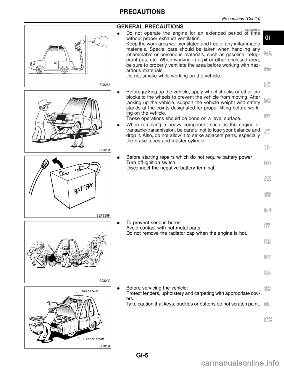
GENERAL PRECAUTIONSNBGI0001S02IDo not operate the engine for an extended period of time
without proper exhaust ventilation.
Keep the work area well ventilated and free of any inflammable
materials. Special care should be taken when handling any
inflammable or poisonous materials, such as gasoline, refrig-
erant gas, etc. When working in a pit or other enclosed area,
be sure to properly ventilate the area before working with haz-
ardous materials.
Do not smoke while working on the vehicle.
SGI231
IBefore jacking up the vehicle, apply wheel chocks or other tire
blocks to the wheels to prevent the vehicle from moving. After
jacking up the vehicle, support the vehicle weight with safety
stands at the points designated for proper lifting before work-
ing on the vehicle.
These operations should be done on a level surface.
IWhen removing a heavy component such as the engine or
transaxle/transmission, be careful not to lose your balance and
drop it. Also, do not allow it to strike adjacent parts, especially
the brake tubes and master cylinder.
SEF289H
IBefore starting repairs which do not require battery power:
Turn off ignition switch.
Disconnect the negative battery terminal.
SGI233
ITo prevent serious burns:
Avoid contact with hot metal parts.
Do not remove the radiator cap when the engine is hot.
SGI234
IBefore servicing the vehicle:
Protect fenders, upholstery and carpeting with appropriate cov-
ers.
Take caution that keys, buckles or buttons do not scratch paint.
MA
EM
LC
EC
FE
AT
TF
PD
AX
SU
BR
ST
RS
BT
HA
SC
EL
IDX
PRECAUTIONS
Precautions (Cont'd)
GI-5
Page 1762 of 2395
SGI862-A
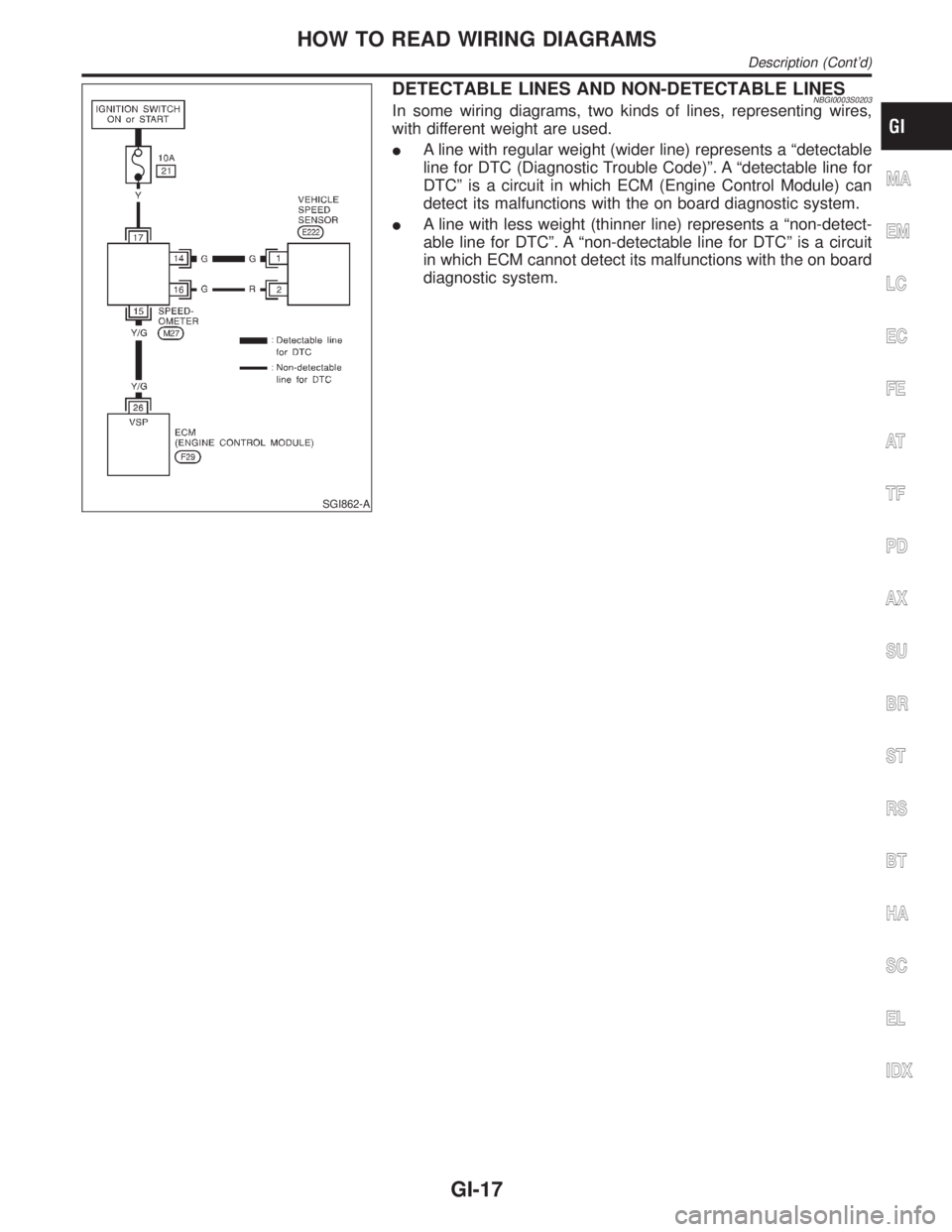
DETECTABLE LINES AND NON-DETECTABLE LINESNBGI0003S0203In some wiring diagrams, two kinds of lines, representing wires,
with different weight are used.
IA line with regular weight (wider line) represents a ªdetectable
line for DTC (Diagnostic Trouble Code)º. A ªdetectable line for
DTCº is a circuit in which ECM (Engine Control Module) can
detect its malfunctions with the on board diagnostic system.
IA line with less weight (thinner line) represents a ªnon-detect-
able line for DTCº. A ªnon-detectable line for DTCº is a circuit
in which ECM cannot detect its malfunctions with the on board
diagnostic system.
MA
EM
LC
EC
FE
AT
TF
PD
AX
SU
BR
ST
RS
BT
HA
SC
EL
IDX
HOW TO READ WIRING DIAGRAMS
Description (Cont'd)
GI-17
Page 1807 of 2395
RHA273D
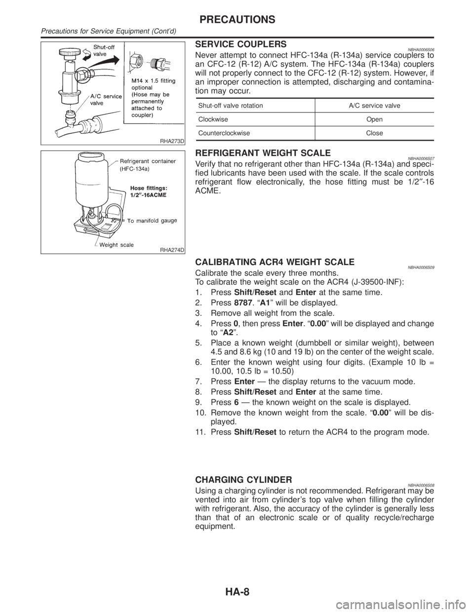
SERVICE COUPLERSNBHA0006S06Never attempt to connect HFC-134a (R-134a) service couplers to
an CFC-12 (R-12) A/C system. The HFC-134a (R-134a) couplers
will not properly connect to the CFC-12 (R-12) system. However, if
an improper connection is attempted, discharging and contamina-
tion may occur.
Shut-off valve rotation A/C service valve
Clockwise Open
Counterclockwise Close
RHA274D
REFRIGERANT WEIGHT SCALENBHA0006S07Verify that no refrigerant other than HFC-134a (R-134a) and speci-
fied lubricants have been used with the scale. If the scale controls
refrigerant flow electronically, the hose fitting must be 1/2²-16
ACME.
CALIBRATING ACR4 WEIGHT SCALENBHA0006S09Calibrate the scale every three months.
To calibrate the weight scale on the ACR4 (J-39500-INF):
1. PressShift/ResetandEnterat the same time.
2. Press8787.ªA1º will be displayed.
3. Remove all weight from the scale.
4. Press0, then pressEnter.ª0.00º will be displayed and change
to ªA2º.
5. Place a known weight (dumbbell or similar weight), between
4.5 and 8.6 kg (10 and 19 lb) on the center of the weight scale.
6. Enter the known weight using four digits. (Example 10 lb =
10.00, 10.5 lb = 10.50)
7. PressEnterÐ the display returns to the vacuum mode.
8. PressShift/ResetandEnterat the same time.
9. Press6Ð the known weight on the scale is displayed.
10. Remove the known weight from the scale. ª0.00º will be dis-
played.
11. PressShift/Resetto return the ACR4 to the program mode.
CHARGING CYLINDERNBHA0006S08Using a charging cylinder is not recommended. Refrigerant may be
vented into air from cylinder's top valve when filling the cylinder
with refrigerant. Also, the accuracy of the cylinder is generally less
than that of an electronic scale or of quality recycle/recharge
equipment.
PRECAUTIONS
Precautions for Service Equipment (Cont'd)
HA-8
Page 1812 of 2395
Tool number
(Kent-Moore No.)
Tool nameDescription
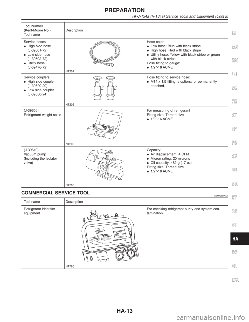
Service hoses
IHigh side hose
(J-39501-72)
ILow side hose
(J-39502-72)
IUtility hose
(J-39476-72)
NT201
Hose color:
ILow hose: Blue with black stripe
IHigh hose: Red with black stripe
IUtility hose: Yellow with black stripe or green
with black stripe
Hose fitting to gauge:
I1/2²-16 ACME
Service couplers
IHigh side coupler
(J-39500-20)
ILow side coupler
(J-39500-24)
NT202
Hose fitting to service hose:
IM14 x 1.5 fitting is optional or permanently
attached.
(J-39650)
Refrigerant weight scale
NT200
For measuring of refrigerant
Fitting size: Thread size
I1/2²-16 ACME
(J-39649)
Vacuum pump
(Including the isolator
valve)
NT203
Capacity:
IAir displacement: 4 CFM
IMicron rating: 20 microns
IOil capacity: 482 g (17 oz)
Fitting size: Thread size
I1/2²-16 ACME
COMMERCIAL SERVICE TOOLNBHA0009S01
Tool name Description
Refrigerant identifier
equipment
NT765
For checking refrigerant purity and system con-
tamination
GI
MA
EM
LC
EC
FE
AT
TF
PD
AX
SU
BR
ST
RS
BT
SC
EL
IDX
PREPARATION
HFC-134a (R-134a) Service Tools and Equipment (Cont'd)
HA-13
Page 1975 of 2395

SLC324B
SLC932A
SLC933A
SLC934AB
OIL PUMP INSPECTIONNBLC0007IInstall oil pump with the groove of the inner rotor facing
the oil pump cover.
Using a feeler gauge, straightedge and micrometers, check the
following clearances:
Unit: mm (in)
Body to outer rotor radial clearance 1 0.114 - 0.200 (0.0045 - 0.0079)
Inner rotor to outer gear tip clearance
2Below 0.18 (0.0071)
Body to inner rotor axial clearance 3 0.030 - 0.070 (0.0012 - 0.0028)
Body to outer rotor axial clearance 4 0.050 - 0.110 (0.0020 - 0.0043)
Inner rotor to brazed portion of hous-
ing clearance 50.045 - 0.091 (0.0018 - 0.0036)
IIf the tip clearance (2) exceeds the limit, replace rotor set.
IIf body to rotor clearances (1, 3, 4, 5) exceed the limit,
replace oil pump body assembly.
SLC251B
REGULATOR VALVE INSPECTIONNBLC00081. Visually inspect components for wear and damage.
2. Check oil pressure regulator valve sliding surface and valve
spring.
3. Coat regulator valve with engine oil. Check that it falls
smoothly into the valve hole by its own weight.
If damaged, replace regulator valve set or oil pump body.
ENGINE LUBRICATION SYSTEM
Oil Pump (Cont'd)
LC-6
Page 2226 of 2395
SFA449BA
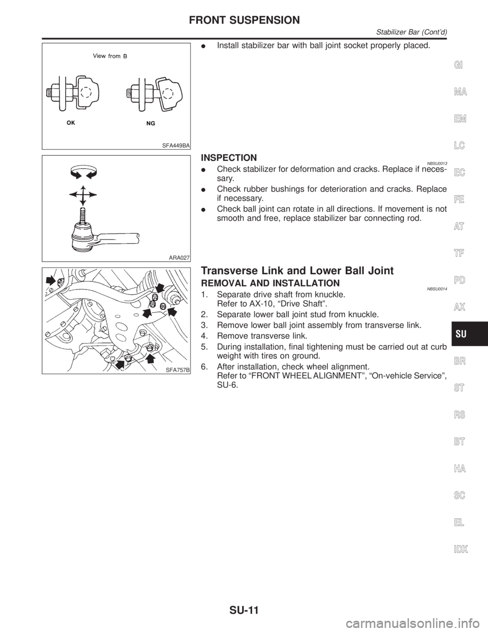
IInstall stabilizer bar with ball joint socket properly placed.
ARA027
INSPECTIONNBSU0013ICheck stabilizer for deformation and cracks. Replace if neces-
sary.
ICheck rubber bushings for deterioration and cracks. Replace
if necessary.
ICheck ball joint can rotate in all directions. If movement is not
smooth and free, replace stabilizer bar connecting rod.
SFA757B
Transverse Link and Lower Ball Joint
REMOVAL AND INSTALLATIONNBSU00141. Separate drive shaft from knuckle.
Refer to AX-10, ªDrive Shaftº.
2. Separate lower ball joint stud from knuckle.
3. Remove lower ball joint assembly from transverse link.
4. Remove transverse link.
5. During installation, final tightening must be carried out at curb
weight with tires on ground.
6. After installation, check wheel alignment.
Refer to ªFRONT WHEEL ALIGNMENTº, ªOn-vehicle Serviceº,
SU-6.
GI
MA
EM
LC
EC
FE
AT
TF
PD
AX
BR
ST
RS
BT
HA
SC
EL
IDX
FRONT SUSPENSION
Stabilizer Bar (Cont'd)
SU-11
Page 2239 of 2395

MEF040DB
IBefore replacing Transfer control unit, perform Transfer
control unit input/output signal inspection and make sure
whether Transfer control unit functions properly or not.
(See page TF-55.)
Service NoticeNBTF00021) Before proceeding with disassembly, thoroughly clean the outside of the all-mode 4WD transfer. It is
important to prevent the internal parts from becoming contaminated by dirt or other foreign matter.
2) Disassembly should be done in a clean work area.
3) Use lint-free cloth or towels for wiping parts clean. Common shop rags can leave fibers that could inter-
fere with the operation of the all-mode 4WD transfer.
4) Place disassembled parts in order for easier and proper assembly.
5) All parts should be carefully cleaned with a general purpose, non-flammable solvent before inspection or
reassembly.
6) Gaskets, seals and O-rings should be replaced any time the all-mode 4WD transfer is disassembled.
7) It is very important to perform functional tests whenever they are indicated.
8) The valve body contains precision parts and requires extreme care when parts are removed and serviced.
Place removed parts in a parts rack in order to replace them in correct positions and sequences. Care will
also prevent springs and small parts from becoming scattered or lost.
9) Properly installed valves, sleeves, plugs, etc. will slide along bores in valve body under their own weight.
10) Before assembly, apply a coat of recommended ATF to all parts. Apply petroleum jelly to protect O-rings
and seals, and to hold bearings and washers in place during assembly. Do not use grease.
11) Extreme care should be taken to avoid damage to O-rings, seals and gaskets when assembling.
12) After overhaul, refill the transfer with new ATF.
13) When the all-mode 4WD transfer drain plug is removed, only some of the fluid is drained. Old all-mode
4WD transfer fluid will remain in torque converter and ATF cooling system. Always follow the procedures,
MA-22, ªChanging All-mode 4WD Transfer Fluidº.
Wiring Diagrams and Trouble DiagnosisNBTF0003When you read wiring diagrams, refer to the following:
IGI-11, ªHOW TO READ WIRING DIAGRAMSº
IEL-9, ªPOWER SUPPLY ROUTINGº
When you perform trouble diagnosis, refer to the following:
IGI-35, ªHOW TO FOLLOW TEST GROUPS IN TROUBLE DIAGNOSISº
IGI-24, ªHOW TO PERFORM EFFICIENT DIAGNOSIS FOR AN ELECTRICAL INCIDENTº
PRECAUTIONS
Precautions (Cont'd)
TF-4