2001 INFINITI QX4 Ignition harness location
[x] Cancel search: Ignition harness locationPage 1751 of 2395

IClean all disassembled parts in the designated liquid or solvent
prior to inspection or assembly.
IReplace oil seals, gaskets, packings, O-rings, locking washers,
cotter pins, self-locking nuts, etc. with new ones.
IReplace inner and outer races of tapered roller bearings and
needle bearings as a set.
IArrange the disassembled parts in accordance with their
assembled locations and sequence.
IDo not touch the terminals of electrical components which use
microcomputers (such as ECMs).
Static electricity may damage internal electronic components.
IAfter disconnecting vacuum or air hoses, attach a tag to indi-
cate the proper connection.
IUse only the fluids and lubricants specified in this manual.
IUse approved bonding agent, sealants or their equivalents
when required.
IUse tools and recommended special tools where specified for
safe and efficient service repairs.
IWhen repairing the fuel, oil, water, vacuum or exhaust
systems, check all affected lines for leaks.
IDispose of drained oil or the solvent used for cleaning parts in
an appropriate manner.
WARNING:
To prevent ECM from storing the diagnostic trouble codes, do
not carelessly disconnect the harness connectors which are
related to the engine control system and TCM (Transmission
Control Module) system. The connectors should be discon-
nected only when working according to the WORK FLOW of
TROUBLE DIAGNOSES in EC and AT sections.
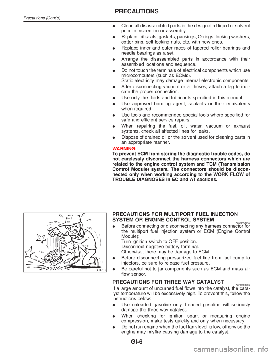
SGI787
PRECAUTIONS FOR MULTIPORT FUEL INJECTION
SYSTEM OR ENGINE CONTROL SYSTEM
NBGI0001S03IBefore connecting or disconnecting any harness connector for
the multiport fuel injection system or ECM (Engine Control
Module):
Turn ignition switch to OFF position.
Disconnect negative battery terminal.
Otherwise, there may be damage to ECM.
IBefore disconnecting pressurized fuel line from fuel pump to
injectors, be sure to release fuel pressure.
IBe careful not to jar components such as ECM and mass air
flow sensor.
PRECAUTIONS FOR THREE WAY CATALYSTNBGI0001S04If a large amount of unburned fuel flows into the catalyst, the cata-
lyst temperature will be excessively high. To prevent this, follow the
instructions below:
IUse unleaded gasoline only. Leaded gasoline will seriously
damage the three way catalyst.
IWhen checking for ignition spark or measuring engine
compression, make tests quickly and only when necessary.
IDo not run engine when the fuel tank level is low, otherwise the
engine may misfire causing damage to the catalyst.
PRECAUTIONS
Precautions (Cont'd)
GI-6
Page 1779 of 2395

NBGI0005
NOTICE:
Trouble diagnoses indicates work procedures required to diagnose
problems effectively. Observe the following instructions before
diagnosing.
1)Before performing trouble diagnoses, read the ªPrelimi-
nary Checkº, the ªSymptom Chartº or the ªWork Flowº.
2)After repairs, re-check that the problem has been com-
pletely eliminated.
3)Refer to Component Parts and Harness Connector Loca-
tion for the Systems described in each section for
identification/location of components and harness con-
nectors.
4)Refer to the Circuit Diagram for quick pinpoint check.
If you need to check circuit continuity between harness
connectors in more detail, such as when a sub-harness is
used, refer to Wiring Diagram in each individual section
and Harness Layout in EL section for identification of har-
ness connectors.
5)When checking circuit continuity, ignition switch should
be OFF.
6)Before checking voltage at connectors, check battery volt-
age.
7)After accomplishing the Diagnostic Procedures and Elec-
trical Components Inspection, make sure that all harness
connectors are reconnected as they were.
HOW TO FOLLOW TROUBLE DIAGNOSIS
GI-34
Page 1964 of 2395

Fusible link ......................................................EL-16
G
Garage jack and safety stand .........................GI-46
Gauges............................................................EL-94
Generator - See Alternator .............................SC-28
Generic scan tool (GST) ................................EC-95
Glass ...............................................................BT-18
Glass hatch opener, electric .........................EL-178
Grease ............................................................MA-11
Ground distribution..........................................EL-17
H
Harness connector ............................................EL-5
Harness connector inspection .........................GI-21
Harness layout ..............................................EL-440
Hazard warning lamp ......................................EL-75
Headlamp ........................................................EL-31
Headlamp aiming control ................................EL-59
Headlining - See Roof trim .............................BT-32
Heated seat .......................................BT-43, EL-183
Height (Dimensions) ........................................GI-43
HFC134a (R134a) system precaution .............HA-2
HFC134a (R134a) system service
procedure ..................................................HA-144
HFC134a (R134a) system service tools ........HA-11
HFC134a system service equipment
precaution .....................................................HA-7
High clutch.....................................................AT-317
H/LAMP - Wiring diagram ...............................EL-36
Hood................................................................BT-12
Horn ..............................................................EL-147
HORN - Wiring diagram................................EL-147
How to erase DTC for OBD system...............EC-72
HSEAT - Wiring diagram...............................EL-183
I
IACV-AAC valve ...........................................EC-422
IATS - Wiring diagram ..................................EC-166
Identification .....................................................HA-4
Identification plate............................................GI-42
Idle air control valve (IACV) .........................EC-422
Idle mixture ratio.............................................EC-43
Idle speed .......................................................EC-43
IGN/SG - Wiring diagram .............................EC-501
Ignition control system .................................EC-499
Ignition timing .................................................EC-43
ILL - Wiring diagram .......................................EL-83
Illumination ......................................................EL-80
In vehicle sensor ..........................................HA-132
INFINITI COMMUNICATOR..........................EL-348
Infiniti communicator (IVCS) .........................EL-348
INJECT - Wiring diagram .............................EC-617
Injector ..........................................................EC-616Injector removal and installation ....................EC-41
Instrument panel .............................................BT-21
INT/L - Wiring diagram....................................EL-91
Intake air temparature sensor ......................EC-164
Intake door control linkage adjustment ..........HA-94
Intake door motor ...........................................HA-87
Intake manifold...............................................EM-12
Intake sensor ................................................HA-139
Integrated homelink transmitter ....................EL-325
Interior .............................................................BT-28
Interior lamp ....................................................EL-88
Interior lamp on-off control ..............................EL-89
Internal gear (Transfer) .................................TF-134
IVC-L - Wiring diagram.................................EC-453
IVC-R - Wiring diagram ................................EC-453
IVCS - Wiring diagram ..................................EL-359
IVCS-L - Wiring diagram ..............................EC-485
IVCS-R - Wiring diagram .............................EC-485
IVIS (Infiniti vehicle immobilizer
system) ......................................................EL-328
IVIS (Infiniti vehicle immobilizer sys-
tem) precautions ............................................GI-3
J
Jacking points ..................................................GI-45
Journal bearing assembly (propeller
shaft) .............................................................PD-9
Journal bearing disassembly (propeller
shaft) .............................................................PD-8
Junction box (J/B).........................................Foldout
K
Keyless entry system - See Multi-re-
mote control system ..................................EL-270
Knock sensor (KS) .......................................EC-328
Knuckle spindle ................................................AX-9
KS - Wiring diagram .....................................EC-330
L
Length (Dimensions) .......................................GI-43
License lamp ...................................................EL-61
Lifting points ....................................................GI-47
Limited slip diff. adjustment ............................PD-50
Limited slip diff. assembly ..............................PD-51
Limited slip diff. disassembly..........................PD-48
Limited slip diff. inspection .............................PD-49
Line pressure solenoid valve ........AT-147, 161, 167
Line pressure switch (Transfer) .....................TF-111
Line pressure test (A/T) ..................................AT-62
Liquid gasket application .................................EM-3
LOAD - Wiring diagram ................................EC-643
Location of electrical units ............................EL-436
Lock, door .......................................................BT-18
Low and reverse brake .................................AT-324
GI
MA
EM
LC
EC
FE
AT
TF
PD
AX
SU
BR
ST
RS
BT
HA
SC
EL
ALPHABETICAL INDEX
IDX-5