2001 INFINITI QX4 IDX
[x] Cancel search: IDXPage 2212 of 2395
SST933C
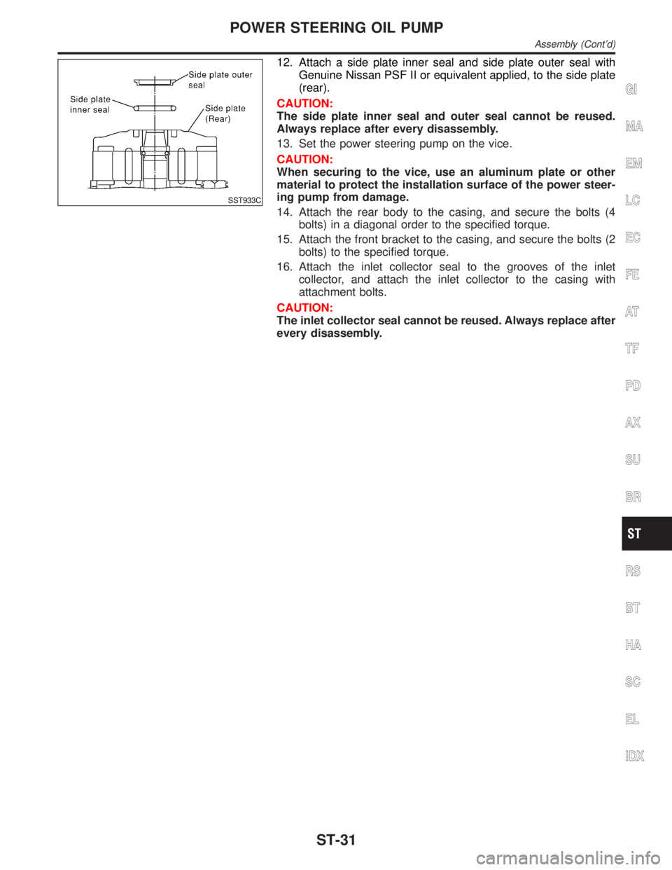
12. Attach a side plate inner seal and side plate outer seal with
Genuine Nissan PSF II or equivalent applied, to the side plate
(rear).
CAUTION:
The side plate inner seal and outer seal cannot be reused.
Always replace after every disassembly.
13. Set the power steering pump on the vice.
CAUTION:
When securing to the vice, use an aluminum plate or other
material to protect the installation surface of the power steer-
ing pump from damage.
14. Attach the rear body to the casing, and secure the bolts (4
bolts) in a diagonal order to the specified torque.
15. Attach the front bracket to the casing, and secure the bolts (2
bolts) to the specified torque.
16. Attach the inlet collector seal to the grooves of the inlet
collector, and attach the inlet collector to the casing with
attachment bolts.
CAUTION:
The inlet collector seal cannot be reused. Always replace after
every disassembly.
GI
MA
EM
LC
EC
FE
AT
TF
PD
AX
SU
BR
RS
BT
HA
SC
EL
IDX
POWER STEERING OIL PUMP
Assembly (Cont'd)
ST-31
Page 2214 of 2395
Steering Gear and LinkageNBST0040
Applied modelAll
Steering gear typePR32K
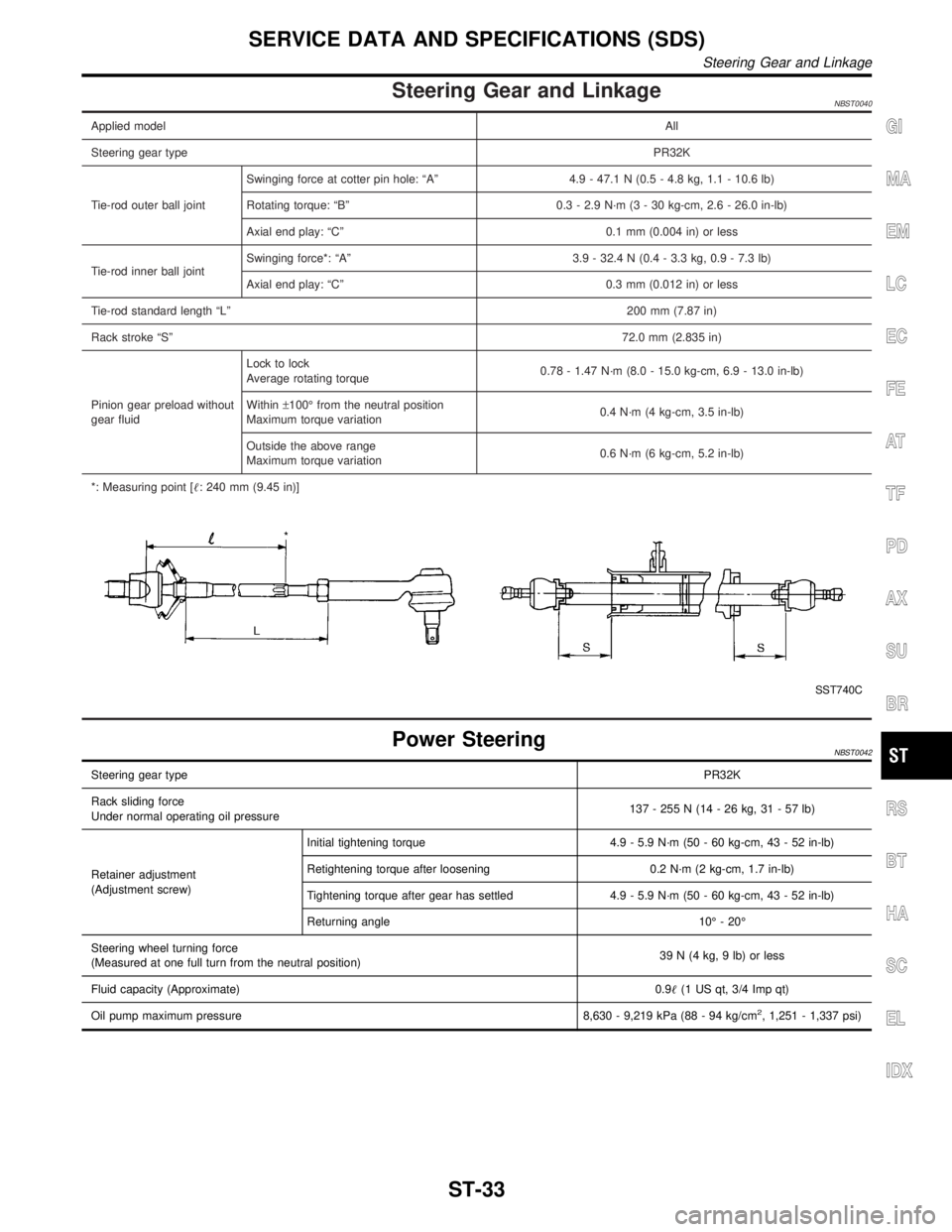
Tie-rod outer ball jointSwinging force at cotter pin hole: ªAº 4.9 - 47.1 N (0.5 - 4.8 kg, 1.1 - 10.6 lb)
Rotating torque: ªBº 0.3 - 2.9 N´m (3 - 30 kg-cm, 2.6 - 26.0 in-lb)
Axial end play: ªCº 0.1 mm (0.004 in) or less
Tie-rod inner ball jointSwinging force*: ªAº 3.9 - 32.4 N (0.4 - 3.3 kg, 0.9 - 7.3 lb)
Axial end play: ªCº 0.3 mm (0.012 in) or less
Tie-rod standard length ªLº200 mm (7.87 in)
Rack stroke ªSº72.0 mm (2.835 in)
Pinion gear preload without
gear fluidLock to lock
Average rotating torque0.78 - 1.47 N´m (8.0 - 15.0 kg-cm, 6.9 - 13.0 in-lb)
Within±100É from the neutral position
Maximum torque variation0.4 N´m (4 kg-cm, 3.5 in-lb)
Outside the above range
Maximum torque variation0.6 N´m (6 kg-cm, 5.2 in-lb)
*: Measuring point [: 240 mm (9.45 in)]
SST740C
Power SteeringNBST0042
Steering gear typePR32K
Rack sliding force
Under normal operating oil pressure137 - 255 N (14 - 26 kg, 31 - 57 lb)
Retainer adjustment
(Adjustment screw)Initial tightening torque 4.9 - 5.9 N´m (50 - 60 kg-cm, 43 - 52 in-lb)
Retightening torque after loosening 0.2 N´m (2 kg-cm, 1.7 in-lb)
Tightening torque after gear has settled 4.9 - 5.9 N´m (50 - 60 kg-cm, 43 - 52 in-lb)
Returning angle 10É - 20É
Steering wheel turning force
(Measured at one full turn from the neutral position)39 N (4 kg, 9 lb) or less
Fluid capacity (Approximate)0.9(1 US qt, 3/4 Imp qt)
Oil pump maximum pressure 8,630 - 9,219 kPa (88 - 94 kg/cm
2, 1,251 - 1,337 psi)
GI
MA
EM
LC
EC
FE
AT
TF
PD
AX
SU
BR
RS
BT
HA
SC
EL
IDX
SERVICE DATA AND SPECIFICATIONS (SDS)
Steering Gear and Linkage
ST-33
Page 2216 of 2395
FRONT & REAR SUSPENSION
SECTION
SU
CONTENTS
FRONT SUSPENSION....................................................2
Precautions ..................................................................2
PRECAUTIONS.........................................................2
Preparation ..................................................................2
SPECIAL SERVICE TOOLS........................................2
COMMERCIAL SERVICE TOOLS................................2
Noise, Vibration and Harshness (NVH)
Troubleshooting ...........................................................3
NVH TROUBLESHOOTING CHART............................3
Components.................................................................4
On-vehicle Service.......................................................5
FRONT SUSPENSION PARTS...................................5
FRONT WHEEL ALIGNMENT.....................................6
Coil Spring and Strut Assembly...................................8
COMPONENTS.........................................................8
REMOVAL.................................................................9
DISASSEMBLY..........................................................9
INSPECTION.............................................................9
ASSEMBLY.............................................................10
Stabilizer Bar .............................................................10
REMOVAL AND INSTALLATION...............................10
INSPECTION........................................................... 11
Transverse Link and Lower Ball Joint ....................... 11
REMOVAL AND INSTALLATION............................... 11
INSPECTION...........................................................12
Service Data and Specifications (SDS).....................13
GENERAL SPECIFICATIONS (FRONT).....................13
WHEEL ALIGNMENT (UNLADEN*1)..........................13
LOWER BALL JOINT...............................................13
WHEELARCH HEIGHT (UNLADEN*).........................14
WHEEL RUNOUT AVERAGE*..................................14
REAR SUSPENSION.....................................................15
Precautions ................................................................15
PRECAUTIONS.......................................................15
Preparation ................................................................15
COMMERCIAL SERVICE TOOLS..............................15
Noise, Vibration and Harshness (NVH)
Troubleshooting .........................................................15
Components...............................................................16
On-vehicle Service.....................................................16
REAR SUSPENSION PARTS...................................16
Removal and Installation ...........................................17
Coil Spring and Shock Absorber ...............................18
COMPONENTS.......................................................18
REMOVAL AND INSTALLATION...............................19
INSPECTION...........................................................19
Upper Link, Lower Link and Panhard Rod ................19
INSPECTION...........................................................19
BUSHING REPLACEMENT.......................................19
INSTALLATION........................................................20
Stabilizer Bar .............................................................20
REMOVAL AND INSTALLATION...............................20
Service Data and Specifications (SDS).....................20
GENERAL SPECIFICATIONS (REAR).......................20
GI
MA
EM
LC
EC
FE
AT
TF
PD
AX
BR
ST
RS
BT
HA
SC
EL
IDX
Page 2218 of 2395
Noise, Vibration and Harshness (NVH)
Troubleshooting
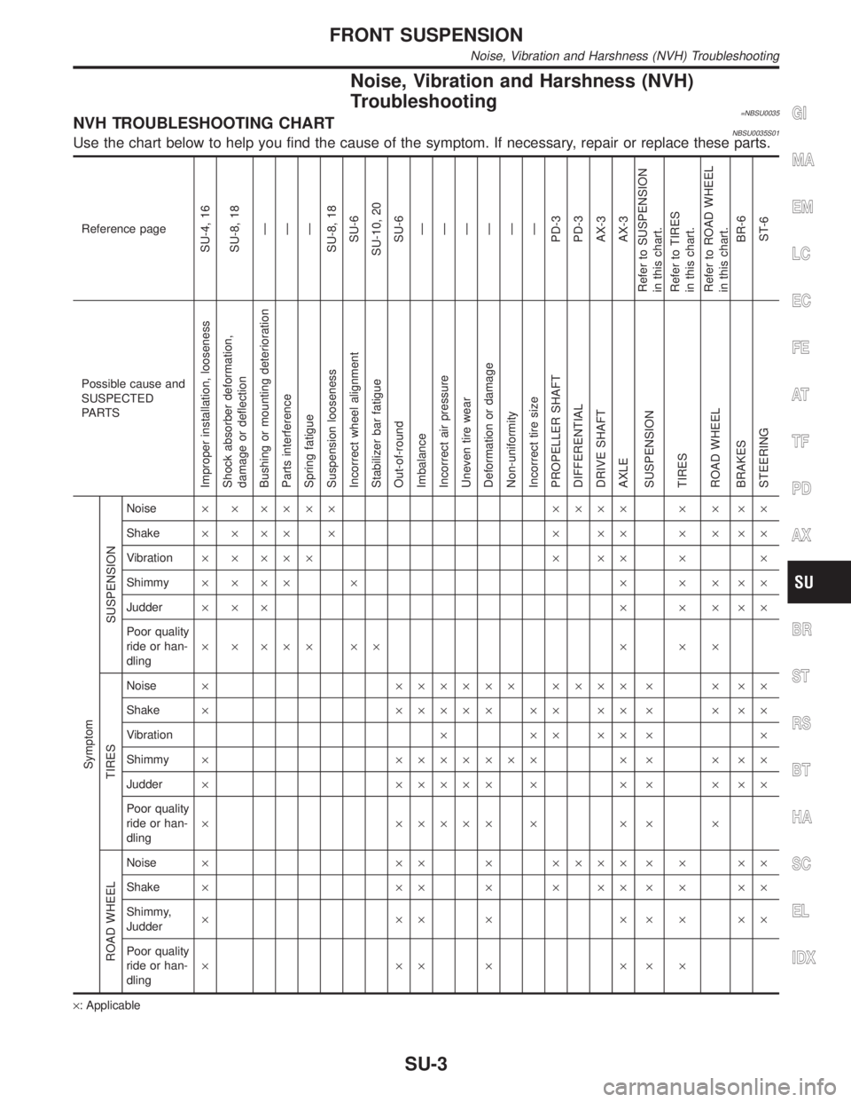
=NBSU0035NVH TROUBLESHOOTING CHARTNBSU0035S01Use the chart below to help you find the cause of the symptom. If necessary, repair or replace these parts.
Reference page
SU-4, 16
SU-8, 18
Ð
Ð
Ð
SU-8, 18
SU-6
SU-10, 20
SU-6
Ð
Ð
Ð
Ð
Ð
Ð
PD-3
PD-3
AX-3
AX-3
Refer to SUSPENSION
in this chart.
Refer to TIRES
in this chart.
Refer to ROAD WHEEL
in this chart.
BR-6
ST-6
Possible cause and
SUSPECTED
PA R T S
Improper installation, looseness
Shock absorber deformation,
damage or deflection
Bushing or mounting deterioration
Parts interference
Spring fatigue
Suspension looseness
Incorrect wheel alignment
Stabilizer bar fatigue
Out-of-round
Imbalance
Incorrect air pressure
Uneven tire wear
Deformation or damage
Non-uniformity
Incorrect tire size
PROPELLER SHAFT
DIFFERENTIAL
DRIVE SHAFT
AXLE
SUSPENSION
TIRES
ROAD WHEEL
BRAKES
STEERING Symptom
SUSPENSION
Noise´ ´ ´´´´ ´´´´ ´ ´ ´´
Shake´´´´´ ´´´ ´´´´
Vibration´ ´ ´´´ ´ ´´ ´ ´
Shimmy´´´´ ´ ´ ´ ´´´
Judder´´´ ´ ´ ´´´
Poor quality
ride or han-
dling´ ´ ´´´ ´´ ´ ´ ´
TIRES
Noise´ ´´´´´´ ´´´´ ´ ´ ´´
Shake´ ´´´´´ ´´ ´´ ´ ´ ´´
Vibration´´´´´´ ´
Shimmy´ ´´´´´´´ ´ ´ ´ ´´
Judder´ ´´´´´ ´ ´ ´ ´ ´´
Poor quality
ride or han-
dling´ ´´´´´ ´ ´ ´ ´
ROAD WHEEL
Noise´ ´´ ´ ´´´´ ´ ´ ´´
Shake´ ´´ ´ ´ ´´ ´ ´ ´´
Shimmy,
Judder´´´´´´´´´
Poor quality
ride or han-
dling´´´´´´´
´: Applicable
GI
MA
EM
LC
EC
FE
AT
TF
PD
AX
BR
ST
RS
BT
HA
SC
EL
IDX
FRONT SUSPENSION
Noise, Vibration and Harshness (NVH) Troubleshooting
SU-3
Page 2220 of 2395
SMA525A
On-vehicle Service
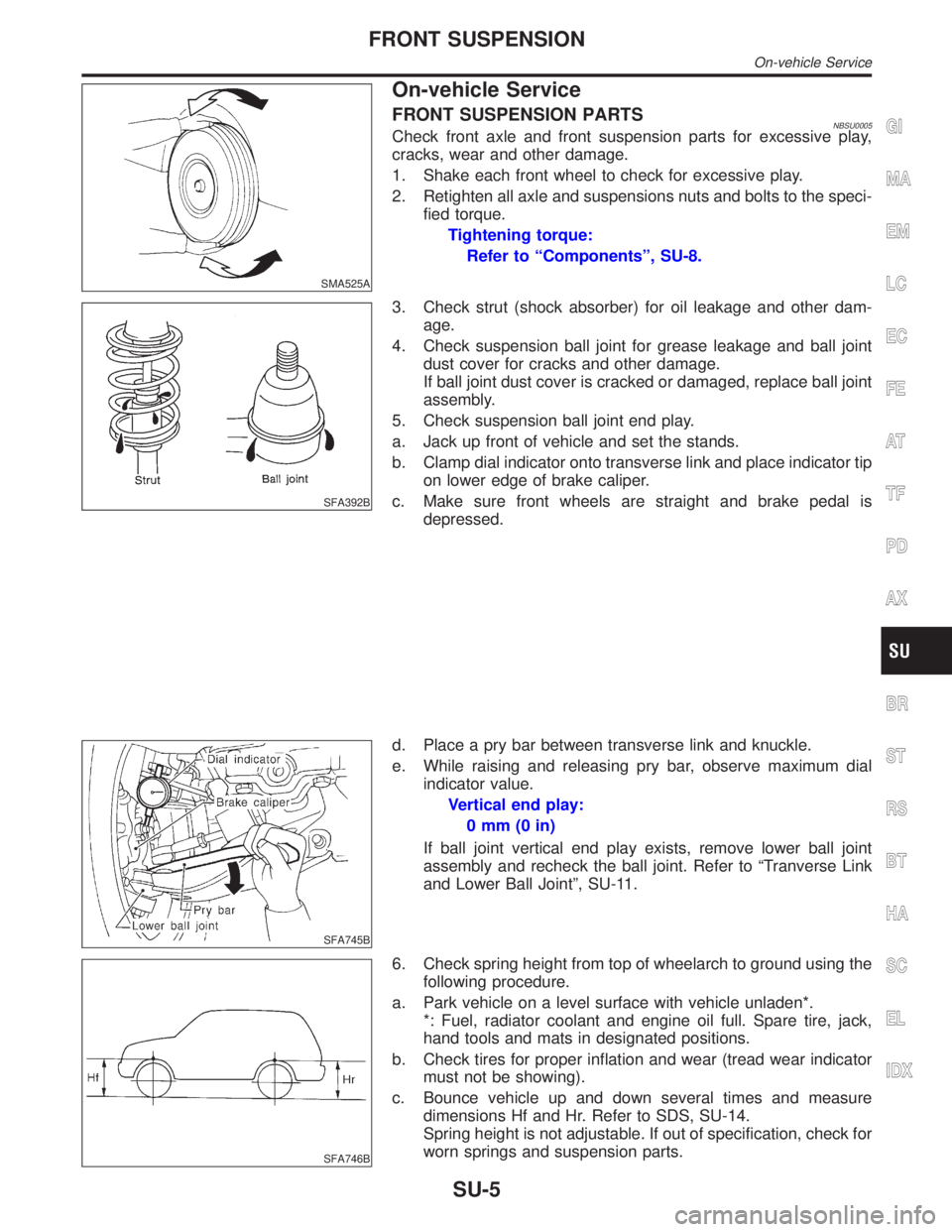
FRONT SUSPENSION PARTSNBSU0005Check front axle and front suspension parts for excessive play,
cracks, wear and other damage.
1. Shake each front wheel to check for excessive play.
2. Retighten all axle and suspensions nuts and bolts to the speci-
fied torque.
Tightening torque:
Refer to ªComponentsº, SU-8.
SFA392B
3. Check strut (shock absorber) for oil leakage and other dam-
age.
4. Check suspension ball joint for grease leakage and ball joint
dust cover for cracks and other damage.
If ball joint dust cover is cracked or damaged, replace ball joint
assembly.
5. Check suspension ball joint end play.
a. Jack up front of vehicle and set the stands.
b. Clamp dial indicator onto transverse link and place indicator tip
on lower edge of brake caliper.
c. Make sure front wheels are straight and brake pedal is
depressed.
SFA745B
d. Place a pry bar between transverse link and knuckle.
e. While raising and releasing pry bar, observe maximum dial
indicator value.
Vertical end play:
0mm(0in)
If ball joint vertical end play exists, remove lower ball joint
assembly and recheck the ball joint. Refer to ªTranverse Link
and Lower Ball Jointº, SU-11.
SFA746B
6. Check spring height from top of wheelarch to ground using the
following procedure.
a. Park vehicle on a level surface with vehicle unladen*.
*: Fuel, radiator coolant and engine oil full. Spare tire, jack,
hand tools and mats in designated positions.
b. Check tires for proper inflation and wear (tread wear indicator
must not be showing).
c. Bounce vehicle up and down several times and measure
dimensions Hf and Hr. Refer to SDS, SU-14.
Spring height is not adjustable. If out of specification, check for
worn springs and suspension parts.
GI
MA
EM
LC
EC
FE
AT
TF
PD
AX
BR
ST
RS
BT
HA
SC
EL
IDX
FRONT SUSPENSION
On-vehicle Service
SU-5
Page 2222 of 2395
SFA614B
SFA234AC
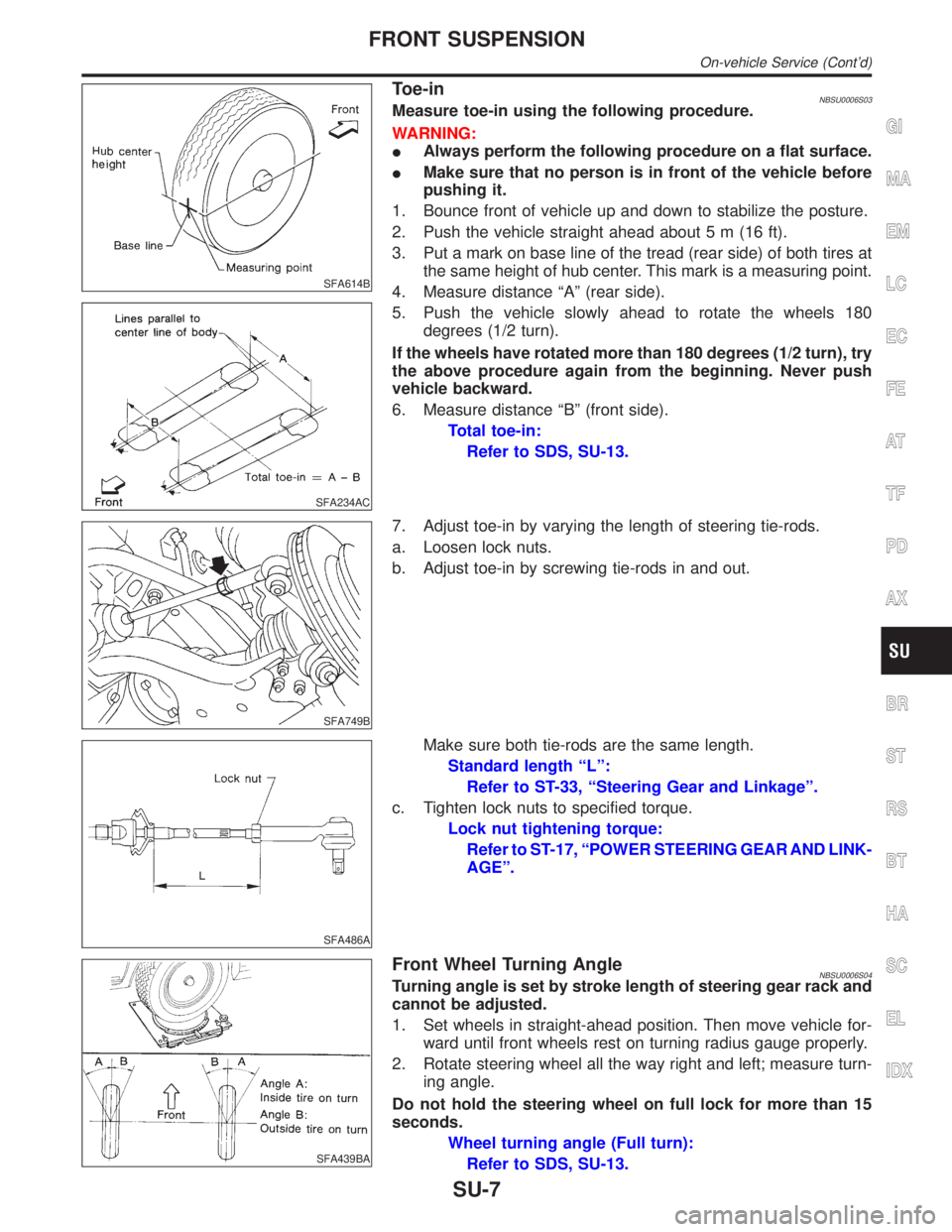
Toe-inNBSU0006S03Measure toe-in using the following procedure.
WARNING:
IAlways perform the following procedure on a flat surface.
IMake sure that no person is in front of the vehicle before
pushing it.
1. Bounce front of vehicle up and down to stabilize the posture.
2. Push the vehicle straight ahead about 5 m (16 ft).
3. Put a mark on base line of the tread (rear side) of both tires at
the same height of hub center. This mark is a measuring point.
4. Measure distance ªAº (rear side).
5. Push the vehicle slowly ahead to rotate the wheels 180
degrees (1/2 turn).
If the wheels have rotated more than 180 degrees (1/2 turn), try
the above procedure again from the beginning. Never push
vehicle backward.
6. Measure distance ªBº (front side).
Total toe-in:
Refer to SDS, SU-13.
SFA749B
7. Adjust toe-in by varying the length of steering tie-rods.
a. Loosen lock nuts.
b. Adjust toe-in by screwing tie-rods in and out.
SFA486A
Make sure both tie-rods are the same length.
Standard length ªLº:
Refer to ST-33, ªSteering Gear and Linkageº.
c. Tighten lock nuts to specified torque.
Lock nut tightening torque:
Refer to ST-17, ªPOWER STEERING GEAR AND LINK-
AGEº.
SFA439BA
Front Wheel Turning AngleNBSU0006S04Turning angle is set by stroke length of steering gear rack and
cannot be adjusted.
1. Set wheels in straight-ahead position. Then move vehicle for-
ward until front wheels rest on turning radius gauge properly.
2. Rotate steering wheel all the way right and left; measure turn-
ing angle.
Do not hold the steering wheel on full lock for more than 15
seconds.
Wheel turning angle (Full turn):
Refer to SDS, SU-13.
GI
MA
EM
LC
EC
FE
AT
TF
PD
AX
BR
ST
RS
BT
HA
SC
EL
IDX
FRONT SUSPENSION
On-vehicle Service (Cont'd)
SU-7
Page 2224 of 2395
SFA956A
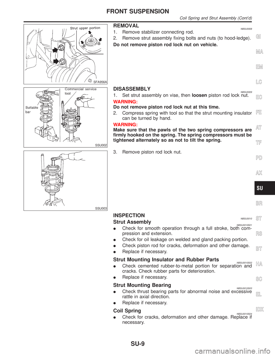
REMOVALNBSU00081. Remove stabilizer connecting rod.
2. Remove strut assembly fixing bolts and nuts (to hood-ledge).
Do not remove piston rod lock nut on vehicle.
SSU002
DISASSEMBLYNBSU00091. Set strut assembly on vise, thenloosenpiston rod lock nut.
WARNING:
Do not remove piston rod lock nut at this time.
2. Compress spring with tool so that the strut mounting insulator
can be turned by hand.
WARNING:
Make sure that the pawls of the two spring compressors are
firmly hooked on the spring. The spring compressors must be
tightened alternately so as not to tilt the spring.
SSU003
3. Remove piston rod lock nut.
INSPECTIONNBSU0010Strut AssemblyNBSU0010S01ICheck for smooth operation through a full stroke, both com-
pression and extension.
ICheck for oil leakage on welded and gland packing portion.
ICheck piston rod for cracks, deformation and other damage.
IReplace if necessary.
Strut Mounting Insulator and Rubber PartsNBSU0010S02ICheck cemented rubber-to-metal portion for separation and
cracks. Check rubber parts for deterioration.
IReplace if necessary.
Strut Mounting BearingNBSU0010S03ICheck thrust bearing parts for abnormal noise and excessive
rattle in axial direction.
IReplace if necessary.
Coil SpringNBSU0010S04ICheck for cracks, deformation and other damage. Replace if
necessary.
GI
MA
EM
LC
EC
FE
AT
TF
PD
AX
BR
ST
RS
BT
HA
SC
EL
IDX
FRONT SUSPENSION
Coil Spring and Strut Assembly (Cont'd)
SU-9
Page 2226 of 2395
SFA449BA
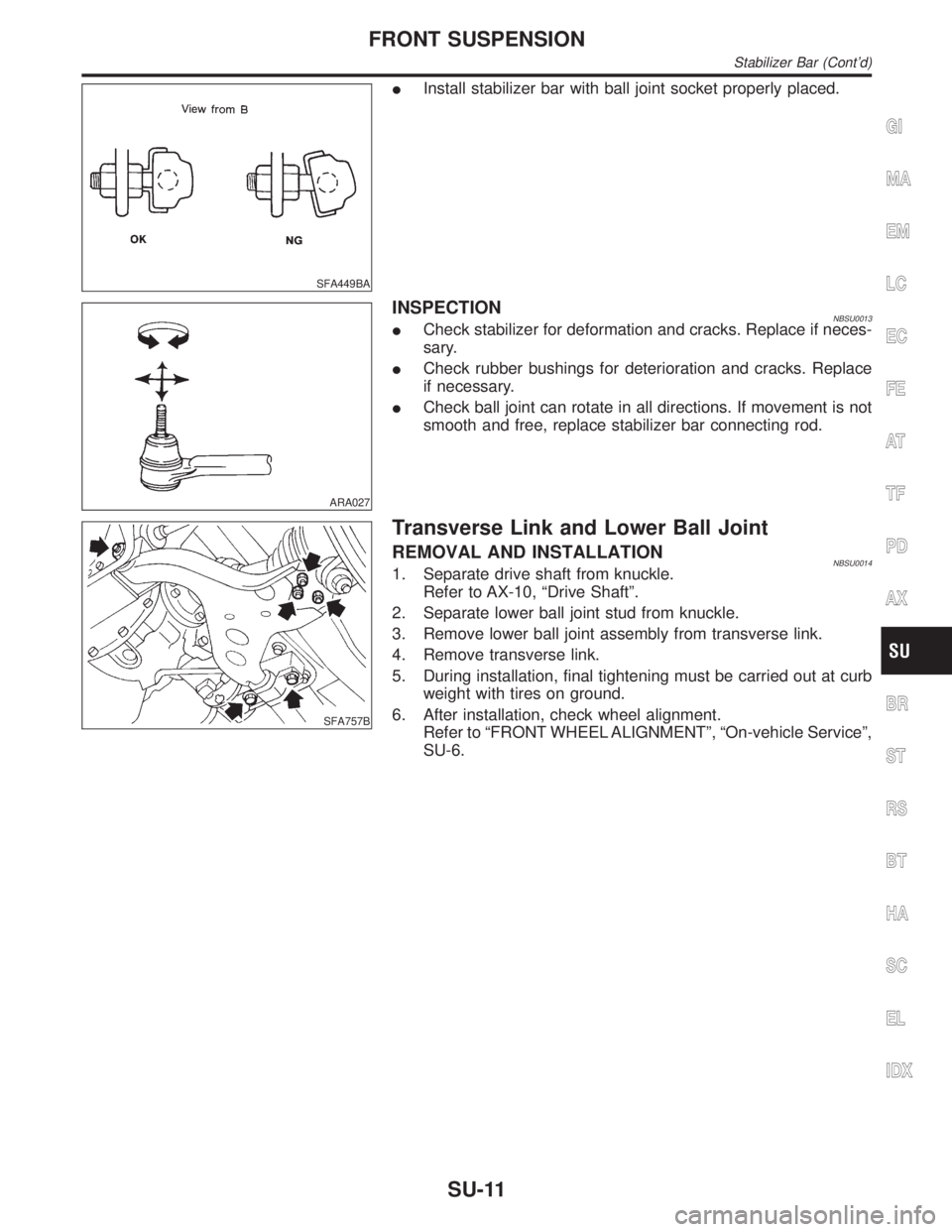
IInstall stabilizer bar with ball joint socket properly placed.
ARA027
INSPECTIONNBSU0013ICheck stabilizer for deformation and cracks. Replace if neces-
sary.
ICheck rubber bushings for deterioration and cracks. Replace
if necessary.
ICheck ball joint can rotate in all directions. If movement is not
smooth and free, replace stabilizer bar connecting rod.
SFA757B
Transverse Link and Lower Ball Joint
REMOVAL AND INSTALLATIONNBSU00141. Separate drive shaft from knuckle.
Refer to AX-10, ªDrive Shaftº.
2. Separate lower ball joint stud from knuckle.
3. Remove lower ball joint assembly from transverse link.
4. Remove transverse link.
5. During installation, final tightening must be carried out at curb
weight with tires on ground.
6. After installation, check wheel alignment.
Refer to ªFRONT WHEEL ALIGNMENTº, ªOn-vehicle Serviceº,
SU-6.
GI
MA
EM
LC
EC
FE
AT
TF
PD
AX
BR
ST
RS
BT
HA
SC
EL
IDX
FRONT SUSPENSION
Stabilizer Bar (Cont'd)
SU-11