2001 INFINITI QX4 IDX
[x] Cancel search: IDXPage 2228 of 2395
Service Data and Specifications (SDS)
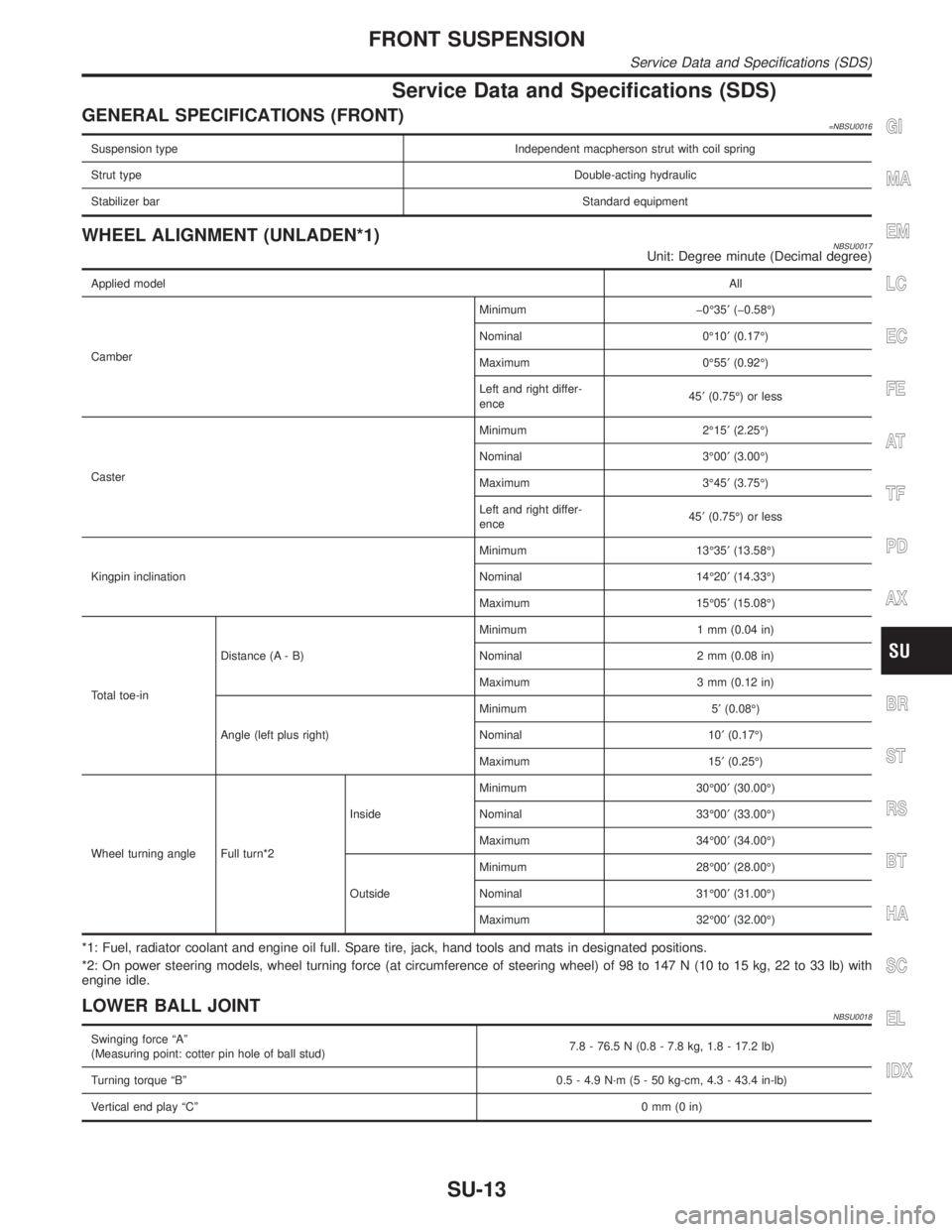
GENERAL SPECIFICATIONS (FRONT)=NBSU0016
Suspension type Independent macpherson strut with coil spring
Strut typeDouble-acting hydraulic
Stabilizer barStandard equipment
WHEEL ALIGNMENT (UNLADEN*1)NBSU0017Unit: Degree minute (Decimal degree)
Applied modelAll
CamberMinimum þ0É35¢(þ0.58É)
Nominal 0É10¢(0.17É)
Maximum 0É55¢(0.92É)
Left and right differ-
ence45¢(0.75É) or less
CasterMinimum 2É15¢(2.25É)
Nominal 3É00¢(3.00É)
Maximum 3É45¢(3.75É)
Left and right differ-
ence45¢(0.75É) or less
Kingpin inclinationMinimum 13É35¢(13.58É)
Nominal 14É20¢(14.33É)
Maximum 15É05¢(15.08É)
Total toe-inDistance (A - B)Minimum 1 mm (0.04 in)
Nominal 2 mm (0.08 in)
Maximum 3 mm (0.12 in)
Angle (left plus right)Minimum 5¢(0.08É)
Nominal 10¢(0.17É)
Maximum 15¢(0.25É)
Wheel turning angle Full turn*2InsideMinimum 30É00¢(30.00É)
Nominal 33É00¢(33.00É)
Maximum 34É00¢(34.00É)
OutsideMinimum 28É00¢(28.00É)
Nominal 31É00¢(31.00É)
Maximum 32É00¢(32.00É)
*1: Fuel, radiator coolant and engine oil full. Spare tire, jack, hand tools and mats in designated positions.
*2: On power steering models, wheel turning force (at circumference of steering wheel) of 98 to 147 N (10 to 15 kg, 22 to 33 lb) with
engine idle.
LOWER BALL JOINTNBSU0018
Swinging force ªAº
(Measuring point: cotter pin hole of ball stud)7.8 - 76.5 N (0.8 - 7.8 kg, 1.8 - 17.2 lb)
Turning torque ªBº 0.5 - 4.9 N´m (5 - 50 kg-cm, 4.3 - 43.4 in-lb)
Vertical end play ªCº0mm(0in)
GI
MA
EM
LC
EC
FE
AT
TF
PD
AX
BR
ST
RS
BT
HA
SC
EL
IDX
FRONT SUSPENSION
Service Data and Specifications (SDS)
SU-13
Page 2230 of 2395
SBR686C
Precautions
PRECAUTIONSNBSU0021IWhen installing rubber parts, final tightening must be car-
ried out under unladen condition* with tires on ground.
*Fuel, radiator coolant and engine oil full. Spare tire, jack,
hand tools and mats in designated positions.
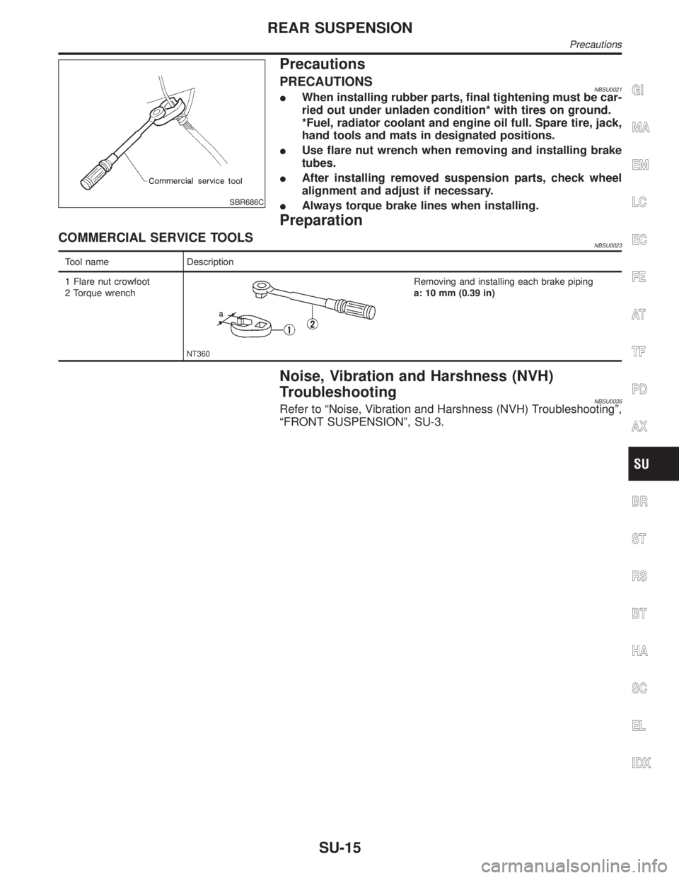
IUse flare nut wrench when removing and installing brake
tubes.
IAfter installing removed suspension parts, check wheel
alignment and adjust if necessary.
IAlways torque brake lines when installing.
Preparation
COMMERCIAL SERVICE TOOLSNBSU0023
Tool name Description
1 Flare nut crowfoot
2 Torque wrench
NT360
Removing and installing each brake piping
a: 10 mm (0.39 in)
Noise, Vibration and Harshness (NVH)
Troubleshooting
NBSU0036Refer to ªNoise, Vibration and Harshness (NVH) Troubleshootingº,
ªFRONT SUSPENSIONº, SU-3.
GI
MA
EM
LC
EC
FE
AT
TF
PD
AX
BR
ST
RS
BT
HA
SC
EL
IDX
REAR SUSPENSION
Precautions
SU-15
Page 2232 of 2395
SBR686C
Removal and InstallationNBSU00261. Support axle and suspension components with a suitable jack
and block.
2. Disconnect brake hydraulic line and parking brake cables at
back plates.
CAUTION:
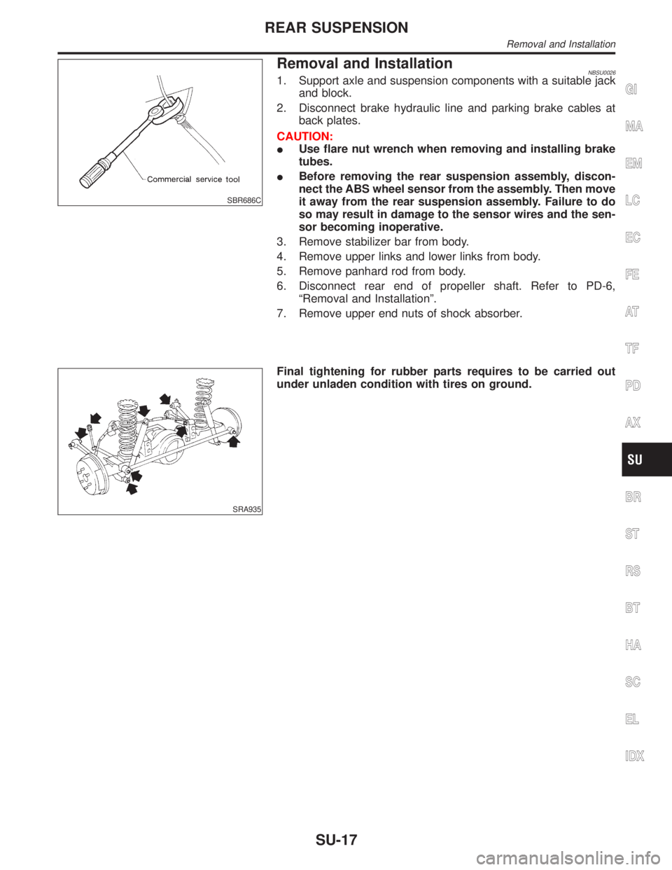
IUse flare nut wrench when removing and installing brake
tubes.
IBefore removing the rear suspension assembly, discon-
nect the ABS wheel sensor from the assembly. Then move
it away from the rear suspension assembly. Failure to do
so may result in damage to the sensor wires and the sen-
sor becoming inoperative.
3. Remove stabilizer bar from body.
4. Remove upper links and lower links from body.
5. Remove panhard rod from body.
6. Disconnect rear end of propeller shaft. Refer to PD-6,
ªRemoval and Installationº.
7. Remove upper end nuts of shock absorber.
SRA935
Final tightening for rubber parts requires to be carried out
under unladen condition with tires on ground.
GI
MA
EM
LC
EC
FE
AT
TF
PD
AX
BR
ST
RS
BT
HA
SC
EL
IDX
REAR SUSPENSION
Removal and Installation
SU-17
Page 2234 of 2395
SRA645A
REMOVAL AND INSTALLATIONNBSU0028Refer to ªRemoval and Installationº, ªREAR SUSPENSIONº,
SU-17.
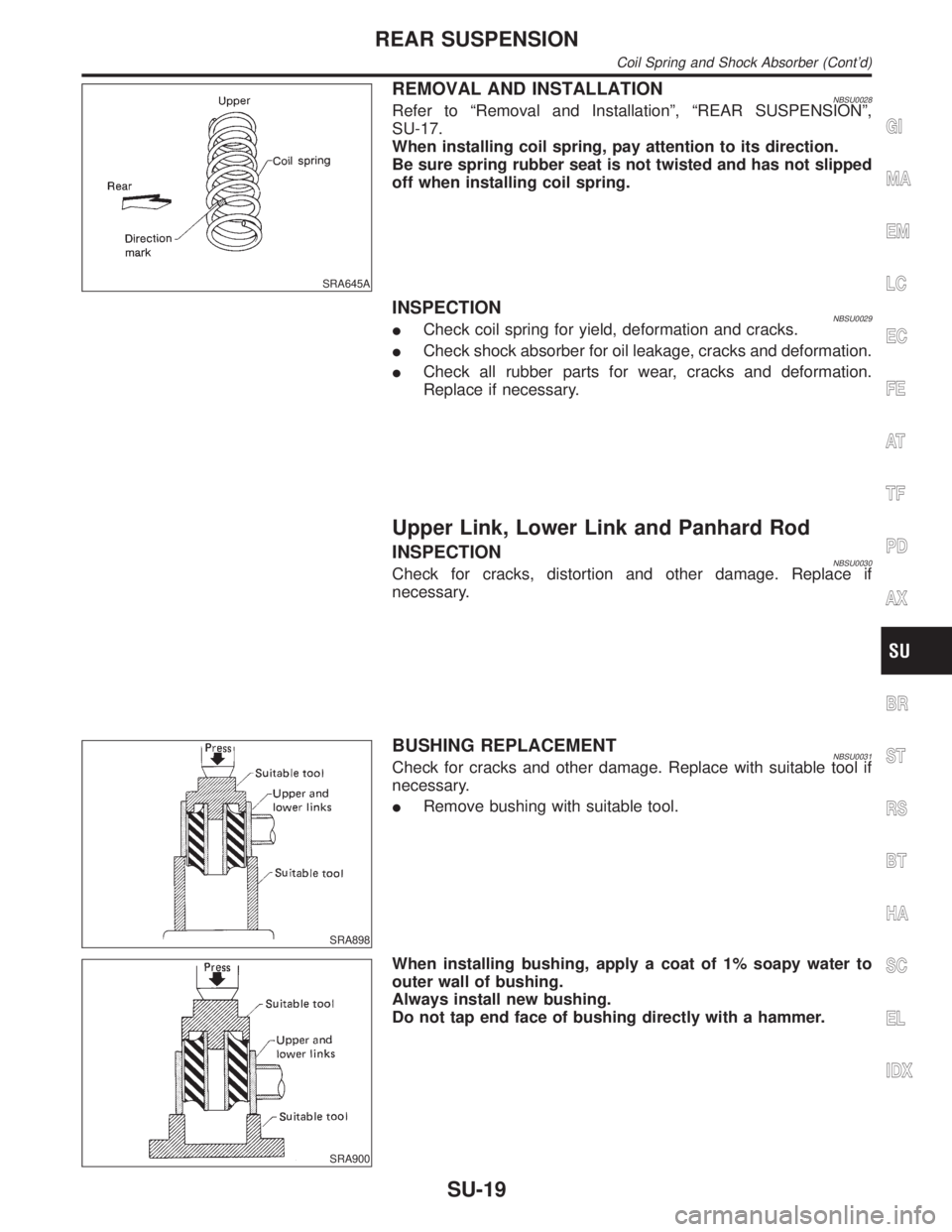
When installing coil spring, pay attention to its direction.
Be sure spring rubber seat is not twisted and has not slipped
off when installing coil spring.
INSPECTIONNBSU0029ICheck coil spring for yield, deformation and cracks.
ICheck shock absorber for oil leakage, cracks and deformation.
ICheck all rubber parts for wear, cracks and deformation.
Replace if necessary.
Upper Link, Lower Link and Panhard Rod
INSPECTIONNBSU0030Check for cracks, distortion and other damage. Replace if
necessary.
SRA898
BUSHING REPLACEMENTNBSU0031Check for cracks and other damage. Replace with suitable tool if
necessary.
IRemove bushing with suitable tool.
SRA900
When installing bushing, apply a coat of 1% soapy water to
outer wall of bushing.
Always install new bushing.
Do not tap end face of bushing directly with a hammer.
GI
MA
EM
LC
EC
FE
AT
TF
PD
AX
BR
ST
RS
BT
HA
SC
EL
IDX
REAR SUSPENSION
Coil Spring and Shock Absorber (Cont'd)
SU-19
Page 2236 of 2395
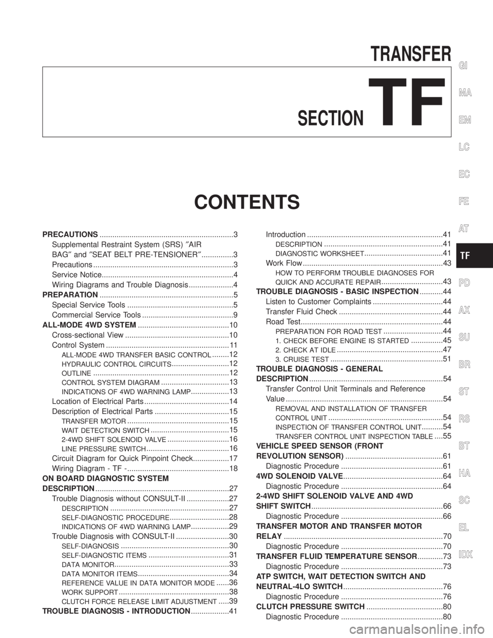
TRANSFER
SECTION
TF
CONTENTS
PRECAUTIONS...............................................................3
Supplemental Restraint System (SRS)²AIR
BAG²and²SEAT BELT PRE-TENSIONER²...............3
Precautions ..................................................................3
Service Notice..............................................................4
Wiring Diagrams and Trouble Diagnosis .....................4
PREPARATION...............................................................5
Special Service Tools ..................................................5
Commercial Service Tools ...........................................9
ALL-MODE 4WD SYSTEM...........................................10
Cross-sectional View .................................................10
Control System .......................................................... 11
ALL-MODE 4WD TRANSFER BASIC CONTROL........12
HYDRAULIC CONTROL CIRCUITS...........................12
OUTLINE................................................................12
CONTROL SYSTEM DIAGRAM................................13
INDICATIONS OF 4WD WARNING LAMP..................13
Location of Electrical Parts ........................................14
Description of Electrical Parts ...................................15
TRANSFER MOTOR................................................15
WAIT DETECTION SWITCH.....................................15
2-4WD SHIFT SOLENOID VALVE.............................16
LINE PRESSURE SWITCH.......................................16
Circuit Diagram for Quick Pinpoint Check.................17
Wiring Diagram - TF -................................................18
ON BOARD DIAGNOSTIC SYSTEM
DESCRIPTION...............................................................27
Trouble Diagnosis without CONSULT-II ....................27
DESCRIPTION........................................................27
SELF-DIAGNOSTIC PROCEDURE............................28
INDICATIONS OF 4WD WARNING LAMP..................29
Trouble Diagnosis with CONSULT-II .........................30
SELF-DIAGNOSIS...................................................30
SELF-DIAGNOSTIC ITEMS......................................31
DATA MONITOR......................................................33
DATA MONITOR ITEMS...........................................34
REFERENCE VALUE IN DATA MONITOR MODE......36
WORK SUPPORT....................................................38
CLUTCH FORCE RELEASE LIMIT ADJUSTMENT.....39
TROUBLE DIAGNOSIS - INTRODUCTION..................41Introduction ................................................................41
DESCRIPTION........................................................41
DIAGNOSTIC WORKSHEET.....................................41
Work Flow ..................................................................43
HOW TO PERFORM TROUBLE DIAGNOSES FOR
QUICK AND ACCURATE REPAIR
.............................43
TROUBLE DIAGNOSIS - BASIC INSPECTION...........44
Listen to Customer Complaints .................................44
Transfer Fluid Check .................................................44
Road Test...................................................................44
PREPARATION FOR ROAD TEST............................44
1. CHECK BEFORE ENGINE IS STARTED...............45
2. CHECK AT IDLE..................................................47
3. CRUISE TEST.....................................................51
TROUBLE DIAGNOSIS - GENERAL
DESCRIPTION...............................................................54
Transfer Control Unit Terminals and Reference
Value ..........................................................................54
REMOVAL AND INSTALLATION OF TRANSFER
CONTROL UNIT
......................................................54
INSPECTION OF TRANSFER CONTROL UNIT..........54
TRANSFER CONTROL UNIT INSPECTION TABLE....55
VEHICLE SPEED SENSOR (FRONT
REVOLUTION SENSOR)..............................................61
Diagnostic Procedure ................................................61
4WD SOLENOID VALVE...............................................64
Diagnostic Procedure ................................................64
2-4WD SHIFT SOLENOID VALVE AND 4WD
SHIFT SWITCH..............................................................66
Diagnostic Procedure ................................................66
TRANSFER MOTOR AND TRANSFER MOTOR
RELAY...........................................................................70
Diagnostic Procedure ................................................70
TRANSFER FLUID TEMPERATURE SENSOR............73
Diagnostic Procedure ................................................73
ATP SWITCH, WAIT DETECTION SWITCH AND
NEUTRAL-4LO SWITCH...............................................76
Diagnostic Procedure ................................................76
CLUTCH PRESSURE SWITCH....................................80
Diagnostic Procedure ................................................80
GI
MA
EM
LC
EC
FE
AT
PD
AX
SU
BR
ST
RS
BT
HA
SC
EL
IDX
Page 2238 of 2395
Supplemental Restraint System (SRS) ªAIR
BAGº and ªSEAT BELT PRE-TENSIONERº
NBTF0001The Supplemental Restraint System such as ªAIR BAGº and ªSEAT BELT PRE-TENSIONERº used along with
a seat belt, helps to reduce the risk or severity of injury to the driver and front passenger for certain types of
collision. The SRS system composition which is available to INFINITI QX4 is as follows:
IFor a frontal collision
The Supplemental Restraint System consists of driver air bag module (located in the center of the steer-
ing wheel), front passenger air bag module (located on the instrument panel on passenger side), seat belt
pre-tensioners, a diagnosis sensor unit, warning lamp, wiring harness and spiral cable.
IFor a side collision
The Supplemental Restraint System consists of side air bag module (located in the outer side of front seat),
satellite sensor, diagnosis sensor unit (one of components of air bags for a frontal collision), wiring harness,
warning lamp (one of components of air bags for a frontal collision).
Information necessary to service the system safely is included in theRSsection of this Service Manual.
WARNING:
ITo avoid rendering the SRS inoperative, which could increase the risk of personal injury or death
in the event of a collision which would result in air bag inflation, all maintenance must be performed
by an authorized INFINITI dealer.
IImproper maintenance, including incorrect removal and installation of the SRS, can lead to per-
sonal injury caused by unintentional activation of the system. For removal of Spiral Cable and Air
Bag Module, see the RS section.
IDo not use electrical test equipment on any circuit related to the SRS unless instructed to in this
Service Manual. Spiral cable and wiring harnesses covered with yellow insulation tape either just
before the harness connectors or for the complete harness are related to the SRS.
SEF289H
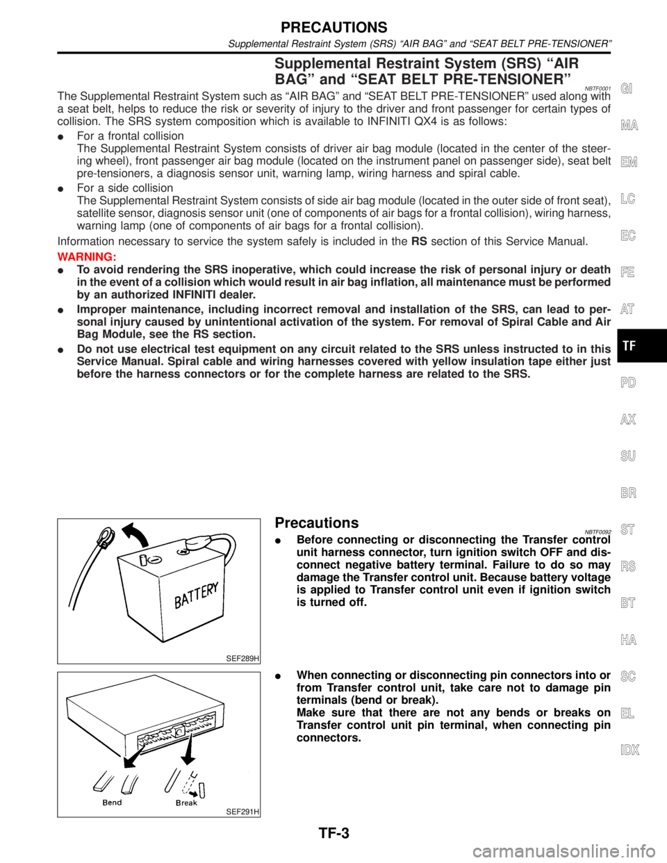
PrecautionsNBTF0092IBefore connecting or disconnecting the Transfer control
unit harness connector, turn ignition switch OFF and dis-
connect negative battery terminal. Failure to do so may
damage the Transfer control unit. Because battery voltage
is applied to Transfer control unit even if ignition switch
is turned off.
SEF291H
IWhen connecting or disconnecting pin connectors into or
from Transfer control unit, take care not to damage pin
terminals (bend or break).
Make sure that there are not any bends or breaks on
Transfer control unit pin terminal, when connecting pin
connectors.
GI
MA
EM
LC
EC
FE
AT
PD
AX
SU
BR
ST
RS
BT
HA
SC
EL
IDX
PRECAUTIONS
Supplemental Restraint System (SRS) ªAIR BAGº and ªSEAT BELT PRE-TENSIONERº
TF-3
Page 2240 of 2395
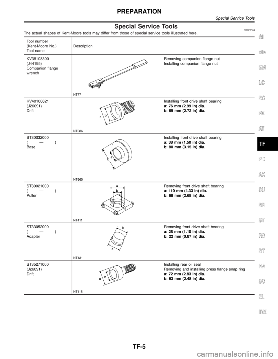
Special Service ToolsNBTF0004The actual shapes of Kent-Moore tools may differ from those of special service tools illustrated here.
Tool number
(Kent-Moore No.)
Tool nameDescription
KV38108300
(J44195)
Companion flange
wrench
NT771
Removing companion flange nut
Installing companion flange nut
KV40100621
(J26091)
Drift
NT086
Installing front drive shaft bearing
a: 76 mm (2.99 in) dia.
b: 69 mm (2.72 in) dia.
ST30032000
(Ð)
Base
NT660
Installing front drive shaft bearing
a: 38 mm (1.50 in) dia.
b: 80 mm (3.15 in) dia.
ST30021000
(Ð)
Puller
NT411
Removing front drive shaft bearing
a: 110 mm (4.33 in) dia.
b: 68 mm (2.68 in) dia.
ST33052000
(Ð)
Adapter
NT431
Removing front drive shaft bearing
a: 28 mm (1.10 in) dia.
b: 22 mm (0.87 in) dia.
ST35271000
(J26091)
Drift
NT115
Installing rear oil seal
Removing and installing press flange snap ring
a: 72 mm (2.83 in) dia.
b: 63 mm (2.48 in) dia.
GI
MA
EM
LC
EC
FE
AT
PD
AX
SU
BR
ST
RS
BT
HA
SC
EL
IDX
PREPARATION
Special Service Tools
TF-5
Page 2242 of 2395
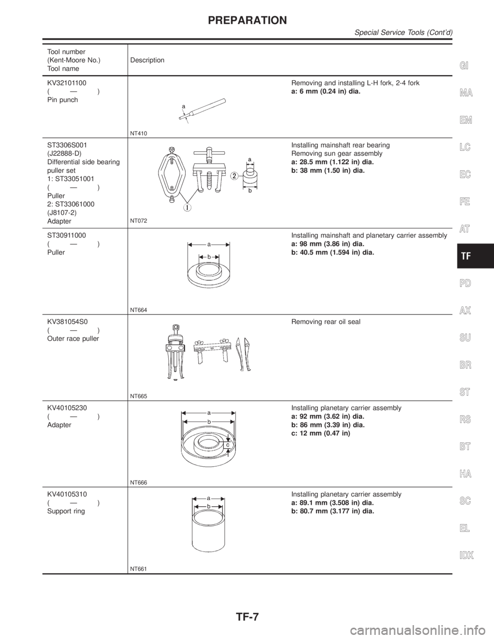
Tool number
(Kent-Moore No.)
Tool nameDescription
KV32101100
(Ð)
Pin punch
NT410
Removing and installing L-H fork, 2-4 fork
a: 6 mm (0.24 in) dia.
ST3306S001
(J22888-D)
Differential side bearing
puller set
1: ST33051001
(Ð)
Puller
2: ST33061000
(J8107-2)
Adapter
NT072
Installing mainshaft rear bearing
Removing sun gear assembly
a: 28.5 mm (1.122 in) dia.
b: 38 mm (1.50 in) dia.
ST30911000
(Ð)
Puller
NT664
Installing mainshaft and planetary carrier assembly
a: 98 mm (3.86 in) dia.
b: 40.5 mm (1.594 in) dia.
KV381054S0
(Ð)
Outer race puller
NT665
Removing rear oil seal
KV40105230
(Ð)
Adapter
NT666
Installing planetary carrier assembly
a: 92 mm (3.62 in) dia.
b: 86 mm (3.39 in) dia.
c: 12 mm (0.47 in)
KV40105310
(Ð)
Support ring
NT661
Installing planetary carrier assembly
a: 89.1 mm (3.508 in) dia.
b: 80.7 mm (3.177 in) dia.
GI
MA
EM
LC
EC
FE
AT
PD
AX
SU
BR
ST
RS
BT
HA
SC
EL
IDX
PREPARATION
Special Service Tools (Cont'd)
TF-7