Page 2196 of 2395
RemovalNBST0021
SST846C
1. Power steering gear assembly
2. Steering column lower joint3. Transfer gear assembly 4. Steering column upper joint
SST609C
1. Set wheels in the straight-ahead position.
2. Straight-forward position is indicated by a protrusion on the
power steering gear rear cover cap and matching mark on the
rear housing.
SST610C
3. Remove steering column upper and lower joint from transfer
gear.
4. Remove transfer gear assembly.
GI
MA
EM
LC
EC
FE
AT
TF
PD
AX
SU
BR
RS
BT
HA
SC
EL
IDX
STEERING TRANSFER GEAR
Removal
ST-15
Page 2198 of 2395
ComponentsNBST0026
SST618CB
1. Rear cover cap
2. Rear housing assembly
3. Pinion seal ring
4. Pinion assembly
5. O-ring
6. Shim
7. Pinion oil seal
8. Lock nut
9. Adjusting screw
10. Spring11. Retainer
12. Gear housing assembly
13. Rack oil seal
14. Rack assembly
15. Rack seal ring
16. O-ring
17. O-ring
18. Rack bushing
19. Rack oil seal
20. Snap ring21. End cover assembly
22. Boot clamp
23. Dust boot
24. Boot clamp
25. Lock plate
26. Tie-rod inner socket
27. Tie-rod
28. Tie-rod outer socket
29. Cotter pin
30. Cylinder tube
GI
MA
EM
LC
EC
FE
AT
TF
PD
AX
SU
BR
RS
BT
HA
SC
EL
IDX
POWER STEERING GEAR AND LINKAGE
Components
ST-17
Page 2200 of 2395

in high-pressure connector. Take care to install the proper
O-ring.
SST616C
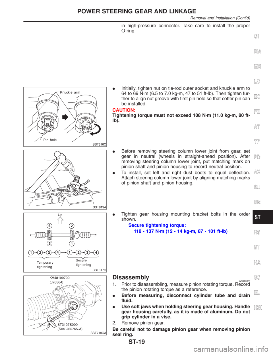
IInitially, tighten nut on tie-rod outer socket and knuckle arm to
64 to 69 N´m (6.5 to 7.0 kg-m, 47 to 51 ft-lb). Then tighten fur-
ther to align nut groove with first pin hole so that cotter pin can
be installed.
CAUTION:
Tightening torque must not exceed 108 N´m (11.0 kg-m, 80 ft-
lb).
SST819A
IBefore removing steering column lower joint from gear, set
gear in neutral (wheels in straight-ahead position). After
removing steering column lower joint, put matching mark on
pinion shaft and pinion housing to record neutral position.
ITo install, set left and right dust boots to equal deflection.
Attach steering column lower joint by aligning matching marks
of pinion shaft and pinion housing.
SST617C
ITighten gear housing mounting bracket bolts in the order
shown.
Secure tightening torque:
118 - 137 N´m (12 - 14 kg-m, 87 - 101 ft-lb)
SST718CA
DisassemblyNBST00281. Prior to disassembling, measure pinion rotating torque. Record
the pinion rotating torque as a reference.
IBefore measuring, disconnect cylinder tube and drain
fluid.
IUse soft jaws when holding steering gear housing. Handle
gear housing carefully, as it is made of aluminum. Do not
grip cylinder in a vise.
2. Remove pinion gear.
Be careful not to damage pinion gear when removing pinion
seal ring.
GI
MA
EM
LC
EC
FE
AT
TF
PD
AX
SU
BR
RS
BT
HA
SC
EL
IDX
POWER STEERING GEAR AND LINKAGE
Removal and Installation (Cont'd)
ST-19
Page 2202 of 2395

SST468C
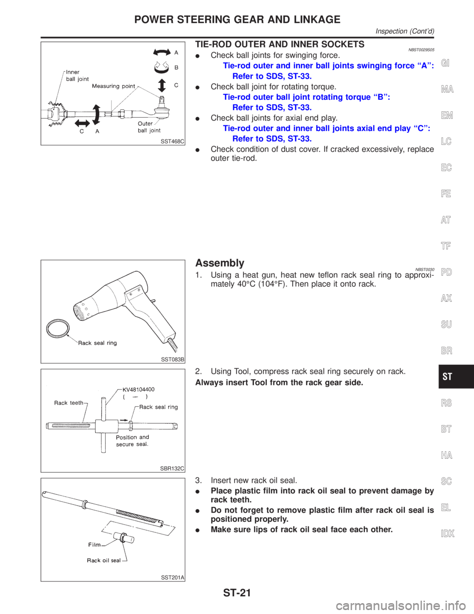
TIE-ROD OUTER AND INNER SOCKETSNBST0029S05ICheck ball joints for swinging force.
Tie-rod outer and inner ball joints swinging force ªAº:
Refer to SDS, ST-33.
ICheck ball joint for rotating torque.
Tie-rod outer ball joint rotating torque ªBº:
Refer to SDS, ST-33.
ICheck ball joints for axial end play.
Tie-rod outer and inner ball joints axial end play ªCº:
Refer to SDS, ST-33.
ICheck condition of dust cover. If cracked excessively, replace
outer tie-rod.
SST083B
AssemblyNBST00301. Using a heat gun, heat new teflon rack seal ring to approxi-
mately 40ÉC (104ÉF). Then place it onto rack.
SBR132C
2. Using Tool, compress rack seal ring securely on rack.
Always insert Tool from the rack gear side.
SST201A
3. Insert new rack oil seal.
IPlace plastic film into rack oil seal to prevent damage by
rack teeth.
IDo not forget to remove plastic film after rack oil seal is
positioned properly.
IMake sure lips of rack oil seal face each other.
GI
MA
EM
LC
EC
FE
AT
TF
PD
AX
SU
BR
RS
BT
HA
SC
EL
IDX
POWER STEERING GEAR AND LINKAGE
Inspection (Cont'd)
ST-21
Page 2204 of 2395
SST074B
9. Install pinion bearing adjusting shim(s).
IWhenever pinion assembly, gear housing and rear housing are
disassembled, replace shim(s) with new ones. Always use the
same number of shim(s) when replacing.
SST085B
10. Install new pinion seal ring (made of Teflon) on pinion gear
assembly.
IUsing a heat gun, heat pinion seal ring to approximately 40ÉC
(104ÉF) before installing it onto pinion gear assembly.
IMake sure pinion seal ring is properly settled in valve groove.
SST075B
11. Apply a coat of multi-purpose grease to needle bearing roller
and oil seal lip.
SST552
12. Install pinion assembly to rear housing.
Be careful not to damage pinion oil seal.
SST133C
13. Apply a coat of multi-purpose grease to new rear oil seal lip
before installing rear housing.
GI
MA
EM
LC
EC
FE
AT
TF
PD
AX
SU
BR
RS
BT
HA
SC
EL
IDX
POWER STEERING GEAR AND LINKAGE
Assembly (Cont'd)
ST-23
Page 2206 of 2395

SST718CA
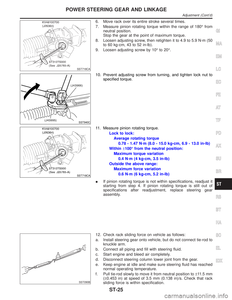
6. Move rack over its entire stroke several times.
7. Measure pinion rotating torque within the range of 180É from
neutral position.
Stop the gear at the point of maximum torque.
8. Loosen adjusting screw, then retighten it to 4.9 to 5.9 N´m (50
to 60 kg-cm, 43 to 52 in-lb).
9. Loosen adjusting screw by 10É to 20É.
SST940C
10. Prevent adjusting screw from turning, and tighten lock nut to
specified torque.
SST718CA
11. Measure pinion rotating torque.
Lock to lock:
Average rotating torque
0.78 - 1.47 N´m (8.0 - 15.0 kg-cm, 6.9 - 13.0 in-lb)
Within±100É from the neutral position:
Maximum torque variation
0.4 N´m (4 kg-cm, 3.5 in-lb)
Outside the above range:
Maximum force variation
0.6 N´m (6 kg-cm, 5.2 in-lb)
IIf pinion rotating torque is not within specifications, readjust it
starting from step 4. If pinion rotating torque is still out of
specifications after readjustment, replace steering gear
assembly.
SST090B
12. Check rack sliding force on vehicle as follows:
a. Install steering gear onto vehicle, but do not connect tie-rod to
knuckle arm.
b. Connect all piping and fill with steering fluid.
c. Start engine and bleed air completely.
d. Disconnect steering column lower joint from the gear.
e. Keep engine at idle and make sure steering fluid has reached
normal operating temperature.
f. Pull tie-rod slowly to move it from neutral position to±11.5 mm
(±0.453 in) at speed of 3.5 mm (0.138 in)/s. Check that rack
sliding force is within specification.
GI
MA
EM
LC
EC
FE
AT
TF
PD
AX
SU
BR
RS
BT
HA
SC
EL
IDX
POWER STEERING GEAR AND LINKAGE
Adjustment (Cont'd)
ST-25
Page 2208 of 2395
ComponentsNBST0032
SST924C
1. Pulley
2. Front bracket
3. Oil seal
4. Suction pipe
5. O-ring
6. Casing
7. Flow control valve spring
8. Flow control A valve9. Dowel pin
10. Flow control B valve assembly
11. Side plate (Front)
12. Cam ring
13. Rotor
14. Vane
15. Snap ring16. Side plate (Rear)
17. Side plate inner seal
18. Side plate outer seal
19. O-ring
20. Rear cover
21. Power steering pump bracket
22. Copper washer
SST925C
Pre-disassembly InspectionNBST0033Disassemble the power steering oil pump only if the following items
are found.
IOil leak from any point shown in the figure.
IDeformed or damaged pulley.
IPoor performance.
GI
MA
EM
LC
EC
FE
AT
TF
PD
AX
SU
BR
RS
BT
HA
SC
EL
IDX
POWER STEERING OIL PUMP
Components
ST-27
Page 2210 of 2395

InspectionNBST0035IIf pulley is cracked or deformed, replace it.
IIf an oil leak is found around pulley shaft oil seal, replace the
seal.
ICheck the casing and the inside of the rear body for damage.
If damages are found in the rear body, replace the entire rear
body. If the casing is damaged, replace the entire power steer-
ing pump as an assembly.
ICheck the cam ring for damage. If damage is found, replace
the cam ring, rotor and vane as a set.
ICheck the side plates (front and rear) for damage. If damage
is found, replace the side plates as a set (front and rear).
SST934C
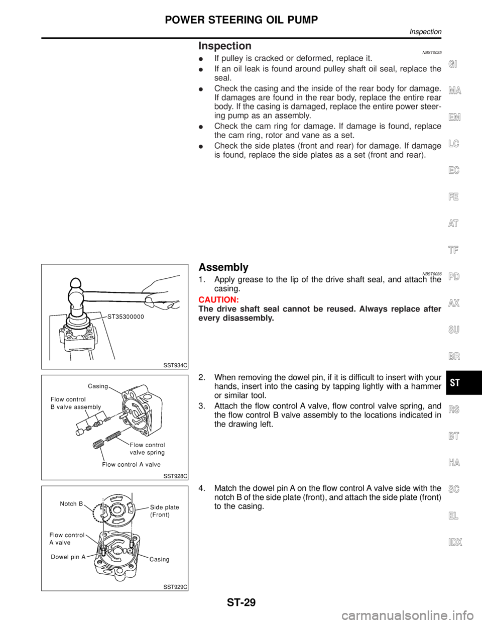
AssemblyNBST00361. Apply grease to the lip of the drive shaft seal, and attach the
casing.
CAUTION:
The drive shaft seal cannot be reused. Always replace after
every disassembly.
SST928C
2. When removing the dowel pin, if it is difficult to insert with your
hands, insert into the casing by tapping lightly with a hammer
or similar tool.
3. Attach the flow control A valve, flow control valve spring, and
the flow control B valve assembly to the locations indicated in
the drawing left.
SST929C
4. Match the dowel pin A on the flow control A valve side with the
notch B of the side plate (front), and attach the side plate (front)
to the casing.
GI
MA
EM
LC
EC
FE
AT
TF
PD
AX
SU
BR
RS
BT
HA
SC
EL
IDX
POWER STEERING OIL PUMP
Inspection
ST-29