2001 INFINITI QX4 display
[x] Cancel search: displayPage 1097 of 2395
IEVAP canister vent control valve
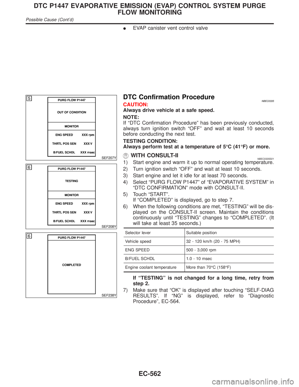
SEF207Y
SEF208Y
SEF238Y
DTC Confirmation ProcedureNBEC0335CAUTION:
Always drive vehicle at a safe speed.
NOTE:
If ªDTC Confirmation Procedureº has been previously conducted,
always turn ignition switch ªOFFº and wait at least 10 seconds
before conducting the next test.
TESTING CONDITION:
Always perform test at a temperature of 5ÉC (41ÉF) or more.
WITH CONSULT-IINBEC0335S011) Start engine and warm it up to normal operating temperature.
2) Turn ignition switch ªOFFº and wait at least 10 seconds.
3) Start engine and let it idle for at least 70 seconds.
4) Select ªPURG FLOW P1447º of ªEVAPORATIVE SYSTEMº in
ªDTC CONFIRMATIONº mode with CONSULT-II.
5) Touch ªSTARTº.
If ªCOMPLETEDº is displayed, go to step 7.
6) When the following conditions are met, ªTESTINGº will be dis-
played on the CONSULT-II screen. Maintain the conditions
continuously until ªTESTINGº changes to ªCOMPLETEDº. (It
will take at least 35 seconds.)
Selector lever Suitable position
Vehicle speed 32 - 120 km/h (20 - 75 MPH)
ENG SPEED 500 - 3,000 rpm
B/FUEL SCHDL 1.0 - 10 msec
Engine coolant temperature More than 70ÉC (158ÉF)
If ªTESTINGº is not changed for a long time, retry from
step 2.
7) Make sure that ªOKº is displayed after touching ªSELF-DIAG
RESULTSº. If ªNGº is displayed, refer to ªDiagnostic
Procedureº, EC-564.
DTC P1447 EVAPORATIVE EMISSION (EVAP) CONTROL SYSTEM PURGE
FLOW MONITORING
Possible Cause (Cont'd)
EC-562
Page 1108 of 2395
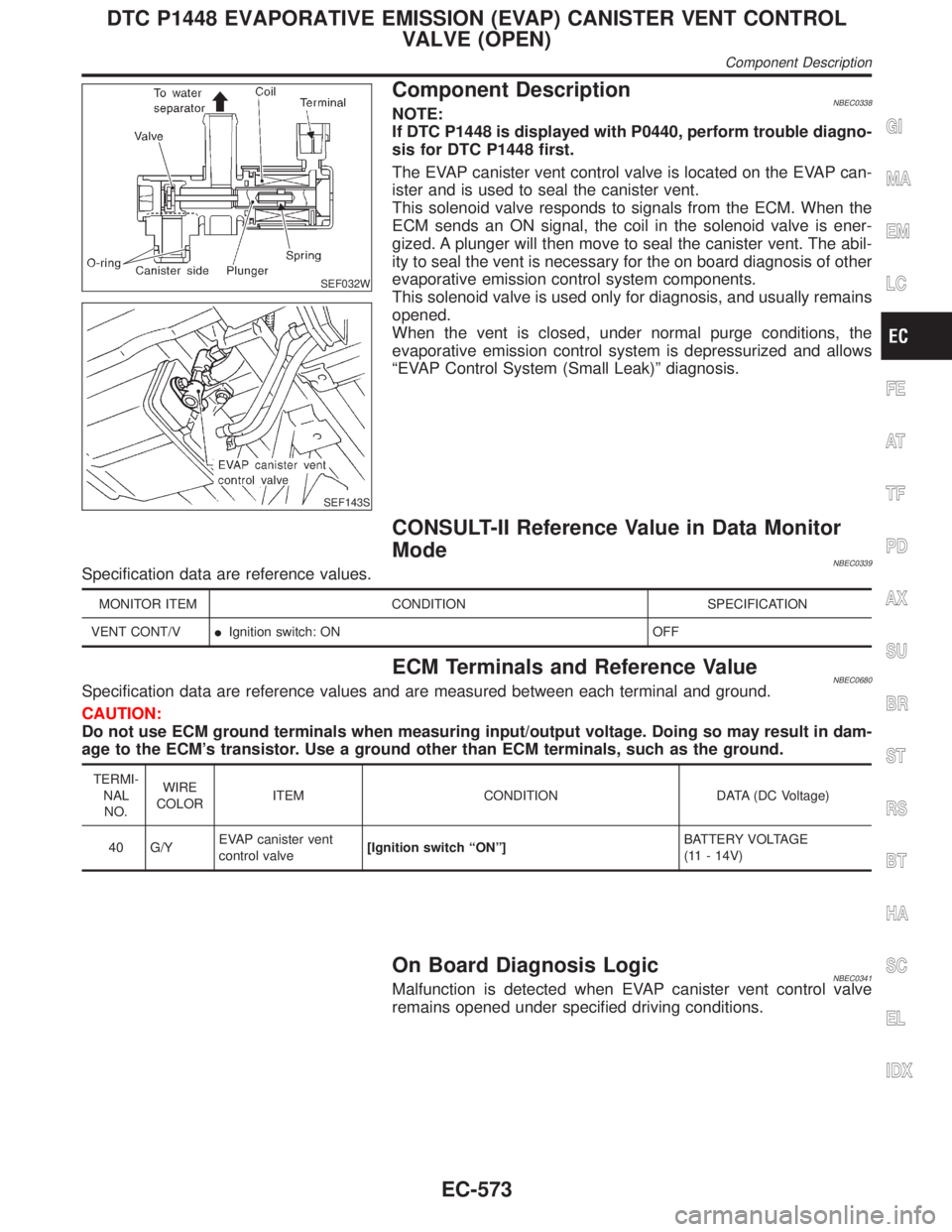
SEF032W
SEF143S
Component DescriptionNBEC0338NOTE:
If DTC P1448 is displayed with P0440, perform trouble diagno-
sis for DTC P1448 first.
The EVAP canister vent control valve is located on the EVAP can-
ister and is used to seal the canister vent.
This solenoid valve responds to signals from the ECM. When the
ECM sends an ON signal, the coil in the solenoid valve is ener-
gized. A plunger will then move to seal the canister vent. The abil-
ity to seal the vent is necessary for the on board diagnosis of other
evaporative emission control system components.
This solenoid valve is used only for diagnosis, and usually remains
opened.
When the vent is closed, under normal purge conditions, the
evaporative emission control system is depressurized and allows
ªEVAP Control System (Small Leak)º diagnosis.
CONSULT-II Reference Value in Data Monitor
Mode
NBEC0339Specification data are reference values.
MONITOR ITEM CONDITION SPECIFICATION
VENT CONT/VIIgnition switch: ON OFF
ECM Terminals and Reference ValueNBEC0680Specification data are reference values and are measured between each terminal and ground.
CAUTION:
Do not use ECM ground terminals when measuring input/output voltage. Doing so may result in dam-
age to the ECM's transistor. Use a ground other than ECM terminals, such as the ground.
TERMI-
NAL
NO.WIRE
COLORITEM CONDITION DATA (DC Voltage)
40 G/YEVAP canister vent
control valve[Ignition switch ªONº]BATTERY VOLTAGE
(11 - 14V)
On Board Diagnosis LogicNBEC0341Malfunction is detected when EVAP canister vent control valve
remains opened under specified driving conditions.
GI
MA
EM
LC
FE
AT
TF
PD
AX
SU
BR
ST
RS
BT
HA
SC
EL
IDX
DTC P1448 EVAPORATIVE EMISSION (EVAP) CANISTER VENT CONTROL
VALVE (OPEN)
Component Description
EC-573
Page 1109 of 2395
Possible CauseNBEC0591IEVAP canister vent control valve
IEVAP control system pressure sensor and circuit
IBlocked rubber tube to EVAP canister vent control valve
IWater separator
IEVAP canister is saturated with water.
IVacuum cut valve
DTC Confirmation ProcedureNBEC0342NOTE:
IIf DTC P1448 is displayed with P0440 or P1440, perform
trouble diagnosis for DTC P1448 first.
IIf ªDTC Confirmation Procedureº has been previously
conducted, always turn ignition switch ªOFFº and wait at least
10 seconds before conducting the next test.
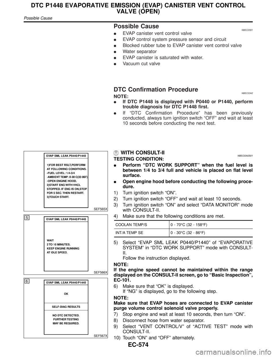
SEF565X
SEF566X
SEF567X
WITH CONSULT-IINBEC0342S01TESTING CONDITION:
IPerform ªDTC WORK SUPPORTº when the fuel level is
between 1/4 to 3/4 full and vehicle is placed on flat level
surface.
IOpen engine hood before conducting the following proce-
dure.
1) Turn ignition switch ªONº.
2) Turn ignition switch ªOFFº and wait at least 10 seconds.
3) Turn ignition switch ªONº and select ªDATA MONITORº mode
with CONSULT-II.
4) Make sure that the following conditions are met.
COOLAN TEMP/S 0 - 70ÉC (32 - 158ÉF)
INT/A TEMP SE 0 - 30ÉC (32 - 86ÉF)
5) Select ªEVAP SML LEAK P0440/P1440º of ªEVAPORATIVE
SYSTEMº in ªDTC WORK SUPPORTº mode with CONSULT-
II.
Follow the instruction displayed.
NOTE:
If the engine speed cannot be maintained within the range
displayed on the CONSULT-II screen, go to ªBasic Inspectionº,
EC-101.
6) Make sure that ªOKº is displayed.
If ªNGº is displayed, go to the following step.
NOTE:
Make sure that EVAP hoses are connected to EVAP canister
purge volume control solenoid valve properly.
7) Stop engine and wait at least 10 seconds, then turn ªONº.
8) Disconnect hose from water separator.
9) Select ªVENT CONTROL/Vº of ªACTIVE TESTº mode with
CONSULT-II.
10) Touch ªONº and ªOFFº alternately.
DTC P1448 EVAPORATIVE EMISSION (EVAP) CANISTER VENT CONTROL
VALVE (OPEN)
Possible Cause
EC-574
Page 1127 of 2395
On Board Diagnosis LogicNBEC0356Malfunction is detected when vacuum cut valve bypass valve does
not operate properly.
Possible CauseNBEC0593IVacuum cut valve bypass valve
IVacuum cut valve
IBypass hoses for clogging
IEVAP control system pressure sensor and circuit
IEVAP canister vent control valve
IHose between fuel tank and vacuum cut valve clogged
IHose between vacuum cut valve and EVAP canister clogged
IEVAP canister
IEVAP purge port of fuel tank for clogging
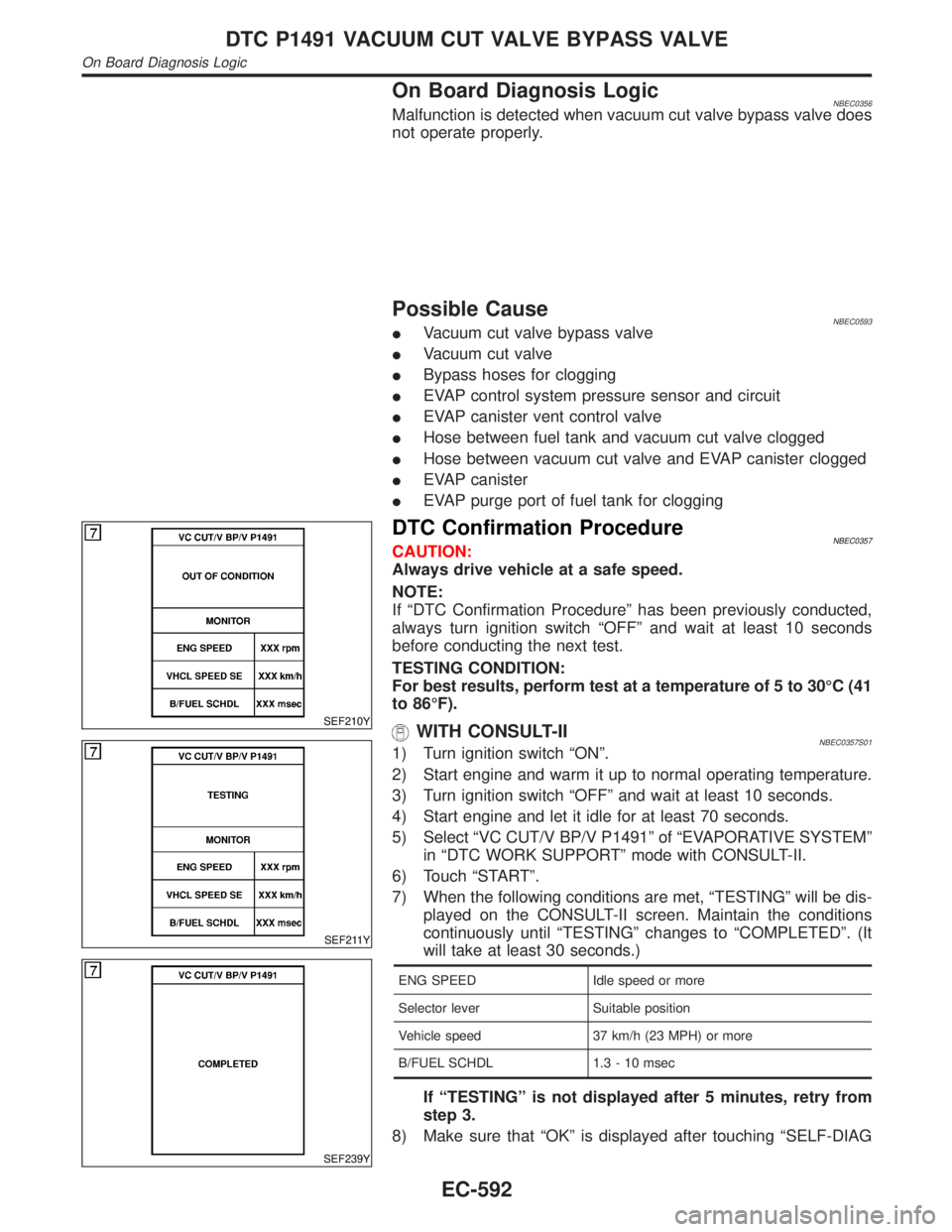
SEF210Y
SEF211Y
SEF239Y
DTC Confirmation ProcedureNBEC0357CAUTION:
Always drive vehicle at a safe speed.
NOTE:
If ªDTC Confirmation Procedureº has been previously conducted,
always turn ignition switch ªOFFº and wait at least 10 seconds
before conducting the next test.
TESTING CONDITION:
For best results, perform test at a temperature of 5 to 30ÉC (41
to 86ÉF).
WITH CONSULT-IINBEC0357S011) Turn ignition switch ªONº.
2) Start engine and warm it up to normal operating temperature.
3) Turn ignition switch ªOFFº and wait at least 10 seconds.
4) Start engine and let it idle for at least 70 seconds.
5) Select ªVC CUT/V BP/V P1491º of ªEVAPORATIVE SYSTEMº
in ªDTC WORK SUPPORTº mode with CONSULT-II.
6) Touch ªSTARTº.
7) When the following conditions are met, ªTESTINGº will be dis-
played on the CONSULT-II screen. Maintain the conditions
continuously until ªTESTINGº changes to ªCOMPLETEDº. (It
will take at least 30 seconds.)
ENG SPEED Idle speed or more
Selector lever Suitable position
Vehicle speed 37 km/h (23 MPH) or more
B/FUEL SCHDL 1.3 - 10 msec
If ªTESTINGº is not displayed after 5 minutes, retry from
step 3.
8) Make sure that ªOKº is displayed after touching ªSELF-DIAG
DTC P1491 VACUUM CUT VALVE BYPASS VALVE
On Board Diagnosis Logic
EC-592
Page 1128 of 2395
RESULTSº. If ªNGº is displayed, refer to ªDiagnostic
Procedureº, EC-595.
SEF530Q
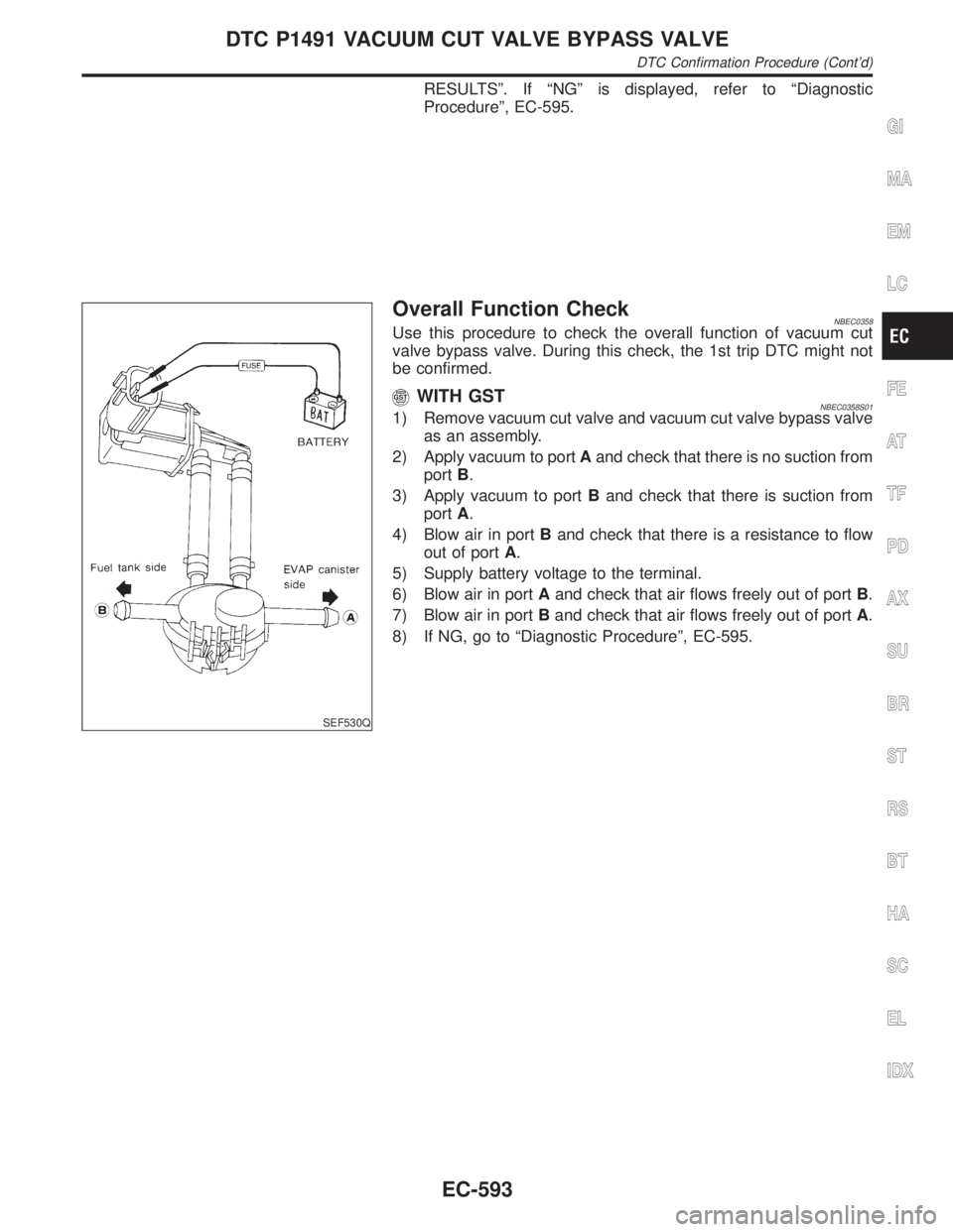
Overall Function CheckNBEC0358Use this procedure to check the overall function of vacuum cut
valve bypass valve. During this check, the 1st trip DTC might not
be confirmed.
WITH GSTNBEC0358S011) Remove vacuum cut valve and vacuum cut valve bypass valve
as an assembly.
2) Apply vacuum to portAand check that there is no suction from
portB.
3) Apply vacuum to portBand check that there is suction from
portA.
4) Blow air in portBand check that there is a resistance to flow
out of portA.
5) Supply battery voltage to the terminal.
6) Blow air in portAand check that air flows freely out of portB.
7) Blow air in portBand check that air flows freely out of portA.
8) If NG, go to ªDiagnostic Procedureº, EC-595.
GI
MA
EM
LC
FE
AT
TF
PD
AX
SU
BR
ST
RS
BT
HA
SC
EL
IDX
DTC P1491 VACUUM CUT VALVE BYPASS VALVE
DTC Confirmation Procedure (Cont'd)
EC-593
Page 1266 of 2395
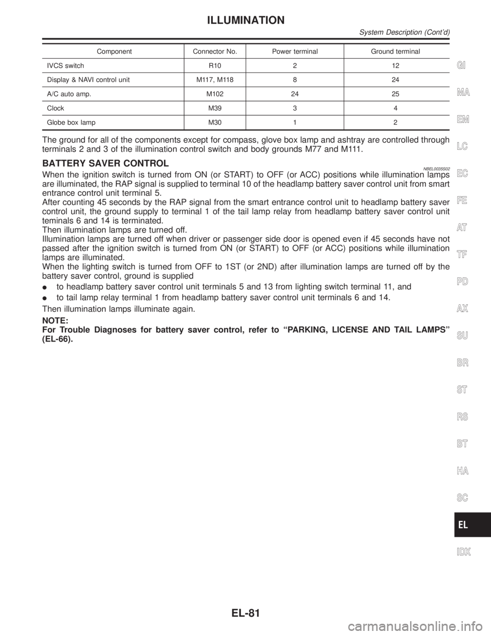
Component Connector No. Power terminal Ground terminal
IVCS switch R10 2 12
Display & NAVI control unit M117, M118 8 24
A/C auto amp. M102 24 25
Clock M39 3 4
Globe box lamp M30 1 2
The ground for all of the components except for compass, glove box lamp and ashtray are controlled through
terminals 2 and 3 of the illumination control switch and body grounds M77 and M111.
BATTERY SAVER CONTROLNBEL0035S02When the ignition switch is turned from ON (or START) to OFF (or ACC) positions while illumination lamps
are illuminated, the RAP signal is supplied to terminal 10 of the headlamp battery saver control unit from smart
entrance control unit terminal 5.
After counting 45 seconds by the RAP signal from the smart entrance control unit to headlamp battery saver
control unit, the ground supply to terminal 1 of the tail lamp relay from headlamp battery saver control unit
teminals 6 and 14 is terminated.
Then illumination lamps are turned off.
Illumination lamps are turned off when driver or passenger side door is opened even if 45 seconds have not
passed after the ignition switch is turned from ON (or START) to OFF (or ACC) positions while illumination
lamps are illuminated.
When the lighting switch is turned from OFF to 1ST (or 2ND) after illumination lamps are turned off by the
battery saver control, ground is supplied
Ito headlamp battery saver control unit terminals 5 and 13 from lighting switch terminal 11, and
Ito tail lamp relay terminal 1 from headlamp battery saver control unit terminals 6 and 14.
Then illumination lamps illuminate again.
NOTE:
For Trouble Diagnoses for battery saver control, refer to ªPARKING, LICENSE AND TAIL LAMPSº
(EL-66).
GI
MA
EM
LC
EC
FE
AT
TF
PD
AX
SU
BR
ST
RS
BT
HA
SC
IDX
ILLUMINATION
System Description (Cont'd)
EL-81
Page 1279 of 2395

Component Parts and Harness Connector
Location
NBEL0041
SEL351X
System DescriptionNBEL0042UNIFIED CONTROL METERNBEL0042S06ISpeedometer, odo/trip meter, tachometer, fuel gauge and water temperature gauge are controlled totally
by control unit.
IDigital meter is adopted for odo/trip meter.*
*The record of the odo meter is kept even if the battery cable is disconnected. The record of the trip meter
is erased when the battery cable is disconnected.
IOdo/trip meter is indicated for about 30 seconds after ignition switch has been turned OFF.
IOdo/trip meter segment can be checked in diagnosis mode.
IMeter/gauge can be checked in diagnosis mode.
HOW TO CHANGE THE DISPLAY FOR ODO/TRIP METERNBEL0042S07
SEL175W
NOTE:
Turn ignition switch to the ªONº position to operate odo/trip meter.
METERS AND GAUGES
Component Parts and Harness Connector Location
EL-94
Page 1280 of 2395
![INFINITI QX4 2001 Factory Service Manual POWER SUPPLY AND GROUND CIRCUITNBEL0042S08Power is supplied at all times
Ithrough 7.5A fuse [No. 24, located in the fuse block (J/B)]
Ito combination meter terminal 62.
With the ignition switch in the INFINITI QX4 2001 Factory Service Manual POWER SUPPLY AND GROUND CIRCUITNBEL0042S08Power is supplied at all times
Ithrough 7.5A fuse [No. 24, located in the fuse block (J/B)]
Ito combination meter terminal 62.
With the ignition switch in the](/manual-img/42/57027/w960_57027-1279.png)
POWER SUPPLY AND GROUND CIRCUITNBEL0042S08Power is supplied at all times
Ithrough 7.5A fuse [No. 24, located in the fuse block (J/B)]
Ito combination meter terminal 62.
With the ignition switch in the ON or START position, power is supplied
Ithrough 10A fuse [No. 8, located in the fuse block (J/B)]
Ito combination meter terminal 66.
Ground is supplied
Ito combination meter terminal 59
Ithrough body grounds M4, M66 and M147.
WATER TEMPERATURE GAUGENBEL0042S01The water temperature gauge indicates the engine coolant temperature. The reading on the gauge is based
on the resistance of the thermal transmitter.
As the temperature of the coolant increases, the resistance of the thermal transmitter decreases. A variable
ground is supplied to terminal 18 of the combination meter for the water temperature gauge. The needle on
the gauge moves from ªCº to ªHº.
TACHOMETERNBEL0042S02The tachometer indicates engine speed in revolutions per minute (rpm).
The tachometer is regulated by a signal
Ifrom terminal 25 of the ECM
Ito combination meter terminal 16 for the tachometer.
FUEL GAUGENBEL0042S03The fuel gauge indicates the approximate fuel level in the fuel tank.
The fuel gauge is regulated by a variable ground signal supplied
Ito combination meter terminal 17 for the fuel gauge
Ifrom terminal 3 of the fuel level sensor unit
Ithrough terminal 2 of the fuel level sensor unit and
Ithrough body grounds B11, B22 and D210.
SPEEDOMETERNBEL0042S04The vehicle speed sensor provides a voltage signal to the combination meter for the speedometer.
The voltage is supplied
Ifrom combination meter terminal 15 for the speedometer
Ito terminal 2 of the vehicle speed sensor.
The speedometer converts the voltage into the vehicle speed displayed.
GI
MA
EM
LC
EC
FE
AT
TF
PD
AX
SU
BR
ST
RS
BT
HA
SC
IDX
METERS AND GAUGES
System Description (Cont'd)
EL-95