Page 2275 of 2395
SMT968D
1. Current CLUTCH FORCE RELEASE LIMIT value ª0.3 kg-mº
appears under ªCONDITION SETTINGº on CONSULT-II dis-
play.
2. Touch ª1.2º on the display.
SMT969D
3. Display changes to ªNOW ADJUSTINGº in a short time.
SMT970D
4. When clutch force release limit value is set to ª1.2 kg-mº, cur-
rent value ª0.3 kg-mº shown on display will be replaced by ª1.2
kg-mº and ªADJUSTING COMPLETEº will appear at the same
time. Clutch force release limit value setting is now complete.
ON BOARD DIAGNOSTIC SYSTEM DESCRIPTION
Trouble Diagnosis with CONSULT-II (Cont'd)
TF-40
Page 2290 of 2395

SMT772D
TRANSFER CONTROL UNIT INSPECTION TABLENBTF0018S02(Data are reference values.)
Terminal
No.Item Condition Judgement standard
12-4WD shift solenoid
valve
&
4WD shift switch is set to ª2WDº
position.Less than 1V
4WD shift switch is set to any posi-
tion other than ª2WDº.Battery voltage
24WD shift indicator lamp
(2WD)
Lamp lights while system is operating
properly.Less than 1V
&
2WD indicator lamp does not come
on.Battery voltage
3 Ground Ð Ð
4Transfer shift relay
(High)While actuator is operating
(4H,4LO)Battery voltage
Actuator does not operate. Less than 1V
5 4WD warning lampLamp comes ON. (when engine is
stopped.)
(Fail-safe condition appears on
display, engine is stopped, actuator
position detection switch is
inoperative, oil temperature is too
high and/or tires of different size are
installed.)Less than 1V
Except above Battery voltage
6 Ground Ð Ð Ð
7 PNP switch (R position)
&
A/T selector lever is set to ªreverseº
position.Battery voltage
A/T selector lever is set to any posi-
tion other than ªreverseº.Less than 1V
8ÐÐÐÐ
GI
MA
EM
LC
EC
FE
AT
PD
AX
SU
BR
ST
RS
BT
HA
SC
EL
IDX
TROUBLE DIAGNOSIS Ð GENERAL DESCRIPTION
Transfer Control Unit Terminals and Reference Value (Cont'd)
TF-55
Page 2315 of 2395
Diagnostic ProcedureNBTF0025
1 CHECK MALFUNCTION
Is this malfunction detected only while driving in reverse?
YesorNo
Ye s©CHECK A/T PNP SWITCH ªRº POSITION.
Refer to AT-99, ªDTC P0705 Park/Neutral Position Switchº.
No©GO TO 2.
2 CHECK OTHER MALFUNCTION
Are other malfunctions also detected by self-diagnosis and CONSULT-II?
Refer to ªTrouble Diagnosis without CONSULT-IIº, TF-27 and ªTrouble Diagnosis with CONSULT-IIº, TF-30.
YesorNo
Ye s©CHECK FOR OTHER MALFUNCTIONS.
(When other malfunctions are eliminated, clutch pressure switch malfunction display may
disappear.)
No©GO TO 3.
3 CHECK 2-4WD SHIFT SOLENOID VALVE AND 4WD SHIFT SWITCH CIRCUITS
Check 2-4WD shift solenoid valve and 4WD shift switch circuits.
OK or NG
OK©GO TO 4.
NG©Check, repair or replace faulty parts.
4 CHECK INPUT SIGNAL
WITH CONSULT-II©GO TO 5.
WITHOUT CONSULT-II©GO TO 6.
CLUTCH PRESSURE SWITCH
Diagnostic Procedure
TF-80
Page 2318 of 2395
Diagnostic ProcedureNBTF0026
1 CHECK MALFUNCTION
Is this malfunction detected only while driving in reverse?
YesorNo
Ye s©CHECK A/T PNP SWITCH ªRº POSITION.
Refer to AT-99, ªDTC P0705 Park/Neutral Position Switchº.
No©GO TO 2.
2 CHECK OTHER MALFUNCTIONS
Are other malfunctions also detected by self-diagnosis and CONSULT-II?
Refer to ªTrouble Diagnosis without CONSULT-IIº, TF-27 and ªTrouble Diagnosis with CONSULT-IIº, TF-30.
YesorNo
Ye s©CHECK FOR OTHER MALFUNCTIONS.
(When other malfunctions are eliminated, line pressure switch malfunction display may
disappear.)
No©GO TO 3.
3 CHECK INPUT SIGNAL
WITH CONSULT-II©GO TO 4.
WITHOUT CONSULT-II©GO TO 5.
GI
MA
EM
LC
EC
FE
AT
PD
AX
SU
BR
ST
RS
BT
HA
SC
EL
IDX
LINE PRESSURE SWITCH
Diagnostic Procedure
TF-83
Page 2323 of 2395

Diagnostic ProcedureNBTF0028
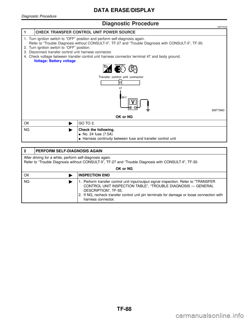
1 CHECK TRANSFER CONTROL UNIT POWER SOURCE
1. Turn ignition switch to ªOFFº position and perform self-diagnosis again.
Refer to ªTrouble Diagnosis without CONSULT-IIº, TF-27 and ªTrouble Diagnosis with CONSULT-IIº, TF-30.
2. Turn ignition switch to ªOFFº position.
3. Disconnect transfer control unit harness connector.
4. Check voltage between transfer control unit harness connector terminal 47 and body ground.
Voltage: Battery voltage
SMT794D
OK or NG
OK©GO TO 2.
NG©Check the following.
INo. 24 fuse (7.5A)
IHarness continuity between fuse and transfer control unit
2 PERFORM SELF-DIAGNOSIS AGAIN
After driving for a while, perform self-diagnosis again.
Refer to ªTrouble Diagnosis without CONSULT-IIº, TF-27 and ªTrouble Diagnosis with CONSULT-IIº, TF-30.
OK or NG
OK©INSPECTION END
NG©1. Perform transfer control unit input/output signal inspection. Refer to ªTRANSFER
CONTROL UNIT INSPECTION TABLEº, ªTROUBLE DIAGNOSIS Ð GENERAL
DESCRIPTIONº, TF-55.
2. If NG, recheck transfer control unit pin terminals for damage or loose connection with
harness connector.
DATA ERASE/DISPLAY
Diagnostic Procedure
TF-88